Table of Contents
Advertisement
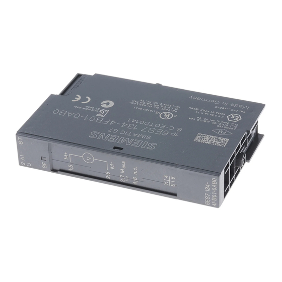
SIMATIC ET 200S distributed I/O 2AI U ST analog electronic module (6ES7134-4FB01-0AB0)
SIMATIC
ET 200S distributed I/O
2AI U ST analog electronic module
(6ES7134-4FB01-0AB0)
Manual
04/2007
A5E01076000-01
Preface
______________
Properties
______________
Parameters
______________
Diagnostics
______________
Analog value representation
______________
Connecting
1
2
3
4
5
Advertisement
Table of Contents

Related Manuals for Siemens SIMATIC 6ES7134-4FB01-0AB0


Summary of Contents for Siemens SIMATIC 6ES7134-4FB01-0AB0
- Page 1 Preface SIMATIC ET 200S distributed I/O 2AI U ST analog electronic module (6ES7134-4FB01-0AB0) ______________ Properties ______________ Parameters SIMATIC ______________ Diagnostics ET 200S distributed I/O 2AI U ST analog electronic module ______________ Analog value representation (6ES7134-4FB01-0AB0) ______________ Connecting Manual 04/2007 A5E01076000-01...
- Page 2 Trademarks All names identified by ® are registered trademarks of the Siemens AG. The remaining trademarks in this publication may be trademarks whose use by third parties for their own purposes could violate the rights of the owner.
-
Page 3: Preface
Additional support If you have any questions relating to the products described in these operating instructions, and do not find the answers in this document, please contact your local Siemens representative. http://www.siemens.com/automation/partner... - Page 4 Please contact your regional training center or the central training center in D - 90327, Nuremberg, Germany. Phone: +49 (911) 895-3200. http://www.siemens.com/sitrain Technical Support You can reach technical support for all A&D projects ● using the support request web form: http://www.siemens.com/automation/support-request...
-
Page 5: Table Of Contents
Table of contents Preface ..............................3 Properties ..............................7 2AI U ST analog electronic module (6ES7134-4FB01-0AB0) ............7 Parameters .............................. 11 Parameters...........................11 Parameter description........................12 Diagnostics .............................. 13 Diagnostics using LED display.....................13 Error types............................14 Analog value representation ........................15 Introduction ..........................15 Analog value representation for measuring range with SIMATIC S7 ..........15 Measuring ranges ........................16 Effect on analog value representation ..................18 4.4.1... - Page 6 Table of contents 2AI U ST analog electronic module (6ES7134-4FB01-0AB0) Manual, 04/2007, A5E01076000-01...
-
Page 7: Properties
Properties 2AI U ST analog electronic module (6ES7134-4FB01-0AB0) Properties ● 2 inputs for measuring voltage ● Input ranges: ± 10 V, resolution 13 bits + sign ± 5 V, resolution 13 bits + sign 1 V to 5 V, resolution 13 bits ●... - Page 8 Properties 1.1 2AI U ST analog electronic module (6ES7134-4FB01-0AB0) Usable terminal modules Usable terminal modules for 2AI U ST (6ES7134-4FB01-0AB0) TM-E15C26-A1 TM-E15C24-A1 TM-E15C24-01 TM-E15C23-01 Spring terminal (6ES7193-4CA50- (6ES7193-4CA30- (6ES7193-4CB30- (6ES7193-4CB10- 0AA0) 0AA0) 0AA0) 0AA0) TM-E15S26-A1 TM-E15S24-A1 TM-E15S24-01 TM-E15S23-01 Screw-type terminal (6ES7193-4CA40- (6ES7193-4CA20- (6ES7193-4CB20-...
- Page 9 Properties 1.1 2AI U ST analog electronic module (6ES7134-4FB01-0AB0) 2AI U ST technical specifications (6ES7134-4FB01-0AB0) Dimensions and weight Width (mm) Weight Approx. 40 g Module-specific data Supports isochronous operation Number of inputs Cable length Shielded • Max. 200 m Parameter length 4 bytes Address space 4 bytes...
- Page 10 Properties 1.1 2AI U ST analog electronic module (6ES7134-4FB01-0AB0) Suppression of interference, limits of error Interference voltage suppression for f = n x (f1 ± 1 %), (f1 = interference frequency) Common-mode interference (U • Min. 90 dB min. 70 dB Series-mode interference •...
-
Page 11: Parameters
Parameters Parameters Table 2-1 Parameters for analog input module 2 AI U ST Range of values Default setting Applicability Disable Group diagnostics (parameter • Disable Module assignment error, internal error) Enable • Disable Diagnostics: Overflow/underflow • Disable Module Enable • Disable Diagnostics: Wire break* Disable... -
Page 12: Parameter Description
Parameters 2.2 Parameter description Parameter description Smoothing The individual measured values are smoothed by digital filtering. The smoothing can be adjusted in four steps, in which the smoothing factor k multiplied with cycle time of the electronic module equals the time constant of the smoothing filter. The greater the smoothing, the greater the time constant of the filter. -
Page 13: Diagnostics
Diagnostics Diagnostics using LED display LED display ① Batch error (red) Status and error displays Event (LED) Cause Remedy No configuration or incorrect Check the parameter module plugged in. No load assignment. Check the load voltage.present There is a voltage. Evaluate the diagnostic message. -
Page 14: Error Types
Diagnostics 3.2 Error types Error types Analog input module error types Table 3-1 Error types Error type Meaning Remedy 10000: Parameter Module cannot use the Correct the configuration (align assignment error parameter for the channel: actual and set configuration). Inserted module does not Correct the parameter match the one configured. -
Page 15: Analog Value Representation
Analog value representation Introduction Electronic modules with analog outputs With the electronic module with analog inputs, continuously variable signals, such as those occurring in temperature measurement and resistance measurement, can be acquired, evaluated, and converted to digital values for further processing. Analog value representation for measuring range with SIMATIC S7 Analog value representation With the same nominal range, the digitized analog value is the same for input and output... -
Page 16: Measuring Ranges
Analog value representation 4.3 Measuring ranges Output value The following table shows the representation of the binary analog values and the corresponding decimal and hexadecimal representation of the units of the analog values. The table below shows the resolutions 11, 12, 13, and 15 bit + sign. Each analog value is entered left aligned in the ACCU. - Page 17 Analog value representation 4.3 Measuring ranges Voltage measuring ranges: 1 to 5 V Table 4-4 SIMATIC S7 format: Measuring range 1 to 5 V Measuring range Units Range 1 to 5 V Decimal Hexadecimal > 5,704 32767 7FFF Overflow 5,704 32511 7EFF Overshoot range...
-
Page 18: Effect On Analog Value Representation
Analog value representation 4.4 Effect on analog value representation Effect on analog value representation 4.4.1 Effect of the supply voltage and the operating state on analog input values The input values of the analog modules are dependent on the supply voltage for electronics/encoders and on the operating state of the PLC (CPU of the DP master). -
Page 19: Connecting
Connecting Connecting measuring sensors Introduction You can connect encoders with voltage signals to the 2AI U ST analog input module. In this chapter you will find out how to connect the measuring encoders and what to watch out for when doing so. Cables for analog signals You should use shielded and twisted-pair cables for the analog signals. - Page 20 Connecting 5.1 Connecting measuring sensors Abbreviations used The meanings of the abbreviations in the figures below are as follows: Measuring line (positive) Measuring line (negative) Analog measuring circuit reference potential Ground connection Rated load voltage 24 V DC Potential difference between inputs and reference potential of the measuring circuit M Potential difference between M and central grounding point...
- Page 21 Connecting 5.1 Connecting measuring sensors Non-isolated measuring encoders The non-isolated measuring encoders are connected to the local ground potential. You must connect M to the ground potential. Depending on local conditions or interference, potential differences U (static or dynamic) can occur between the locally distributed measuring points.
-
Page 22: Wiring Unused Channels Of The Analog Input Modules
Connecting 5.2 Wiring unused channels of the analog input modules Wiring unused channels of the analog input modules Rules Pay attention to the following instructions when wiring unused channels: ● "Deactivate" unused input channels when assigning parameters. ● A deactivated channel always returns the value 7FFF ●... -
Page 23: Index
Index 2A U ST analog electronic module Measured value resolution, 16 Technical specifications, 9 Measuring encoders, 19 2AI U ST analog electronic module Measuring ranges with SIMATIC S7, 15 Block diagram, 8 Properties, 7 Terminal assignment, 7 Non-isolated measuring encoders, 21 Analog input modules Error types, 14 Parameters... - Page 24 Index 2AI U ST analog electronic module (6ES7134-4FB01-0AB0) Manual, 04/2007, A5E01076000-01...