Table of Contents
Advertisement
Using equipment safely
Your Cable Modem Gateway product has been manufactured to meet European and local safety standards,
but you must take care if you want it to perform properly and safely.
It is important that you read this booklet completely, especially the safety instructions below.
Equipment connected to the protective earth of the building installation through the mains connection or
through other equipment with a connection to protective earth and to a cable distribution system using
coaxial cable, may in some circumstances create fire hazard. Connection to a cable distribution system has
therefore to be provided through a device providing electrical isolation below a certain frequency range
(galvanic isolator, see EN 60728-11).
If you have any doubts about the installation, operation or safety of the product, please contact your supplier.
To avoid the risk of electric shock
Disconnect the Cable Modem Gateway product from the mains supply before you connect it to (or
disconnect it from) any other equipments. Remember that contact with Mains can be lethal or causes
severe electric shock.
Never remove the product cover. Should the product fail, contact the Customer Service to arrange
repair or service.
Never allow anyone to push anything into holes, slots or any other opening in the case
Do not block the ventilation slots; never stand it on soft furnishings or carpets
Do not put anything on it which might spill or drip into it (e.g. Lighted candles or containers of liquids).
Do not expose it to dripping or splashing. If an object or liquid enters inside the Cable Modem, unplug
it immediately and contact the Customer Service.
Do not store the Cable Modem Gateway product in excessively hot, cold or damp conditions. It is
intended to operate at an ambient temperature of less than 35 degrees Celsius and a maximum humidity
level of 70%. In case of a storm, it is recommended that you unplug the product from the mains and
from the PC set or other equipment.
Leave the mains socket accessible so that you can unplug the set quickly
Telephone jacks Line 1 and Line 2 must not be connected to outside wiring.
Connecting to the mains supply
This appliance is designed to operate in the rated voltage 110 ~ 240 VAC.
If you are in any doubt about the mains lead, the plug or connection, please consult the Customer
Service.
Only the power adapter supplied with the product has to be used.
Ensuring optimum performance
Leave 7cm to 10cm around the appliance to ensure that proper ventilation gets to it.
Do not store your appliance on its side (if not allowed)
To clean the appliance, use a dry, clean soft cloth with no cleaning solvent or abrasive products. Clean
the ventilation openings regularly.
Safety Instructions
Page 1 / 85
Advertisement
Table of Contents

Related Manuals for Technicolor TC7200.20


Summary of Contents for Technicolor TC7200.20
-
Page 1: Safety Instructions
Safety Instructions Using equipment safely Your Cable Modem Gateway product has been manufactured to meet European and local safety standards, but you must take care if you want it to perform properly and safely. It is important that you read this booklet completely, especially the safety instructions below. Equipment connected to the protective earth of the building installation through the mains connection or through other equipment with a connection to protective earth and to a cable distribution system using coaxial cable, may in some circumstances create fire hazard. - Page 2 Limiting the Human Body Exposure to the Electromagnetic Fields Under normal use condition the user shall keep at least 20cm distance from the Cable Modem Gateway product. Environmental considerations This symbol means that your inoperative electronic appliance, and used battery when applicable, must be collected separately and not mixed with the household waste.
- Page 3 This equipment may by operating in Europe The CE Declaration of Conformity is available on the Website www.technicolor.com Responsible Party: Technicolor Connected Home Rennes 975, Avenue des Champs Blancs CS17616 35576 Cesson-Sévigné Cedex France Page 3 / 85...
-
Page 4: Table Of Contents
Chapter 1: Connections and Setup ..................7 Turning on the Wireless Voice Gateway ................7 Introduction ........................7 Wireless Voice Gateway Features ..................7 What’s on the CD-ROM....................9 Computer Requirements ....................9 Wireless Voice Gateway Overview..................10 Front Panel ........................10 Rear Panel ........................ - Page 5 2. WAN ........................31 3. Computers ......................32 4. DDNS ........................33 5. Time ........................34 6. FTP Diagnostics ....................... 35 7. Port-base Passthrough .................... 36 Gateway – Advanced Web Page Group ................37 1. Options ........................37 2. IP Filterng ........................ 39 3.
- Page 6 3. Storage Basic ......................68 3. Storage Advanced ....................69 3. Media Server......................70 VoIP – Basic Web Page Group ..................... 71 1. Basic LAN ........................ 71 2. Hardware Info ......................72 3. Event Log ........................ 73 4. CM State ........................74 Chapter 3: Networking ......................
-
Page 7: Chapter 1: Connections And Setup
CHAPTER 1: CONNECTIONS AND SETUP Turning on the Wireless Voice Gateway After installing the Wireless Voice Gateway and turn it on for the first time (and each time the modem is reconnected to the power), it goes through several steps before it can be used. Each of these steps is represented by a different pattern of flashing lights on the front of the modem. - Page 8 Propane™ technology supported, enabling the connection of more Internet users without additional network bandwidth. Plug and Play. Page 8 / 85...
-
Page 9: What's On The Cd-Rom
Electronic copy of this user’s guide in additional languages (PDF format) Adobe Acrobat Reader — application you can load to read PDF format, if you don’t have it loaded already Links to Technicolor web site Euro-DOCSIS and Euro-PacketCable are trademarks of Cable Television Laboratories, Inc. Computer Requirements... -
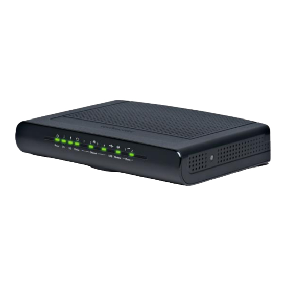
Page 10: Wireless Voice Gateway Overview
Wireless Voice Gateway Overview Front Panel Fig. 1-1 Front Panel The following illustration shows the front panel: Power - Indicates the Power status. DS - Indicates the status of Data reception by the cable modem from the Network (Downstream Traffic). US - Indicates the status of Data transmission by the cable modem to the Network (Upstream Traffic). - Page 11 The lights on the front panel LEDs are described in the table below (from left to right): ON = the LED is light, OFF = the LED is gray, FLASH = the LED is blinking. Internet TC7200.20 Power Eth. Wireless...
-
Page 12: Rear Panel
A software download and while Download FLASH FLASH updating the FLASH memory Operation Table 1-1 LED behavior Rear Panel Fig. 1-2 Rear Panel Connector Description Power Switch Power on, off the Cable modem. Power Jack Connector for DC12V. Cable Connector for the cable network. Reset To restart the modem or press over 5 seconds can default the modem. -
Page 13: Wall Mounting
Wall Mounting This article will show the user through the process of wall-mounting the Wireless Voice Gateway The Adapter has two wall-mount slots on its back panel. Two screws are needed to mount the Adapter. Fig. 1-4 Wall Mounting To do this: Ensure that the wall you use is smooth, flat, dry and sturdy and use the 2 screw holes which are 101.6 mm (4 inches) apart from each other. -
Page 14: Relationship Among The Devices
Relationship among the Devices This illustration shows a cable company that offers DOCSIS/Euro-DOCSIS and PacketCable/Euro- PacketCable compliant voice/data services. Fig. 1-5 Connection overview What the Modem Does The Wireless Voice Gateway provides high-speed Internet access as well as cost-effective, toll-quality telephone voice and fax/modem services over residential, commercial, and education subscribers on public and private networks via an existing CATV infrastructure. -
Page 15: Contact Your Local Cable Company
Contact Your Local Cable Company You will need to contact your cable company to establish an Internet account before you can use your gateway. You should have the following information ready (which you will find on the sticker on the gateway): ... -
Page 16: Attaching The Cable Tv Wire To The Wireless Voice Gateway
Attaching the Cable TV Wire to the Wireless Voice Gateway Locate the Cable TV wire. You may find it one of three ways: Connected directly to a TV, a Cable TV converter box, or VCR. The line will be connected to the jack, which should be labeled either IN, CABLE IN, CATV, CATV IN, etc. -
Page 17: Installation Procedure For Connecting To The Ethernet Interface
Installation procedure for connecting to the Ethernet interface Follow these steps for proper installation. Plug the coaxial cable to the cable wall outlet and the other end to the modem’s cable connector. Note: To ensure a fast registration of the modem, the coaxial cable must be connected to the modem before it is powered on. -
Page 18: Telephone Or Fax Connection
Telephone or Fax Connection When properly connected, most telephony devices can be used with the Wireless Voice Gateway just as with a conventional telephone service. To make a normal telephone call, pick up the handset; listen for a dial tone, then dial the desired number. -
Page 19: Chapter 2: Web Configuration
CHAPTER 2: WEB CONFIGURATION To make sure that you can access the Internet successfully, please check the following first. 1. Make sure the connection (through Ethernet) between the Wireless Voice Gateway and your computer is OK. 2. Make sure the TCP/IP protocol is set properly. 3. -
Page 20: Outline Of Web Manager
Outline of Web Manager The main screen will be shown as below. Fig. 2-2 Outline of Web Manager Main Menu: the hyperlinks on the top of the page, including Gateway, VoIP and several sub-menu items Sub Menu: under the main menu, sub menu use to enter each function, e.g., Status, Network, Firewall…... -
Page 21: Warning Message To Change The Password
Warning message to change the password At your first connection or while the password is the default one, a warning message is displayed on the top banner of each Web configuration page. We want to encourage you to change the password in order to enforce the security of your modem. -
Page 22: Gateway - Status Web Page Group
Gateway – Status Web Page Group 1. Software The information section shows the hardware and software information about your gateway. The status section of this page shows how long your gateway has operated since last time being powered up, and some key information the Cable Modem received during the initialization process with your cable company. -
Page 23: Connection
2. Connection This page reports current connection status containing startup procedures, downstream and upstream status, CM online information, and so on. The information can be useful to your cable company’s support technician if you’re having problems. Fig. 2-4 Gateway\Status\Connection Page 23 / 85... -
Page 24: Password
3. Password By default, the username is empty (“”) and the password is “admin”. This is set by different actions (non exhaustive list): at the manufactory level, following a reset factory on the modem, following a reset from the operator, following a change by the user who wants to come back to the default setting after using its own settings When the current password is the default one, the user is strongly encouraged to change the default web... - Page 25 To change the password: type the password, and re-enter it again. If the password is accepted, you are required to re log on the web pages: Fig. 2-6 Password request dialog If the password is no accepted, an error message is displayed: Please reflash the web and wait for Password dialog pop-up, then typing the correct username and password again.
-
Page 26: Diagnostics
4. Diagnostics This page offers basic diagnostic tools for you to utilize when connectivity problems occur. When you ping an Internet device, you send a packet to its TCP/IP stack, and it sends one back to yours. To use the ping Test, enter the information needed and press Start Test;... -
Page 27: Event Log
5. Event Log This page displays the contents of the SNMP event log. Press “Clear Log” button to clear the logs. Fig. 2-8 Gateway\Status\Event Log Page 27 / 85... -
Page 28: Initial Scan
6. Initial Scan To speed up the modem’s first time connection, enter known downstream frequency and/or upstream channel ID information here. Then click “Apply and Reboot” button to start scanning the cable network beginning with the values supplied here. The value is provided in Hertz. So, for 603 MHz, you must type: 603000000 Fig. -
Page 29: Backup/Restore
7. Backup/Restore Backup/Restore Settings: This page allows you to save your current settings locally on your PC, or restore settings previously saved. The default file name is “GatewaySettings.bin”. Fig 2-10 Gateway\Status\ Backup/Restore Page 29 / 85... -
Page 30: Gateway - Network Web Page Group
Gateway – Network Web Page Group 1. LAN You can activate the DHCP server function for the LAN on this page. With this activated function, your cable company’s DHCP server provides one IP address for your gateway, and your gateway’s DHCP server provides IP addresses, starting at the address you set in IP Address on the LAN page, to your PCs. -
Page 31: Wan
2. WAN You can configure the optional internal DHCP server for the WAN on this page. This can be required by some ISP providers. Select different WAN Connection Type will lead to different contents. Take the WAN connection type- DHCP for example, you can release and renew the WAN lease by pressing the buttons. You can enter a spoofed MAC address that causes your gateway networking stack to use that MAC address when communicating instead of the usual WAN MAC address, e.g., if the MAC address is 00:10:18:de:ad:03, this spoofed MAC address could be 00:11:e3:df:ad:05 or any desired MAC address. -
Page 32: Computers
3. Computers This page displays the status of the DHCP clients and current system time. You can cancel an IP address lease by selecting it in the DHCP Client Lease Info list and then clicking the Force Available button. If you do so, you may have to perform a DHCP Renew on that PC, so that it can obtain a new lease. -
Page 33: Ddns
4. DDNS - Dynamic DNS service This page allows to setup for Dynamic DNS server. Fig.2-14 Gateway\Network\DDNS DDNS Service- Choose Enabled ( www.DynDNS.org ) to enable the basic setting. Choose Disabled to close the basic setting. Username- The username that you registered with your DDNS provider. ... -
Page 34: Time
5. Time This page allows configuration and display of the system time obtained from network servers via Simple Network Time Protocol. The system has to be reset for any changes to take effect. Fig.2-15 Gateway\Network\Time Page 34 / 85... -
Page 35: Ftp Diagnostics
6. FTP Diagnostics This page allows to diagnostic download and upload transmit rate through FTP. Choose known FTP server and FileName with correct usernamne and password then choose direction to Download or Upload. Press the ‘Start’ button to start. Fig.2-16 Gateway\Network\FTP Diagnostics You will see the result on the page, when transmit done. -
Page 36: Port-Base Passthrough
7. Port-base Passthrough This page allows the configuration of each Ethernet Port. Per default, each Ethernet port is routed. If you enable the Passthrough, the Ethernet Port will have a direct connection to the Network. Note that access to this web access can be denied by your Cable operator Fig.2-17 Gateway\Network\ Port-base Passthrough Page 36 / 85... -
Page 37: Gateway - Advanced Web Page Group
Gateway – Advanced Web Page Group 1. Options This page allows you to enable/disable some features of the Wireless Voice Gateway. Fig.2-18 Gateway\Advanced\Options WAN Blocking prevents others on the WAN side from being able to ping your gateway. With WAN Blocking enabled, your gateway will not respond to pings it receives, effectively “hiding”... - Page 38 WAN side. Note that page access is limited to only those who know the gateway access password. When accessing your gateway from a remote location, your must use HTTP port 8080 and the WAN IP address of the gateway. e.g., if the WAN IP address is 157.254.5.7, you would navigate to http://157.254.5.7:8080 to reach your gateway.
-
Page 39: Ip Filterng
2. IP Filtering This page enables you to enter the IP address ranges of PCs on your LAN that you don’t want to have outbound access to the WAN. These PCs can still communicate with each other on your LAN, but packets they send to WAN addresses are blocked by the gateway. -
Page 40: Mac Filtering
3. MAC Filtering This page enables you to enter the MAC address of specific PCs on your LAN that you do not wish to have outbound access to the WAN. As with IP filtering, these PCs can still communicate with each other through the gateway, but packets they send to WAN addresses are blocked. -
Page 41: Port Filtering
4. Port Filtering This page allows you to enter ranges of destination ports (applications) that you don’t want your LAN PCs to send packets to. Any packets your LAN PCs send to these destination ports will be blocked. For example, you could block access to worldwide web browsing (http = port 80) but still allow email service (SMTP port 25 and POP-3 port 110). -
Page 42: Forwarding
5. Forwarding For LAN WAN communications, the gateway normally only allows you to originate an IP connection with a PC on the WAN; it will ignore attempts of the WAN PC to originate a connection onto your PC. This protects you from malicious attacks from outsiders. - Page 43 Press ‘Create Ipv4’ button to specify rules. Choose Service Name or Port number range to set up. IP Address 0.0.0.0 means allow all IP address. This will cause inbound packets that match to be forwarded to that PC rather than blocked. As these connections are not tracked, no entry is made for them in the Connection Table.
-
Page 44: Port Triggers
6. Port Triggers Some Internet activities, such as interactive gaming, require that a PC on the WAN side of your gateway be able to originate connections during the game with your game playing PC on the LAN side. You could use the Advanced-Forwarding web page to construct a forwarding rule during the game, and then remove it afterwards (to restore full protection to your LAN PC) to facilitate this. - Page 45 Press ‘Create’ button to specify rules. Choose Service Name or Port number range to set up. IP Address 0.0.0.0 means allow all IP address. This will cause inbound packets that match to be forwarded to that PC rather than blocked. As these connections are not tracked, no entry is made for them in the Connection Table.
-
Page 46: Dmz Host
7. DMZ Host Use this page to designate one PC on your LAN that should be left accessible to all PCs from the WAN side, for all ports. e.g., if you put an HTTP server on this machine, anyone will be able to access that HTTP server by using your gateway IP address as the destination. -
Page 47: Rip Setup
8. RIP (Routing Information Protocol) Setup This feature enables the gateway to be used in small business situations where more than one LAN (local area network) is installed. The RIP protocol provides the gateway a means to “advertise” available IP routes to these LANs to your cable operator, so packets can be routed properly in this situation. -
Page 48: Gateway - Firewall
Gateway – Firewall Web Page Group 1. Web Content Filtering These pages allow you to enable, disable, and configure a variety of firewall features associated with web browsing, which uses the HTTP protocol and transports HTML web pages. On these pages, you designate the gateway packet types you want to have forwarded or blocked. -
Page 49: Tod Filter
2. TOD Filtering Use this page to set rules that will block specific LAN side PCs from accessing the Internet, but only at specific days and times. Specify a PC by its hardware MAC address, and then use the tools to specify blocking time. -
Page 50: Local Log
3. Local Log The gateway builds a log of firewall blocking actions that the firewall has taken. Using the Local Log page lets you specify an email address to which you want the gateway to email this log. You must also tell the gateway your outgoing (i.e. -
Page 51: Remote Log
4. Remote Log The Remote Log page allows you to specify the IP address where a SysLog server is located on the LAN Side and select different types of firewall events that may occur. Then, each time such an event occurs, notification is automatically sent to this log server. -
Page 52: Gateway - Parental Control Web Page Group
Gateway – Parental Control Web Page Group 1. Basic This page allows you to enable, disable, and configure a variety of firewall features associated with web browsing, which uses the HTTP protocol and transports HTML web pages. On these pages, you designate the gateway packet types you want to have forwarded or blocked. -
Page 53: Gateway - Wireless Web Page Group
Gateway – Wireless Web Page Group The Wireless web pages group enables a variety of settings that can provide secure and reliable wireless communications for even the most demanding tech-savvy user. The Wireless Voice Gateway offers a choice of 802.11b/g/n, WPA and WPA-PSK authentication of your PCs to the gateway, 64 and 128 bit WEP encryption of communication between the gateway and your PCs to guaranty security, and an Access Control List function that enables you to restrict wireless access to only your specific PCs. -
Page 54: Radio
1. Radio To set the basic configuration for the wireless features, click RADIO from the Wireless menu. These must match the settings you make on your wireless-equipped PC on the LAN side. Fig.2-31 Gateway\Wireless\Radio Interface: The wireless radio in your gateway can be completely de-activated by changing Interface to Disabled. - Page 55 Value List or Range Default Network Name Set the Network Name (also Up to 32-character string (SSID) known as SSID) of this containing ASCII TECHNICOLOR network. characters only Network Type Select Closed to hide the network from active scans. Open, Closed Open Select Open to reveal the network to active scans.
-
Page 56: Primary Network
2. Primary Network This page allows you to configure the Network Authentication. It provides several different modes of wireless security. You will have to enter proper information according to the mode you select. Fig. 2-32 Gateway\Wireless\Primary Network Page 56 / 85... - Page 57 802.11x Authentication introduction If you enable the 802.11x authentication function, you will have to offer the following information- WPA (Wi-Fi Protected Access)/WPA2: It must be used in conjunction with an authentication server such as RADIUS to provide centralized access control and management. It can provide stronger encryption and authentication solution than none WPA modes.
- Page 58 ■ WPA/WPA2: For the WPA/WPA2 network Authentication, the settings that you can adjust including WPA/WPA2 Encryption, RADIUS Server, RADIUS Port, RADIUS Key, Group Key Rotation Interval, and WPA/WPA2 Re-auth Interval. WPA/WPA2 Encryption: There are two types that you can choose, AES, TKIP+AES. TKIP takes the original master key only as a starting point and derives its encryption keys mathematically from this mater key.
- Page 59 ■ WPA-PSK/ WPA2-PSK: For the WPA-PSK/WPA2-PSK network Authentication, the settings that you can adjust including WPA/WPA2 Encryption, WPA Pre-Shared Key, and Group key Rotation Interval. WPA Pre-Shared Key: Please type the key to be between 8 and 63 characters, or 64 hexadecimal digits. Only the devices with a matching key that you set here can join this network.
-
Page 60: Wep Encryption
■ WEP Encryption: You can choose 64-bit or 128-bit according to your needs. If you choose Disabled, the Network Keys will not be shown on this page. If selected, the data is encrypted using the key before being transmitted. e.g., If you set 128-bit in this field, then the receiving station must be set to use the128 Bit Encryption, and have the same Key value too. -
Page 61: Access Control
3. Access Control This page allows you to make access control to the AP or connected clients by offering the MAC Addresses of the clients. Fig. 2-36 Gateway\Wireless\Access Control MAC Restrict Mode: Click Disabled to welcome all of the clients on the network; select Allow to permit only the clients on the list to access the cable modem;... -
Page 62: Advanced
4. Advanced This page allows you to configure some advanced settings. The factory default values should provide good results in most cases. We don’t recommend you change these settings unless you have technical knowledge of 802.11 wireless technology. For expert users, details of all settings on this web page are provided below. Fig. - Page 63 Rate: It decides the speed of data transmission. There are several rates provided here for you to choose. Choose any one of it according to your needs by using the drop-down menu. Beacon Interval: Set the period of beacon transmissions to allow mobile stations to locate and identify a BSS.
-
Page 64: Bridging
5. Bridging The Bridging page provides a location where settings can be adjusted related to the WDS (Wireless Distribution System) feature. WDS is a system that enables the interconnection of access points wirelessly. It may also be referred to as repeater mode because it appears to bridge and accept wireless clients at the same time (unlike traditional bridging). -
Page 65: Qos (Wmm) Settings
6. 802.11e QoS (WMM) Settings Wi-Fi Multimedia (WMM) is a component of the IEEE 802.11e wireless LAN standard for quality of service (QoS). The QoS assigns priority to the selected network traffic and prevents packet collisions and delays thus improving VoIP calls and watching video over WLANs. ... -
Page 66: Gateway - Usb Web Page Group
Gateway – USB Web Page Group 1. USB Basic settings This page allows basic control of the USB devices shared over the network. Enable USB Devices connected to the USB port: Control the USB devices can be enabled, for all or approved one. -
Page 67: Approved Devices Settings
2. Approved Devices settings This page allows the configuration of the USB storage devices shared over the network. Add Available USB Devices as Approved USB Devices then apply changes. If you want to remove USB devices, propose you press “Safely Remove Device” button first. Fig.2-41 Gateway/USB/Approved Devices Page 67 / 85... -
Page 68: Storage Basic
3. Storage Basic This page shows the status of the USB folders shared over the network. Basic option defines shared files in all approved devices and specified folders or only specified folders. You can edit Shared Network Folders and observe the detail of folders. Fig.2-42 Gateway/USB/Storage Basic Page 68 / 85... -
Page 69: Storage Advanced
4. Storage Advanced This page shows the status of the folders shared over the network. Advanced option provides FTP option to share files as a FTP server. Fig.2-43 Gateway/USB/Storage Advanced Page 69 / 85... -
Page 70: Media Server
5. Media Server This page controls configuration and scanning of the cable modem's media server. Choose Scan all Files will scan your approved USB devices for sharing files. Scan Files by Type for specific file type or all of types for sharing. Choose file types form Available File Types to Selected File Types. -
Page 71: Voip - Basic Web Page Group
VoIP – Basic Web Page Group 1. Basic LAN This page displays the basic LAN status of this device, including the downstream and upstream status, device information, and interface parameters. You can select specific interface from the Interface Name drop-down menu... Fig. -
Page 72: Hardware Info
2. Hardware Info The hardware Info is displayed on this page. Fig. 2-46 VoIP\Basic\Hardware Info Page 72 / 85... -
Page 73: Event Log
3. Event Log The Docsis and PacketCable event logs are displayed on this web page. Fig. 2-47 VoIP\Basic\Event log\DOCSIS Fig. 2-48 VoIP\Basic\Event log\PacketCable Page 73 / 85... -
Page 74: Cm State
4. CM State This page shows the current state of the cable modem. Fig. 2-49 VoIP\Basic\Cm state Page 74 / 85... -
Page 75: Chapter 3: Networking
CHAPTER 3: NETWORKING Communications Data communication involves the flow of packets of data from one device to another. These devices include personal computers, Ethernet, cable modems, digital routers and switches, and highly integrated devices that combine functions, like the Wireless Cable Gateway. The gateway integrates the functionality often found in two separate devices into one. -
Page 76: Cable Modem (Cm) Section
Cable Modem (CM) Section The cable modem (or CM) section of your gateway uses DOCSIS or EURO-DOCSIS Standard cable modem technology. DOCSIS or EURO-DOCSIS specifies that TCP/IP over Ethernet style data communication be used between the WAN interface of your cable modem and your cable company. A DOCSIS or EURO-DOCSIS modem, when connected to a Cable System equipped to support such modems, performs a fully automated initialization process that requires no user intervention. -
Page 77: Cable Modem (Cm) Mode
Cable Modem (CM) Mode Fig. 3-2 Cable Modem Mode Fig. 3-3 Two IP stacks are activated in cable modem mode CM (Cable Modem) Mode provides basic home networking. In this mode, two IP stacks are active: IP Stack 1 - for use by the cable company to communicate with the cable modem section only. This stack receives its IP address from the cable company during CM initialization. -
Page 78: Residential Gateway (Rg) Mode
Note that in CM Mode, packets passing to the Internet to/from your PCs do not travel through any of the IP stacks; instead they are directly bridged between the WAN and LAN sides. Residential Gateway (RG) Mode Fig. 3-4 Residential Gateway Mode Fig. - Page 79 workplace) communicate with the Cable Modem and Networking sections, to remotely access the internal web page diagnostics and configuration. This stack is also used by your cable company to deliver packets between the Internet and the gateway’s networking section so they can be routed to/from your PCs.
-
Page 80: Chapter 4: Additional Information
CHAPTER 4: ADDITIONAL INFORMATION Frequently Asked Questions Q. What if I don’t subscribe to cable TV? A. If cable TV is available in your area, data and voice service may be made available with or without cable TV service. Contact your local cable company for complete information on cable services, including high-speed internet access. - Page 81 technology achieves higher throughput by re-packaging data, reducing the number of overhead control packets, so that more useful data can be sent during a given amount of time. * Monthly subscription fee applies. ** Additional equipment required. Contact your Cable Company and ISP for any restrictions or additional fees.
-
Page 82: General Troubleshooting
Network Interface Device located on the outside of the house. If using the second line on a two-line telephone, use a 2-line to 1-line adapter cable. For more Usage and Troubleshooting Tips use the web site links provided on the CD-ROM: www.technicolor.com Page 82 / 85... -
Page 83: Service Information
Service Information If you purchased or leased your Wireless Voice Gateway directly from your cable company, then warranty service for the Digital Cable Modem may be provided through your cable provider or its authorized representative. For information on 1) Ordering Service, 2) Obtaining Customer Support, or 3) Additional Service Information, please contact your cable company. -
Page 84: Glossary
Glossary 10/100/1000 BaseT – Unshielded, twisted pair cable with an RJ-45 connector, used with Ethernet LAN (Local Area Network). “10/100/1000” indicates speed (10/100/1000 BaseT), “Base” refers to baseband technology, and “T” means twisted pair cable. Authentication - The process of verifying the identity of an entity on a network. DHCP (Dynamic Host Control Protocol) –... - Page 85 It is more efficient in mixed environments, and it can work with 802.11a/b/g networks. TECHNICOLOR Inc. 101 W. 103rd St., INH700 Indianapolis, IN. 46290 USA Tel: +1 (317) 587-3000 - Fax: +1 (317) 587-6763 www.technicolor.com...