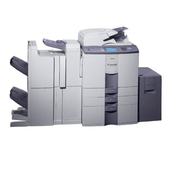
Toshiba e-STUDIO 550 Service Manual
Digital plain paper copier
Hide thumbs
Also See for e-STUDIO 550:
- Servicec support manual (84 pages) ,
- Operator's manual (36 pages) ,
- Service manual (346 pages)

Related Manuals for Toshiba e-STUDIO 550


Summary of Contents for Toshiba e-STUDIO 550
- Page 1 SERVICE MANUAL DIGITAL PLAIN PAPER COPIER e-STUDIO550/650/810 (DP-5510/6510/8110) File No.31100202 2002-06...
-
Page 2: Specifications / Accessories / Options / Supplies
TABLE OF CONTENTS SPECIFICATIONS / ACCESSORIES / OPTIONS / SUPPLIES 1. 1. Specifications 1. 2. Accessories 1. 3. Options 1. 4. Supplies 1. 5. System List OUTLINE OF THE MACHINE 2. 1. Sectional View 2. 2. Electric Parts Layout 2. 3. Symbols and Functions of Various Components 2. -
Page 3: General Operation
GENERAL OPERATION 4. 1. Overview of Operation 4. 2. Operation 4. 2. 1. Warming-up 4. 2. 2. Standby state (ready for copying) 4. 2. 3. Cassette feed copying with [START] key ON 4. 2. 4. Bypass copying 4. 2. 5. Interrupt copying 4. -
Page 4: Scanning Section
SCANNING SECTION 6. 1. Function 6. 2. Construction 6. 3. Operation 6. 3. 1. Scanner motor 6. 3. 2. Two-phase motor drive circuit (fixed-current type) 6. 4. Control for Exposure Lamp 6. 4. 1. General description 6. 4. 2. Exposure lamp 6. -
Page 5: Laser Optical Unit
LASER OPTICAL UNIT 8. 1. General Description 8. 2. Structure 8. 3. Laser Diode 8. 4. Disassembly and Replacement PAPER FEEDING SYSTEM 9. 1. General Description 9. 2. Functions 9. 3. Operation 9. 3. 1. Operation of bypass pickup roller 9. -
Page 6: Drum/Cleaner Unit
11. DRUM/CLEANER UNIT 11. 1. Construction 11. 2. Functions 11. 3. Drum Temperature Detection Circuit 11. 4. Image Quality Control 11. 4. 1. General description 11. 4. 2. Principle of sensor 11. 4. 3. Outline of control 11. 4. 4. Construction 11. -
Page 7: Fuser Unit
14. FUSER UNIT 14. 1. General Description 14. 2. Operation 14. 3. Functions 14. 4. Heater Control Circuit 14. 4. 1. Configuration 14. 4. 2. Heating principle of IH coil 14. 4. 3. IH control circuit interface 14. 4. 4. IH control circuit abnormalities 14. -
Page 8: Reversing Automatic Document Feeder (Radf)
16. REVERSING AUTOMATIC DOCUMENT FEEDER (RADF) 16. 1. General Description 16. 2. Construction 16. 3. Drive System 16. 4. Signal Block Diagram 16. 5. Operations 16. 5. 1. A4 single-sided feeding (Operational condition: A4 paper/Rreproduction ratio: 100%) 16. 5. 2. A4 double-sided feeding (Operational condition: A4 paper/Reproduction ratio: 100%) 16. -
Page 9: Power Supply Unit
17. POWER SUPPLY UNIT 17. 1. Construction 17. 2. Operation of DC Output Circuits 17. 3. Output Channel 17. 4. Fuse 17. 5. Configuration of Power Supply Unit 17. 6. Power Supply Sequence 18. PC BOARDS... -
Page 10: Service Handbook
SERVICE HANDBOOK DIGITAL PLAIN PAPER COPIER e-STUDIO550/650/810 (DP-5510/6510/8110) File No.31110201 2002-06... - Page 11 1. SPECIFICATIONS / ACCESSORIES / OPTIONS / SUPPLIES 2. ERROR CODE AND SELF- DIAGNOSIS 3. ADJUSTMENT 4. PREVENTIVE MAINTENANCE (PM) 5. TROUBLESHOOTING 6. UPDATING THE FIRMWARE 7. POWER SUPPLY UNIT 8. WIRE HARNESS CONNECTION DIAGRAMS...
- Page 12 3. 7. 1. Sheet sideways deviation caused by paper feeding ..........3-32 3. 8. Adjustment of Developer Unit ....................3-34 3. 9. Adjustment of Fuser Unit ...................... 3-35 3. 9. 1. Adjustment of fuser roller pressure ................. 3-35 e-STUDIO550/650/810 CONTENTS JUNE 2002 © TOSHIBA TEC...
- Page 13 4. 6. Jig List ........................... 4-20 4. 7. Precautions for Storing and Handling Supplies ............... 4-21 4. 7. 1. Precautions for storing TOSHIBA supplies ..............4-21 4. 7. 2. Checking and cleaning of OPC drum ................ 4-21 4. 7. 3. Checking and cleaning of drum cleaning blade and transfer belt cleaning blade ..... 4-22 4.
- Page 14 7. POWER SUPPLY UNIT ......................7-1 7. 1. Output Channel ........................7-1 7. 2. Fuse ............................7-5 8. WIRE HARNESS CONNECTION DIAGRAMS ................8-1 8. 1. AC Wire Harness ........................8-2 8. 2. DC Wire Harness ....................8-4, Appendix e-STUDIO550/650/810 CONTENTS JUNE 2002 © TOSHIBA TEC...
- Page 15 File No. 31130201...
- Page 16 CONTENTS 1. COVER-1-ASM ........1 38. MAIN-CHARGER-ASM ......38 2. COVER-2-ASM ........2 39. DRUM_DRUM-DRIVE ASM....39 3. CONTROL-PANEL-ASM ......3 40. DEV DRIVE_STAY-ASM ......40 4. LOWER-FRAME-ASM ......4 41. DEVELOPER-1-ASM....... 41 5. UPPER-FRAME-ASM......5 42. DEVELOPER-2-ASM....... 42 6. FEED-DRIVE-ASM ........6 43.
- Page 17 200. TOOLS (1) ..........200 201. TOOLS (2) ..........201 202. SUPPLIES ..........202 204. REPLACE UNIT ........204 205. PM-KIT ..........205 PARTS NUMBER INDEX...
- Page 18 1. COVER-1-ASM 2. COVER-2-ASM 3. CONTROL-PANEL-ASM 4. LOWER-FRAME-ASM 5. UPPER-FRAME-ASM 6. FEED-DRIVE-ASM 7. PAPER-FEED-ASM 8. TANDEM-LCF-1-ASM 9. TANDEM-LCF-2-ASM 10. MANUAL-FEED-DRIVE- 11. MANUAL-FEED-DRIVE- 12. MANUALTRAY-ASM 1-ASM 1-ASM 13. REVERSE-DRIVE-ASM 14. REVERSE-OPEN- 15. REVERSE-OPEN- 16. ALIGNING-ROLLER- GUIDE-1-ASM GUIDE-2-ASM 17. TRANSPORT-ROLLER- 18. TRANSPORT-BELT- 19.