Samsung PL120 Service Manual
Hide thumbs
Also See for PL120:
- User manual (127 pages) ,
- User manual (126 pages) ,
- User manual (124 pages)
Table of Contents
Advertisement
SERVICE
DIGITAL CAMERA
Refer to the service manual in the GSPN (see the rear cover) for more information.
DIGITAL CAMERA
SAMSUNG PL120/PL121
MANUAL
1. Product Specification
2. Operation Instruction
3. PL120/PL121 Exploded view and parts list
4. PL120/PL121VE Exploded view and parts list
5. Firmware update
6. Adjustment
7. Block Diagram
8. PCB Diagrams
9. Schematic Diagrams
10. Disassembly and Reassembly
Contents
Advertisement
Table of Contents

Related Manuals for Samsung PL120


Summary of Contents for Samsung PL120
-
Page 1: Digital Camera
SAMSUNG PL120/PL121 SERVICE MANUAL DIGITAL CAMERA Contents 1. Product Specification 2. Operation Instruction 3. PL120/PL121 Exploded view and parts list 4. PL120/PL121VE Exploded view and parts list 5. Firmware update 6. Adjustment 7. Block Diagram 8. PCB Diagrams 9. Schematic Diagrams 10. -
Page 2: Table Of Contents
About the software........................2 − 5 2.2.1. Using Intelli-studio ...................... 2 − 5 2.3. FAQ ............................2 − 7 PL120/PL121 Exploded view and parts list .................... 3 − 1 3.1. Body assembly ........................3 − 1 3.2. Main assembly ........................3 − 2 3.3. - Page 3 9.12. CCD FPCB..........................9 − 12 10. Disassembly and Reassembly ......................10 − 1 10.1. Disassembly of main unit ......................10 − 1 10.2. Barrel disassembly ......................... 10 − 6 10.3. Barrel assembly........................10 − 10 Copyright© 1995-2011 SAMSUNG. All rights reserved.
-
Page 4: Product Specification
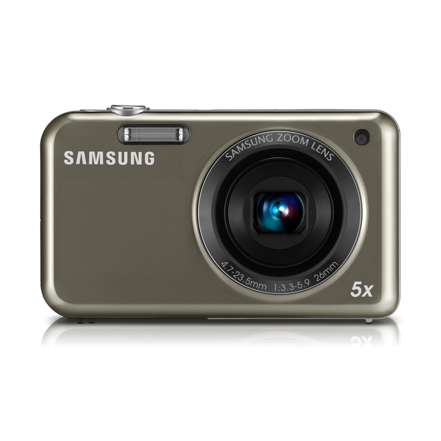
1/2.3" (Approximately 7.76 mm) CCD Effective pixels Approximately 14.2 mega-pixels Total pixels Approximately 14.4 mega-pixels Lens Samsung Lens f = 4.7 mm-23.5 mm Focal length (35 mm film equivalent: 26 mm-130 mm) F-stop range F3.3 (W)-F5.9 (T) Still image mode: 1.0X-5.0X •... - Page 5 (up to 64 GB guaranteed) DCF, EXIF 2.21, DPOF 1.1, PictBridge 1.0 • Still Image: JPEG (DCF) • File Format • Movie Clip: MJPEG (Video: MPEG-4.AVC, Audio: AAC) • Audio file: WAV Copyright© 1995-2011 SAMSUNG. All rights reserved.
- Page 6 Lithium-ion battery (BP-70A, 740 mAh: Min 700 mAh) battery Dimensions (WxHxD) 3.70 x 2.15 x 0.74in (without protrusions) Weight 5.41oz (without battery and memory card) Operating Temperature 0 ~ 40°C (32~104°F) Operating Humidity 5 ~ 85% Copyright© 1995-2011 SAMSUNG. All rights reserved.
- Page 7 1. Product Specification Software Intelli-studio Copyright© 1995-2011 SAMSUNG. All rights reserved.
-
Page 8: Instructions On How To Use The Memory Card
Table 1.1 Recorded image size Super Fine Fine Normal 30 FPS 15 FPS *Still image 1,065 1,144 1,404 1,626 1,716 1,931 Approx. 03:44 Approx. 06:21 *Movie clip Approx. 09:27 Approx. 18:16 Approx. 33:44 Approx. 1:01:24 Copyright© 1995-2011 SAMSUNG. All rights reserved. - Page 9 1. Product Specification NOTE • Available recording time may vary if you use the zoom. • Several videos were recorded in succession to determine the total recording time. Copyright© 1995-2011 SAMSUNG. All rights reserved.
-
Page 10: Lcd Monitor Indicator
Available number of photos Available recording time Memory card not inserted (Internal memory) Memory card inserted : Fully charged • • : Partially charged : Empty (Recharge) • Voice memo Auto focus frame Camera shake Zoom indicator Copyright© 1995-2011 SAMSUNG. All rights reserved. - Page 11 Auto focus option Face detection Microphone muted Table 1.4 3 Option Icons 3 Option Icons (on the left) Aperture and shutter speed Long time shutter Exposure value adjusted White balance Face tone Face retouch ISO sensitivity Copyright© 1995-2011 SAMSUNG. All rights reserved.
- Page 12 1. Product Specification 3 Option Icons (on the left) Smart filter Image adjustment (contrast, sharpness, and saturation) Burst type Digital Image Stabilization (DIS) Copyright© 1995-2011 SAMSUNG. All rights reserved.
-
Page 13: Camera Connection Diagram
1. Product Specification 1.4. Camera Connection Diagram Table 1.5 Insert a memory card with the gold-colored Removing the battery and memory card contacts facing up Table 1.6 Charging the battery AC adapter/USB cable Copyright© 1995-2011 SAMSUNG. All rights reserved. 1-10... - Page 14 Charging the battery USB cable Table 1.7 Connect your camera to your TV with the A/V cable A/V cable Table 1.8 Connect the camera to your computer(or printer) with the USB cable USB cable 1-11 Copyright© 1995-2011 SAMSUNG. All rights reserved.
-
Page 15: Identification Of Features
1. Product Specification 1.5. Identification of features Front & Top Figure 1.3 Front & Top Bottom Figure 1.4 Bottom Copyright© 1995-2011 SAMSUNG. All rights reserved. 1-12... - Page 16 1. Product Specification Back & Button Figure 1.5 Back & Button 1-13 Copyright© 1995-2011 SAMSUNG. All rights reserved.
-
Page 17: Operation Instruction
• It is not compatible with Windows XP and Vista 64-bit Edition. • Samsung is not responsible for any defects or damages caused by the use of unauthorized computer including an assembled PC. Table 2.2 For Macintosh Power Mac G3 or later Minimum 256MB RAM (Over 512MB recommended) Mac OS 10.4 or later... -
Page 18: Transferring Files With Intelli-Studio
If your camera has no new files, the pop-up window for saving new files will not appear. NOTE For Windows Vista and Windows 7, select Run iStudio.exe from the Auto Play window to start Intelli-studio. Copyright© 1995-2011 SAMSUNG. All rights reserved. -
Page 19: Transferring Files By Connecting The Camera As A Removable Disk
The computer recognizes the camera automatically. NOTE If you set the USB option to Select Mode, select Computer in the pop-up window. 6) On your computer, select My Computer→Removable →Disk→DCIM→100PHOTO . 7) Drag or save files to your computer. Copyright© 1995-2011 SAMSUNG. All rights reserved. -
Page 20: Disconnecting The Camera
1) If the status lamp on your camera is blinking, wait until it stops. 2) Click on the tool bar at the bottom right of your PC screen. 3) Click the pop-up message. 4) Click the message box indicating safely removed. 5) Remove the USB cable. Copyright© 1995-2011 SAMSUNG. All rights reserved. -
Page 21: About The Software
Change to the Sharing mode (You can send files by email or upload files to websites, such as Flickr or YouTube.) Enlarge or reduce the thumbnails in the list Select a file type View files of the selected folder on your computer Copyright© 1995-2011 SAMSUNG. All rights reserved. - Page 22 View files as thumbnails, in Smart Album, or on a map Browse folders in the connected device Browse folders in your computer Move to the previous or next folder Print files, view files on a map, store files in My Folder, or register faces Copyright© 1995-2011 SAMSUNG. All rights reserved.
-
Page 23: Faq
When the camera is connected to the USB port located on the front of the computer, the computer may not recognise the camera. Connect the camera to the USB port located on the back of the computer. Copyright© 1995-2011 SAMSUNG. All rights reserved. -
Page 24: Pl120/Pl121 Exploded View And Parts List
3. PL120/PL121 Exploded view and parts list 3. PL120/PL121 Exploded view and parts list NOTE Here are two types for PL120/PL121. PL120/PL121: Original version. 3.1. Body assembly Loc. No. Parts No. Description Available Remark 6001-002641 M1.4 x 3.5 MACHINE D2.8... -
Page 25: Main Assembly
3. PL120/PL121 Exploded view and parts list 3.2. Main assembly 2-13 2-15 2-11 2-12 2-14 2-10 Copyright© 1995-2011 SAMSUNG. All rights reserved. - Page 26 3. PL120/PL121 Exploded view and parts list Loc. No. Parts No. Description Available Remark AD92-01507A MAIN PCB ASS'Y AD07-00141A LCD ASS'Y 6003-001710 M1.4 X 3.5 TAPTITE D2.5 ZPC(BLK) AD97-20320B BARREL ASSY(BLACK) AD63-05607A CUSHION IR AD63-03625A IR CUT FILTER AD92-01402A SMD FPCB ASSY-ST90 CCD;ST90...
-
Page 27: Chamber Assembly
3. PL120/PL121 Exploded view and parts list 3.3. Chamber assembly 3-13 3-10 3-14 3-12 3-11 3-15 Loc. No. Parts No. Description Available Remark AD62-00151A CHAMBER BODY AD61-04917A FRAME MAIN AD63-05560A COVER BATTERY INNER AD63-05558A COVER BATTERY AD61-04912A PLATE BATTERY HOLDER... -
Page 28: Top Pcb Assembly
3. PL120/PL121 Exploded view and parts list 3.4. Top PCB assembly 4-10 4-11 4-13 4-12 4-14 Loc. No. Parts No. Description Available Remark AD92-01505A TO PCB SMD ASS'Y AD97-20214A ASS'Y FLASH MODULE 6003-001660 M1.4 ×3.0 TAPTITE D2.5 AD61-04910A HOLDER SPEAKER... -
Page 29: Front Cover Assembly
3. PL120/PL121 Exploded view and parts list 3.5. Front cover assembly 5-11 5-12 5-14 5-10 5-13 Loc. No. Parts No. Description Available Remark AD63-05954A COVER FRONT_BLACK BLACK AD63-05955A COVER FRONT_SILVER SILVER AD63-05956A COVER FRONT_PINK PINK AD63-05957A COVER FRONT_PURPLE PURPLE AD63-05554A... - Page 30 3. PL120/PL121 Exploded view and parts list Loc. No. Parts No. Description Available Remark AD97-20709A COVER ASSY SUB FRONT_BK BLACK AD97-20712A COVER ASSY SUB FRONT_SL SILVER 5-14 AD97-20710A COVER ASSY SUB FRONT_PK PINK AD97-20711A COVER ASSY SUB FRONT_PP PURPLE Copyright© 1995-2011 SAMSUNG. All rights reserved.
-
Page 31: Back Cover Assembly
3. PL120/PL121 Exploded view and parts list 3.6. Back cover assembly Loc. No. Parts No. Description Available Remark AD63-05555A COVER BACK AD64-03087A BUTTON-FUNCTION AD64-03088A BUTTON OK AD66-00852A LEVER ZOOM AD73-00401A RUBBER ZOOM BUTTON AD64-03089A WINDOW REAR ACCESS AD97-20213A COVER ASSY-BACK... -
Page 32: Barrel Assembly
3. PL120/PL121 Exploded view and parts list 3.7. Barrel assembly 7-18 7-48 7-44 7-17 7-43 7-16 7-42 7-47 7-15 7-41 7-39 7-50 7-40 7-14 7-28 7-38 7-13 7-34 7-37 7-45 7-12 7-35 7-11 7-36 7-10 7-46 7-51 7-33 7-29 7-32... - Page 33 3. PL120/PL121 Exploded view and parts list Loc. No. Parts No. Description Available Remark AD61-04906A PLATE-DECO BLACK AD63-04522A T/SHEET-FRONT AD63-05533A BARRIER-FRONT_PANEL BLACK AD63-05534A BARRIER-BLADE BLACK AD63-05535A BARRIER-BASE AD63-05536A BARRIER-LEVER 6107-002811 SPRING-ES (BARRIER OPEN) 6107-002810 SPRING-ES (BARRIER CLOSE) AD67-01884A LENS-G1 7-10...
- Page 34 3. PL120/PL121 Exploded view and parts list Loc. No. Parts No. Description Available Remark 7-41 AD63-03625A IR CUT FILTER 7-42 AD63-05607A CUSHION-IR FILTER 7-43 AD92-01403A ASSY PCB FPC-CCD_ST90 7-44 6003-001660 SCREW-TAPTYPE 7-45 AD97-19925A LENS ASSY-1ST 7-46 AD97-20288B BARRIER ASSY_BK BLACK...
-
Page 35: Packing Items
3. PL120/PL121 Exploded view and parts list 3.8. Packing items Loc. No. Parts No. Description Available Remark AD43-00194A BP-70A AD39-00183A 20PIN_USB_Cable_CB20U05B AD39-00146A CBF IF(20PIN_AV_CABLE_SCC-AV20) AD44-00146A AC_ADAPTOR_SAC-48_EXP AD44-00147A AC_ADAPTOR_SAC-48_CHI AD44-00143A AC_ADAPTOR_SAC-48_USA AD44-00145A AC_ADAPTOR_SAC-48_UK AD44-00148A AC_ADAPTOR_SAC-48_AUS AD44-00144A AC_ADAPTOR_SAC-48_ARG AD63-02604A STRAP_KENOX_S860_BLACK AD63-02596A STRAP_KENOX_S730_SILVER... -
Page 36: Pl120/Pl121Ve Exploded View And Parts List
4. PL120/PL121VE Exploded view and parts list 4. PL120/PL121VE Exploded view and parts list NOTE Here are two types for PL120/PL121. PL120/PL121VE: The changes of some parts from PL120/PL121. 4.1. Body assembly Loc. No. Parts No. Description Available Remark AD61-05249A... -
Page 37: Main Assembly
4. PL120/PL121VE Exploded view and parts list 4.2. Main assembly Loc. No. Parts No. Description Available Remark AD97-21123A BARREL ASSY_PL120VE AD63-03625A IR CUT FILTER AD63-05607A CUSHION IR_FILTER AD92-01686A ASSY PCB MAIN 6003-001710 M1.4 X 3.5 TAPTITE 3709-001651 SD CARD SOCKET on MAIN BOARD... -
Page 38: Chamber Assembly
4. PL120/PL121VE Exploded view and parts list 4.3. Chamber assembly 3-11 3-10 Loc. No. Parts No. Description Available Remark AD62-00174A CHAMBER BODY AD66-00893A LEVER-BATTERY LOCK 6107-001833 SPRING-TS(BATTERY-LOCK) AD61-05247A PLATE BATTERY HOLDER AD61-05388A SPRING ETC-BATTERY PUSH AD61-05136A HINGE STRAP AD63-05558A COVER BATTERY... -
Page 39: Top Cover Assembly
4. PL120/PL121VE Exploded view and parts list 4.4. Top cover assembly Top cover assembly Copyright© 1995-2011 SAMSUNG. All rights reserved. -
Page 40: Front Cover Assembly
4. PL120/PL121VE Exploded view and parts list 4.5. Front cover assembly Loc. No. Parts No. Description Available Remark AD97-21326A ASSY COVER SUB FRONT_BK BLACK AD97-21327A ASSY COVER SUB FRONT_SL SILVER AD97-21328A ASSY COVER SUB FRONT_PK PINK AD97-21329A ASSY COVER SUB FRONT_PP... -
Page 41: Back Cover Assembly
4. PL120/PL121VE Exploded view and parts list 4.6. Back cover assembly Loc. No. Parts No. Description Available Remark AD63-06150A COVER BACK AD64-03354A WINDOW REAR ACCESS AD64-03352A BUTTON FUNCTION AD66-00892A LEVER ZOOM AD61-04043A HINGE BUTTON ZOOM AD64-03353A BUTTON OK AD97-21085A ASSY COVER BACK... -
Page 42: Barrel Assembly
4. PL120/PL121VE Exploded view and parts list 4.7. Barrel assembly 7-17 7-41 7-44 7-16 7-15 7-40 7-14 7-37 7-13 7-36 7-35 7-31 7-12 7-38 7-34 7-11 7-33 7-32 7-10 7-28 7-30 7-29 7-39 7-43 7-27 7-26 7-25 7-24 7-23 7-42... - Page 43 4. PL120/PL121VE Exploded view and parts list Loc. No. Parts No. Description Available Remark AD61-04906A PLATE-DECO AD63-04522A T/SHEET-FRONT AD63-05533A BARRIER-FRONT_PANEL AD63-05534A BARRIER-BLADE AD63-05535A BARRIER-BASE AD63-05536A BARRIER-LEVER 6107-002811 SPRING-ES (BARRIER OPEN) 6107-002810 SPRING-ES (BARRIER CLOSE) AD67-01884A LENS-G1 7-10 AD67-01895A BARREL-1ST 7-11...
- Page 44 4. PL120/PL121VE Exploded view and parts list Loc. No. Parts No. Description Available Remark 7-41 AD97-20416A ASSY SUB BARREL-INNER CAM (16~17) 7-42 AD97-20292B ASSY SUB BARREL-2ND NOIS (18~24, 27) 7-43 AD97-19927A ASSY LENS-3RD(29+30) 7-44 AD97-21123A ASSY BARREL-PL120VE (7-1 ~ 43)
-
Page 45: Packing Items
4. PL120/PL121VE Exploded view and parts list 4.8. Packing items Loc. No. Parts No. Description Available Remark AD43-00194A BP-70A AD39-00183A 20PIN_USB_Cable_CB20U05B AD39-00146A CBF IF(20PIN_AV_CABLE_SCC-AV20) AD44-00146A AC_ADAPTOR_SAC-48_EXP AD44-00147A AC_ADAPTOR_SAC-48_CHI AD44-00143A AC_ADAPTOR_SAC-48_USA AD44-00145A AC_ADAPTOR_SAC-48_UK AD44-00148A AC_ADAPTOR_SAC-48_AUS AD44-00144A AC_ADAPTOR_SAC-48_ARG AD63-02604A STRAP_KENOX_S860_BLACK AD63-02596A STRAP_KENOX_S730_SILVER... -
Page 46: Firmware Update
This describes how to reset the camera to factory default setting. 1) First turn on the power of the camera. Figure 5.1 2) Press the (1) WIDE button + DOWN button and then turn the (2) POWER off. Figure 5.2 Copyright© 1995-2011 SAMSUNG. All rights reserved. - Page 47 5. Firmware update 3) Turn the power of the camera on again to check whether it has been reset. Figure 5.3 Copyright© 1995-2011 SAMSUNG. All rights reserved.
-
Page 48: Version Check
2) First turn off the power of the camera. 3) Press the (1) SHUTTER button + DOWN button, and then turn the (2) POWER on. Figure 5.4 4) Check the version of the firmware and then turn the power off. Figure 5.5 Copyright© 1995-2011 SAMSUNG. All rights reserved. -
Page 49: Full Upgrade
2) Use the AC adaptor or fully charged battery for the power. • You can proceed with the upgrade only when the battery level is full (Icon showing full up to 3rd level). 3) Turn on the power of the camera. Figure 5.6 Copyright© 1995-2011 SAMSUNG. All rights reserved. - Page 50 Figure 5.7 5) The progress of the FIRMWARE upgrade will be displayed on the LCD and the upgrade will proceed. Figure 5.8 6) When the upgrade is completed, the camera will automatically be turned off. Copyright© 1995-2011 SAMSUNG. All rights reserved.
-
Page 51: Adjustment
6.1. Basic guide for adjustment NOTE • After you replace remove this word electronic parts, you must make changes for each adjustment item in the PL120. • The following table shows the necessary adjustment item for replacing each part. 1) After replacing an electronic part, you must make adjustments for each item by referring to the following table. - Page 52 Display adjusted value and whether Display adjusted value and whether it is OK (LCD) it is OK (LCD) Set process ID (EEPROM) Auto Power Off or continue with process Power Off or stand by Figure 6.1 Copyright© 1995-2011 SAMSUNG. All rights reserved.
-
Page 53: Lens Shading
On the memory card, open and check if a CSV file was generated from the adjustment. <Restriction> If the capacity of CSV file is more than 30KB, clear all of the previous data and then, record. Copyright© 1995-2011 SAMSUNG. All rights reserved. -
Page 54: B/T Level Adj
Refer to the EEPROM WRITE information and write the adjustment result to EEPROM. e) Refer to the CARD WRITE INFORMATION to write the adjustment result to the data file. 7) When the adjustment is completed, the camera will automatically be turned off. Copyright© 1995-2011 SAMSUNG. All rights reserved. -
Page 55: Iris Adj
On the memory card, open and check if a CSV file was generated from the adjustment. <Restriction> If the capacity of CSV file is more than 30KB, clear all of the previous data and then, record Copyright© 1995-2011 SAMSUNG. All rights reserved. -
Page 56: Shutter Close Time Adj
On the memory card, open and check if a CSV file was generated from the adjustment. <Restriction> If the capacity of CSV file is more than 30KB, clear all of the previous data and then, record Copyright© 1995-2011 SAMSUNG. All rights reserved. -
Page 57: Ccd Gain Adj
Set the lower and upper specification. 6) When the adjustment is completed, the camera will automatically be turned off. <Adjustment result> On the memory card, open and check if a CSV file was generated from the adjustment. Copyright© 1995-2011 SAMSUNG. All rights reserved. -
Page 58: Flash Adj
On the memory card, open and check if a CSV file was generated from the adjustment. <Restriction> If the capacity of CSV file is more than 30KB, clear all of the previous data and then, record. Copyright© 1995-2011 SAMSUNG. All rights reserved. -
Page 59: Punt Adj
Maintain distance of less than 1cm between the end of the camera body tube to the lens surface of the Infinity Callimator. • The camera must be fixed while the adjustment is made. Infinity Callimator Camera Tripod Figure 6.7 Copyright© 1995-2011 SAMSUNG. All rights reserved. - Page 60 For the adjustment in these environments, AF may not be accurate when shooting Tele or Macro. 3) Turn on the power of the camera. 4) The adjustment will automatically start. <Adjustment result> On the memory card, open and check if a CSV file was generated from the adjustment. 6-10 Copyright© 1995-2011 SAMSUNG. All rights reserved.
-
Page 61: Burning Adj
EEPROM. (This is to classify the defective operation) • EEPROM address - Davinci_125UW : 744 burn count ) , 746( Cycle in progress ) c) When the Burning process is completed, the power will automatically be turned off. Copyright© 1995-2011 SAMSUNG. All rights reserved. 6-11... -
Page 62: Ccd Defect Adj
Refer to the CARD WRITE information to write the number of defective cells to the data file. 4) When the adjustment is completed, the camera will automatically be turned off. <Adjustment result> On the memory card, open and check if a CSV file was generated from the adjustment. 6-12 Copyright© 1995-2011 SAMSUNG. All rights reserved. -
Page 63: Backlash Adj
Prepare the log file and move to Wide. 4) When the adjustment is completed, the camera will automatically be turned off. <Adjustment result> On the memory card, open and check if a CSV file was generated from the adjustment. Copyright© 1995-2011 SAMSUNG. All rights reserved. 6-13... -
Page 64: Serial Number Writing Process
3) Turn on the power of the camera Figure 6.9 4) The change of Serial Number will be done automatically. 5) 5. When the adjustment is completed, the camera will automatically be turned off. 6-14 Copyright© 1995-2011 SAMSUNG. All rights reserved. - Page 65 6. Adjustment <Process result> When checking the version (Press SHUTTER button + DOWN button to turn on), S/N appears on the screen. Figure 6.10 Copyright© 1995-2011 SAMSUNG. All rights reserved. 6-15...
-
Page 66: Block Diagram
RAW IMAGE Block TG + AFE S P I 14M CCD (ADDI9004 HD,VD, Ima ge S e ns or XBCZRL) CCLK MOTOR DEBUG LENS Drive r IC INTERFACE 1ch. MIC (BU24033GW) pe a ke r UART Copyright© 1995-2011 SAMSUNG. All rights reserved. -
Page 67: Pcb Diagrams
R136 R106 R135 R102 C313 R103 R138 R107 C105 C102 R134 U100 C315 Q300 C405 C406 R119 C115 C206 U400 Y101 R204 C201 R203 R202 FC41 U200 U402 HOLE400 C204 R120 C208 C207 C205 Copyright© 1995-2011 SAMSUNG. All rights reserved. -
Page 68: Main Pcb(Bottom)
R121 C609 R104 R611 R610 C608 C607 MOT_S TATE2 MOT_S TATE1 C605 MOT_S DO F400 MOT_S EN S H_EN C501 NR604 MOT_S CK MOT_S DI NR603 C606 U500 MOT_CLK J 200 ZP IA R217 Copyright© 1995-2011 SAMSUNG. All rights reserved. -
Page 69: Top Pcb(Top)
8. PCB Diagrams 8.3. TOP PCB(TOP) C117 C109 C236 Copyright© 1995-2011 SAMSUNG. All rights reserved. -
Page 70: Top Pcb(Bottom)
8. PCB Diagrams 8.4. TOP PCB(BOTTOM) R122 D120 R113 C114 C107 C119 R101 C238 Q201 C240 Copyright© 1995-2011 SAMSUNG. All rights reserved. -
Page 71: Key Pcb(Top)
8. PCB Diagrams 8.5. KEY PCB(TOP) HOLE1 S W_10 S W8 S W1 S W4 S W5 S W2 HOLE2 Copyright© 1995-2011 SAMSUNG. All rights reserved. -
Page 72: Key Pcb(Bottom)
8. PCB Diagrams 8.6. KEY PCB(BOTTOM) Copyright© 1995-2011 SAMSUNG. All rights reserved. -
Page 73: Ccd Fpcb
8. PCB Diagrams 8.7. CCD FPCB Copyright© 1995-2011 SAMSUNG. All rights reserved. -
Page 74: Schematic Diagrams
AGND AGND Y101 UART_TX UART_RX EJ TDO CX3225S B12000F0GFJ 07 CFG6 EJ TDI GND2 XTAL2 CFG3 EJ TCK AGND EJ TMS XTAL1 GND1 AGND C115 0.018NF NR100 3.3K AGND AGND AGND AGND DEVELOP MENT_CON'T Copyright© 1995-2011 SAMSUNG. All rights reserved. -
Page 75: Main Pcb-2
DR2_RAS _ NC16 XRAMRAS DR2_CKE NC17 RAMCKEN R202 DR2_CLK NC18 120OHM DR2_CLK_ DR2_CS _ XRAMCS DR2_WE_ R201 22OHM XRAMWE XRAMCLK DR2_VREF DR2_ODT 1_8VCC_DDR R203 C201 10KOHM 100NF RAMVREF R204 C206 10KOHM 100NF AGND AGND Copyright© 1995-2011 SAMSUNG. All rights reserved. -
Page 76: Main Pcb-3
AGND GP O3 R323 4.7ohm S QCNT GP O4 GP O5 OFDC1 GP O6 R324 4.7ohm OFDC2 AGND AGND R325 4.7ohm Q300 R300 220Kohm S UB_CNTL S UB_CNTL1 S UB_CNTL2 R301 12KOHM AGND AGND Copyright© 1995-2011 SAMSUNG. All rights reserved. -
Page 77: Main Pcb-4
D400 C424 4700NF INV7 P WR_ENB AGND 5VCC BLEDP R412 RB501V_40 U402 U404 HOLE400 HOLE401 S MR-TS -4-3-3 S MDGAS KET C403 C419 BL_DIM TES T_TP 4700NF AGND AGND AGND AGND BLEDN AGND AGND Copyright© 1995-2011 SAMSUNG. All rights reserved. -
Page 78: Main Pcb-5
R500 R501 OUT6A S H_P R502 OUT6B OUT4A S H_N ND_P OUT4B ND_N AGND AGND AGND AGND AGND AGND S H_EN MOT_CLK MOT_S EN MOT_S CK MOT_S DI MOT_S DO MOT_S TATE1 MOT_S TATE2 Copyright© 1995-2011 SAMSUNG. All rights reserved. -
Page 79: Main Pcb-6
6.3V C603 C610 10000nF/10% 1000nF/10% 470NF R602 2.2K 6.3V AGND C611 AGND AGND 470NF AGND C600 100NF MIC_P MICP L601 4.7UH C601 S P KR_N S P KRN 100NF MIC_N MICN R603 2.2K AGND Copyright© 1995-2011 SAMSUNG. All rights reserved. -
Page 80: Main Pcb-7
2200NF CP 3 C701 4.7uF C708 4700NF CP 4 C709 2200NF CP 4 C710 4.7uF BLEDP BLEDN C702 4700NF C711 4700NF KDR720E D700 C703 4700NF LCD_ID2 VCOM E700 ICVN0518X400FR AGND AGNDAGND AGND MAIN_LCD CON. Copyright© 1995-2011 SAMSUNG. All rights reserved. -
Page 81: Main Pcb-8
S FM_MIS O GND_0 R803 4.7K FP GA_ENB R805 WP _ACC S CLK S FM_S CLK C817 10KOHM S I_S IO0 S FM_MOS I C806 1000nF/10% 4700NF AGND S ERIAL FLAS H AGND AGND AGND Copyright© 1995-2011 SAMSUNG. All rights reserved. -
Page 82: Top Pcb-1
22OHM AGND AGND AGND C117 C109 C114 0.33NF 0.47NF AGND AGND AGND AGND R112 200ohm R115 10KOHM GND1 GND2 GND3 TP 101 TP 103 TP 102 AGND TP _1 TP _1 TP _1 AGND Copyright© 1995-2011 SAMSUNG. All rights reserved. -
Page 83: Top Pcb-2
D121 33NF 33NF 15nF/16V 15nF/16V S TR_READY S TR_CHARGE C254 C256 S W205 1000nF/10% 1000nF/10% S KRWAEE030 S TR_TRIG AGND AGND AGND AGND AGND AGND AGND S W206 D122 AGND AGND AGND AGND Copyright© 1995-2011 SAMSUNG. All rights reserved. 9-10... -
Page 84: Key Pcb
S W7 DOME_P AD_S W 33KOHM S W5 DOME_P AD_S W KEY_TELE AGND AGND AGND 3_3VCC_MAIN LED1 3_3VCC_KA S W9 HOLE1 HOLE2 DOME_P AD_S W P LAY_KEY P LAY 150OHM 1000nF/10% AGND FUNC_LED AGND 9-11 Copyright© 1995-2011 SAMSUNG. All rights reserved. -
Page 85: Ccd Fpcb
V8S 1 VGND V8S 2 V8S 2 ICX631S QW S UB S UB VOUT 13VCC_S ENS OR N6_5VCC_S ENS OR VOG2 VOG2 VOG1 VOG1 AGND AGND1 VHLD VHLD S UB_CONT AGND AGND AGND Copyright© 1995-2011 SAMSUNG. All rights reserved. 9-12... -
Page 86: Disassembly And Reassembly
Always use the anti-static mat and wrist band, as the parts can be damaged from static PCB Type electricity from the hand. CONTACT Type Be careful of damage of deformation of parts from the pin set. Disassembly image Disassembly description Remove 2 Screws. Remove 1 Screw. 10-1 Copyright© 1995-2011 SAMSUNG. All rights reserved. - Page 87 10. Disassembly and Reassembly Disassembly image Disassembly description Remove 2 Screws. Remove the Back Cover Assy. Remove the Side Cover. Remove the 1 Connector. Remove the Front Cover Assy. Copyright© 1995-2011 SAMSUNG. All rights reserved. 10-2...
- Page 88 10. Disassembly and Reassembly Disassembly image Disassembly description Remove 2 Screws. Remove the 1 Connector. Remove the Key PCB Assy. Remove the 1 Connector. Remove the LCD. 10-3 Copyright© 1995-2011 SAMSUNG. All rights reserved.
- Page 89 10. Disassembly and Reassembly Disassembly image Disassembly description Remove the 2 Locks and 2 Connectors. Remove the Barrel Assy. Remove 3 Screws. Remove the CCD PCB Assy. Remove 2 Screws. Copyright© 1995-2011 SAMSUNG. All rights reserved. 10-4...
- Page 90 10. Disassembly and Reassembly Disassembly image Disassembly description Remove the 1 Lock and 1 Connector. Remove the Top PCB Assy. Remove 2 Screws. Remove the Main PCB Assy. 10-5 Copyright© 1995-2011 SAMSUNG. All rights reserved.
-
Page 91: Barrel Disassembly
10.2. Barrel disassembly Disassembly image Disassembly description Remove the soldering from Shutter FPCB. Remove the 1 Screw. Remove the 2 Screws. Remove the 3 Screws and 1 Lock. Remove the Lens Base Assy. Copyright© 1995-2011 SAMSUNG. All rights reserved. 10-6... - Page 92 CAUTION Be careful about the spring. This is the Separate state of the spring and 3rd sub barrel assy. Remove the Shutter FPCB Holder. 10-7 Copyright© 1995-2011 SAMSUNG. All rights reserved.
- Page 93 10. Disassembly and Reassembly Disassembly image Disassembly description Remove the Outer Guide Barrel. Remove the Outer Guide Barrel. Remove the Outer Cam Barrel. Remove the Outer Cam Barrel. Remove the Outer Guide Plate Barrel. Copyright© 1995-2011 SAMSUNG. All rights reserved. 10-8...
- Page 94 10. Disassembly and Reassembly Disassembly image Disassembly description Remove the Cam SUB Barrel Assy. Remove the Cam SUB Barrel Assy. Remove the 2nd SUB Barrel Assy. Remove the 2nd SUB Barrel Assy. Remove the Guide Plate. 10-9 Copyright© 1995-2011 SAMSUNG. All rights reserved.
-
Page 95: Barrel Assembly
Be careful about the location of (c), (d). This is the assembled state of the 2nd sub barrel assembly. To assemble match the Point (a)&(b). CAUTION Be careful about the location of (c), (d). Copyright© 1995-2011 SAMSUNG. All rights reserved. 10-10... - Page 96 This is the assembled state of the outer guide plate barrel. To assemble match the Point (a)&(b). CAUTION Be careful about the location of (c),(d). This is the assembled state of the Outer cam barrel. 10-11 Copyright© 1995-2011 SAMSUNG. All rights reserved.
- Page 97 This is the assembled state of the Outer guide barrel. Assemble the FPCB Holder from Shutter FPCB. This is the assembled state of the FPCB Holder. Assemble the Spring and 3rd Barrel assembly from Lens Base assembly. Copyright© 1995-2011 SAMSUNG. All rights reserved. 10-12...
-
Page 98: Copyright© 1995-2011 Samsung. All Rights Reserved
Assemble the AF motor assembly from Lens Base assembly. Assemble the 1 Screw from AF motor assembly. To assemble match the Point (a)&(b) as shown in the figure. Assemble the 1 Screw from Lens Base assembly. Assemble the FPCB. 10-13 Copyright© 1995-2011 SAMSUNG. All rights reserved. - Page 99 Shutter FPCB. Assemble the Screw and as shown in the Point (a) and (b) from FPCB Assemble the 2 Screws from zoom motor assy. This is the assembled state of the barrel assembly. Copyright© 1995-2011 SAMSUNG. All rights reserved. 10-14...
- Page 100 CIS, Africa E.Asia, W.Asia, https://gspn2.samsungcsportal.com China, Japan N.America, S.America https://gspn3.samsungcsportal.com This Service Manual is a property of Samsung Electronics © 2011 Samsung Electronics Co.,Ltd. Co.,Ltd. All rights reserved. Any unauthorized use of Manual can be punished under Printed in Korea applicable International and/or domestic law.