Panasonic EY4550 Service Manual
Hide thumbs
Also See for EY4550:
- Operating instructions manual (17 pages) ,
- Operating instructions manual (145 pages)
Advertisement
Quick Links
TABLE OF CONTENTS
1 Warning -------------------------------------------------------------- 2
2 Specifications ----------------------------------------------------- 2
3 Troubleshooting Guide ----------------------------------------- 3
4 Disassembly and Assembly Instructions ---------------- 5
5 Wiring Connection Diagram ---------------------------------- 9
6 Schematic Diagram ---------------------------------------------- 9
7 Exploded View and Replacement Parts List -----------10
Model No.
Europe
PAGE
© Panasonic Electric Works Co., Ltd. 2011.
All rights reserved. Unauthorized copying and distri-
bution is a violation of law.
Order Number PTD1105E39CE
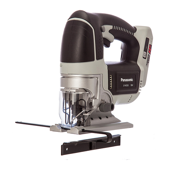
Cordless Jigsaw
EY4550
PAGE
Advertisement

Related Manuals for Panasonic EY4550


Summary of Contents for Panasonic EY4550
-
Page 1: Table Of Contents
4 Disassembly and Assembly Instructions ---------------- 5 5 Wiring Connection Diagram ---------------------------------- 9 6 Schematic Diagram ---------------------------------------------- 9 7 Exploded View and Replacement Parts List -----------10 © Panasonic Electric Works Co., Ltd. 2011. All rights reserved. Unauthorized copying and distri- bution is a violation of law. -
Page 2: Warning
1 Warning Caution: • Pb free solder has a higher melting point that standard solder; Typically the melting point is 50 - 70°F (30 - 40°C) higher. Please use a soldering iron with temperature control and adjust it to 750 ± 20°F (400 ± 10°C). In case of using high temperature solder- ing iron, please be careful not to heat too long. -
Page 3: Troubleshooting Guide
3 Troubleshooting Guide (Refer to Wiring Connection Diagram) - Page 4 3.1. Trial Operation (after checking Troubleshooting Guide.) 3.1.1. ASSEMBLY • Confirm if there is NO gap between Housing A and B by pinching the lead wires. • Confirm if there is NO deformation on the battery terminals. • Confirm all screws are tightened firmly. 3.1.2.
-
Page 5: Disassembly And Assembly Instructions
4 Disassembly and Assembly Instructions 4.1. How to Disassemble the Blade. Ref. No. 1A Procedure 1A Removal of blade. WARNING: To reduce the risk of injury, always remove battery pack before removing/installing the blade. 1. Unhook and pull out the dust cover. 2. - Page 6 Procedure 1A → 1B → 1C Ref. No. 1C Removal of the housing. 1. Loosen 1 housing screw (2.9X16). 2. Loosen 9 housing screw (4X16). 3. Hold the housing A and take the housing B up vertically. Procedure 1A → 1B → 1C → 1D Ref.
- Page 7 Procedure 1A → 1B → 1C → 1D → 1E Ref. No. 1E Removal of the switch. 1. Pull out the lead wires from the pressure terminal. (for reassembly) 1. Connect the motor lead wires (black and red) with the heat contraction tube.
- Page 8 Procedure 1A → 1B → 1C → 1D → 1E → 1F Ref. No. 1G Assembly of main unit. → 1G 1. Press fit the lead wire firmly. 2. Insert the LED into the hole of gear box block until all the way back. NOTE: Make sure the lead wires are not pulled back when placing them in the housing rib.
-
Page 9: Wiring Connection Diagram
5 Wiring Connection Diagram 6 Schematic Diagram... -
Page 10: Exploded View And Replacement Parts List
7 Exploded View and Replacement Parts List Model No. : EY4550 Exploded View... - Page 11 Model No. : EY4550 Parts List Ref. Safety Part No. Part Name & Description Q'ty Remarks WEY4550K3078 HOUSING AB SET WEY4550K9068 TAPPING SCREW 1 (2.9X16) WEY4550K9138 TAPPING SCREW 9 (4X16), (9PCS/PK) WEY4550L2338 LED ASSEMBLY WEY4550H3248 SWITCH LOCK LEVER WEY4550L0178 SPRING...