Table of Contents
Advertisement
Quick Links
SCALANCE X-300
SIMATIC NET
Industrial Ethernet Switches
SCALANCE X-300
Operating Instructions
05/2016
A5E01113043-20
___________________
Preface
___________________
Safety instructions
___________________
Introduction
___________________
Network topologies
___________________
Description of the device
___________________
Installation
___________________
Connecting
___________________
Configuration, displays and
display elements
___________________
Technical specifications
___________________
Approvals, certificates,
standards
___________________
Accessories
___________________
Graphics
___________________
Appendix
1
2
3
4
5
6
7
8
9
10
11
A
Advertisement
Table of Contents

Related Manuals for Siemens SCALANCE X320-3LD FE


Summary of Contents for Siemens SCALANCE X320-3LD FE
- Page 1 ___________________ SCALANCE X-300 Preface ___________________ Safety instructions ___________________ SIMATIC NET Introduction ___________________ Network topologies Industrial Ethernet Switches SCALANCE X-300 ___________________ Description of the device ___________________ Installation Operating Instructions ___________________ Connecting ___________________ Configuration, displays and display elements ___________________ Technical specifications ___________________ Approvals, certificates, standards ___________________...
-
Page 2: Legal Information
Note the following: WARNING Siemens products may only be used for the applications described in the catalog and in the relevant technical documentation. If products and components from other manufacturers are used, these must be recommended or approved by Siemens. Proper transport, storage, installation, assembly, commissioning, operation and maintenance are required to ensure that the products operate safely and without any problems. -
Page 3: Preface
Preface Purpose of the Operating Instructions These Operating Instructions describe the design and functions of the compact and modular Industrial Ethernet Switches of the SCALANCE X-300 product line and support you during installation, commissioning, and troubleshooting on site. Validity of the Operating Instructions These Operating Instructions are valid for the following product groups of the SCALANCE X- 300 product line, see also section Product overview (Page 27). - Page 4 Preface Overview of the technical documentation of the IE Switches X-300 The technical documentation of the X-300 product line is divided into hardware and software and can be found in the following documents: ● PH - Configuration Manual (PDF) The software is described in the configuration manual (PH) for both product lines X-300 and X-400.
- Page 5 – On paper under order numbers: - English version: 6GK1 970-1BA10-0AA1 - German version: 6GK1 970-1BA10-0AA0 – In German and English on the Internet on the pages of Siemens Automation Customer Support under the following entry ID: 27069465 (http://support.automation.siemens.com/WW/view/en/27069465) If you have questions on the use of SIMATIC NET products, please contact your Siemens sales partner.
- Page 6 Siemens recommends strongly that you regularly check for product updates. For the secure operation of Siemens products and solutions, it is necessary to take suitable preventive action (e.g. cell protection concept) and integrate each component into a holistic, state-of-the-art industrial security concept.
-
Page 7: Table Of Contents
Table of contents Preface ..............................3 Safety instructions ..........................15 Important notes on using the device ..................15 PELV ............................17 Important notes on using the device in hazardous areas ............18 Security recommendations ..................... 19 Introduction ............................25 Basics of Ethernet switching ....................25 Product overview ........................ - Page 8 Table of contents 4.2.1.10 SCALANCE X310FE product characteristics ................ 58 4.2.1.11 SCALANCE X320-1FE product characteristics ..............59 4.2.1.12 SCALANCE X320-3LD FE product characteristics ..............60 4.2.2 Product group X-300M ......................61 4.2.3 Product group XR-300M ......................63 4.2.4 X-300EEC product group ....................... 65 4.2.4.1...
- Page 9 Table of contents 4.3.2.1 1000Base-SX .......................... 93 4.3.2.2 1000Base-LX / 100Base-FX ....................94 4.3.3 Signaling contact ........................95 C-PLUG (configuration plug) ....................95 Components of the product ....................99 4.5.1 Components of the product ....................99 4.5.2 X-300M components of the product ..................99 4.5.3 Components of the XR-300M product ..................
- Page 10 Table of contents 6.5.2.2 100 to 240 VAC - product group X-300EEC ................ 139 6.5.2.3 100 to 240 VAC - XR-300M EEC product group ..............140 6.5.2.4 100 to 240 VAC XR-300M PoE product group ..............140 6.5.2.5 Fitting the connector for 100 to 240 V AC ................140 6.5.2.6 Connecting the 100 to 240 VAC power supply ..............
- Page 11 Table of contents X-300M PoE technical specifications ..................191 8.7.1 Construction, installation and environmental conditions ............191 8.7.2 Connectors and electrical data ..................... 193 8.7.3 Cable lengths ........................195 8.7.4 Other properties ........................196 XR-300M PoE technical specifications ................. 197 8.8.1 Construction, installation and environmental conditions ............
- Page 12 Table of contents XR-300M EEC product group ....................249 9.5.1 XR-300M EEC approvals, certificates ................. 249 9.5.2 SCALANCE X-300 declaration of conformity ............... 253 9.5.3 Overview of XR-300M EEC approvals ................. 254 9.5.4 XR-300M EEC mechanical stability (in operation) ............... 254 Product group X-300M PoE ....................
- Page 13 Table of contents Fitting the IE FC RJ-45 Plug ....................314 Electrical tests (EEC devices) ....................316 EMC-compatible installation of electrical Industrial Ethernet or PROFIBUS cabling ... 317 Equipotential bonding ......................318 Index..............................321 SCALANCE X-300 Operating Instructions, 05/2016, A5E01113043-20...
- Page 14 Table of contents SCALANCE X-300 Operating Instructions, 05/2016, A5E01113043-20...
-
Page 15: Safety Instructions
Safety instructions Important notes on using the device Safety notices on the use of the device The following safety notices must be adhered to when setting up and operating the device and during all associated work such as installation, connecting up, replacing or opening the device. - Page 16 Safety instructions 1.1 Important notes on using the device WARNING Safety notice for connectors with LAN (Local Area Network) marking A LAN or LAN segment, with all its associated interconnected equipment, shall be entirely contained within a single low-voltage power distribution and within a single building. The LAN is considered to be in an "environment A"...
-
Page 17: Pelv
Safety instructions 1.2 PELV Safety notices on use in hazardous areas according to ATEX and IECEx WARNING Requirements for the cabinet/enclosure To comply with EC Directive 94/9 (ATEX95) or the conditions of IECEx, this enclosure must meet the requirements of at least IP54 in compliance with EN 60529. The fiber-optic bus connections labeled SCALANCE MM900 (see type plate) may also be led through a hazardous area zone1 (see also Auto-Hotspot, section "Explosion Protection Directive (ATEX)"). -
Page 18: Important Notes On Using The Device In Hazardous Areas
Safety instructions 1.3 Important notes on using the device in hazardous areas Important notes on using the device in hazardous areas WARNING WARNING - EXPLOSION HAZARD - DO NOT DISCONNECT WHILE CIRCUIT IS LIVE UNLESS AREA IS KNOWN TO BE NON-HAZARDOUS. -
Page 19: Security Recommendations
Safety instructions 1.4 Security recommendations Safety requirements for installation According to the IEC 61131-2 standard and therefore in accordance with the EU directive 2006/95/EC (Low Voltage Directive), the devices are "open equipment" and in accordance with UL/CSA certification, they are an "open type". To fulfill requirements for safe operation with regard to mechanical stability, flame retardation, stability, and shock-hazard protection, the following alternative types of installation are specified:... -
Page 20: Operating Instructions, 05/2016, A5E01113043
● Keep the software up to date. Check regularly for security updates of the product. You will find information on this on the Internet pages "Industrial Security" ● Inform yourself regularly about security advisories and bulletins published by Siemens productCERT. - Page 21 Safety instructions 1.4 Security recommendations ● Handle user-defined private keys with great caution if you use user-defined SSH or SSL keys. ● Verify certificates and fingerprints on the server and client to avoid "man in the middle" attacks. ● We recommend that you use certificates with a key length of 2048 bits. ●...
- Page 22 Safety instructions 1.4 Security recommendations ● Use secure protocols when access to the device is not prevented by physical protection measures. ● To prevent unauthorized access to the device or network, take suitable protective measures against non-secure protocols. ● If you require non-secure protocols and services, operate the device only within a protected network area.
- Page 23 Safety instructions 1.4 Security recommendations Protocol Port number Port status Default status of Authentication the port TCP/22 Open Open HTTP TCP/80 Open Open (when configured) HTTPS TCP/443 Open Open SNTP UDP/123 Open Closed NTP (secure) (when configured) SNMP UDP/161 Open Open (when configured) PROFINET IO...
- Page 24 Safety instructions 1.4 Security recommendations SCALANCE X-300 Operating Instructions, 05/2016, A5E01113043-20...
-
Page 25: Introduction
Introduction Basics of Ethernet switching Ethernet switching Ethernet switches forward data packets directly from the input port to the appropriate output port during data exchange based on the address information. Ethernet switches operate on a direct delivery basis. Essentially, switches have the following functions: ●... - Page 26 Introduction 2.1 Basics of Ethernet switching Technical options (network topologies) The IE Switches X-300 simplify the expansion of a network regardless of the network topology. You can use an IE Switch X-300 in the following network topologies: ● Linear structure ●...
-
Page 27: Product Overview
Introduction 2.2 Product overview Product overview 2.2.1 Type designations Structure of the type designation The type designation of an IE Switch X-300 is made up of several parts that have the following meaning: Interfaces of devices without optical ports: Interface Property Electrical RJ-45 port for 10/100 Mbps. -
Page 28: Designs Of The Ie Switch X-300 Devices
Note SCALANCE X320-3LD FE The SCALANCE X320-3LD FE deviates from the type designation in that it has an SC port for multimode fiber-optic cable up to a maximum of 5 km in length and two SC ports for single mode fiber-optic cable up to a maximum of 26 km in length. -
Page 29: X-300 Product Group
Introduction 2.2 Product overview Image 2-1 Designs of the X-300 IE switches, example of plugging media modules into the media module slots of the XR324-12M 2.2.3 X-300 product group Device Properties Order number X304-2FE 4 x 10/100 Mbps RJ-45 ports electrical 6GK5 304-2BD00-2AA3 2 x 1000 Mbps, SC ports optical, for glass FO cable (multimode), up to max. -
Page 30: Product Group X-300M
Introduction 2.2 Product overview Device Properties Order number X308-2LD 1 x 10/100/1000 Mbps, RJ-45 ports electrical 6GK5 308-2FM00-2AA3 7 x 10/100 Mbps RJ-45 ports electrical 6GK5 308-2FM10-2AA3 2 x 1000 Mbps, SC ports optical, for glass FO cable (single mode), up to max. -
Page 31: Product Group Xr-300M
Introduction 2.2 Product overview 2.2.5 Product group XR-300M Device Properties Order number XR324-12M 2 x 24 VDC 6GK5 324-0GG00-1AR2 LEDs, connector power supply and data cable outlet on front Diagnostics port at rear XR324-12M 1 x 100 to 240 VAC 6GK5 324-0GG00-3AR2 LEDs, connector power supply and data cable outlet on front... -
Page 32: Xr-300M Eec Product Group
Introduction 2.2 Product overview Product / ports Properties Order number 1 x power supply unit 100 to 240 VAC / 60 to 250 VDC 6GK5307-2FD00-3EA3 1 x power supply unit 100 to 240 VAC / 60 to 250 VDC 6GK5307-2FD00-3GA3 Printed board varnished 2 x power supply unit 100 to 240 VAC / 60 to 250 VDC 6GK5307-2FD00-4EA3... -
Page 33: Product Group X-300M Poe
Introduction 2.2 Product overview 2.2.8 Product group X-300M PoE Device: Properties Order number X308-2M PoE 4 x 10/100/1000 Mbps, RJ-45 ports elec- 6GK5 308-2QG00-2AA2 trical 2 x 100/1000 Mbps for 2-port media mod- ules Note For more information on Power over Ethernet (PoE), refer to the Configuration Manual X- 300/X-400. -
Page 34: Sfp Transceiver
Introduction 2.2 Product overview 2.2.10 SFP transceiver SFP transceiver Type Properties Article number SFP991-1 * 1 x 100 Mbps, LC port optical for glass FO cable 6GK5 991-1AD00-8AA0 (multimode), up to max. 5 km SFP991-1 (C) * 1 x 100 Mbps, SC port optical, for glass FO 6GK5 991-1AD00-8FA0 cable (multimode), up to max. -
Page 35: Mm900 Media Modules
Introduction 2.2 Product overview Type Properties Article number Labeling on the device MM992-2SFP 2 x 100 / 1000 Mbps, SFP media module 6GK5 992-2AS00- 9922AS 8AA0 MM992-4SFP 4 x 100 / 1000 Mbps, SFP media module 6GK5 992-4AS00- 9924AS 8AA0 2.2.11 MM900 media modules Note... - Page 36 Introduction 2.2 Product overview Media module Properties Order number Labeling on the device MM992-2SFP 2 x 100/1000 Mbps, SFP media module 6GK5 992-2AS00-8AA0 9922AS MM992-2SFP (C) 2 x 100/1000 Mbps, SFP media module, varnished 6GK5 992-2AS00-8FA0 9922AS MM991-2 2 x 100 Mbps, BFOC port optical, for glass FO cable (multimode), up to 6GK5 991-2AB00-8AA0 max.
- Page 37 Introduction 2.2 Product overview Type key for the MM900 media modules The type designation of an MM900 media module is made up of several parts that have the following meaning: Interface Property BFOC port 100 Mbps multimode FO cable BFOC port 100 Mbps single mode FO cable (SC) SC port 100 Mbps multimode FO cable (up to max.
- Page 38 Introduction 2.2 Product overview SCALANCE X-300 Operating Instructions, 05/2016, A5E01113043-20...
-
Page 39: Network Topologies
Network topologies Linear structure Functional description Linear structures can be created with the IE Switches X-300. The cascading depth and total span of a network are limited only by the signal propagation times of the communication connections. Properties of the linear structure Each IE Switch X-300 communicates over a TP or FO cable with a neighboring Ethernet switch. -
Page 40: Ring With Redundancy Manager
Network topologies 3.3 Ring with redundancy manager Properties of a star structure Each IE Switch X-300 communicates over a TP or FO cable with a central switch with which all other switches are also connected within a star structure. Communication is possible over the optical or the electrical ports. - Page 41 Network topologies 3.3 Ring with redundancy manager The redundancy manager function is enabled by the SELECT/SET button or by a setting in the software. For more detailed information, refer to the configuration manual "SCALANCE X-300 and SCALANCE X-400 Industrial Ethernet Switches". In contrast to the ring ports of the redundancy clients, the ring ports of the redundancy manager are disconnected when the network is operating problem-free.
- Page 42 Network topologies 3.3 Ring with redundancy manager Device Factory setting for the ring ports Electrical Optical XR324-12M TS Port 1.1 and port 1.2 XR324-4M EEC Port 1 and port 2 XR324-4M PoE Port 1 and port 2 XR324-4M PoE TS Port 1 and port 2 Configuration example Sample configurations with IE Switch X-300, SIMATIC S7-200/300/400, operator control and...
- Page 43 Network topologies 3.3 Ring with redundancy manager Image 3-4 Ring with FO cable and redundancy manager SCALANCE X-300 Operating Instructions, 05/2016, A5E01113043-20...
-
Page 44: Redundant Coupling Of Network Segments
Network topologies 3.4 Redundant coupling of network segments Redundant coupling of network segments Redundant coupling of network segments The example of redundant coupling of two network segments as shown here, for example rings with a redundancy manager, can be implemented homogeneously with all SCALANCE X300 variants. - Page 45 Network topologies 3.4 Redundant coupling of network segments synchronize their operating statuses (one device is master and the other slave). If there are no problems, only the link from the master to the other network segment is active. If this link fails (for example due to a link-down or a device failure), the slave activates its link as long as the problem persists.
- Page 46 Network topologies 3.4 Redundant coupling of network segments SCALANCE X-300 Operating Instructions, 05/2016, A5E01113043-20...
-
Page 47: Description Of The Device
Description of the device Compatibility of SCALANCE X-300 Compatibility list Note Modular devices (M) The MM900 media modules and the SFP transceivers are used only in modular devices (M). The following products and devices are compatible with IE Switches X-300: ●... - Page 48 Description of the device 4.2 Product groups ● Network components in a ring structure with IE Switch X-300 as redundancy manager – Electrical ring structure: ESM/OSM SCALANCE X-200 SCALANCE X-200IRT SCALANCE XF200 SCALANCE XF204IRT SCALANCE X-300 (it may be necessary to configure other ring ports) SCALANCE X-400 –...
-
Page 49: Product Groups
Description of the device 4.2 Product groups Product groups 4.2.1 X-300 product group 4.2.1.1 SCALANCE X304-2FE product characteristics Possible attachments The SCALANCE X304-2FE provides the following options for the connection of end devices or other network segments: ● 4 RJ-45 jacks ●... -
Page 50: Scalance X306-1Ld Fe Product Characteristics
Description of the device 4.2 Product groups 4.2.1.2 SCALANCE X306-1LD FE product characteristics Possible attachments The SCALANCE X306-1LD FE provides the following options for the connection of end devices or other network segments: ● 6 RJ-45 jacks ● 1 FO port (for single mode fiber) Image 4-2 SCALANCE X306-1LD FE Column... -
Page 51: Scalance X307-3 Product Characteristics
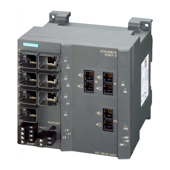
Description of the device 4.2 Product groups 4.2.1.3 SCALANCE X307-3 product characteristics Possible attachments The SCALANCE X307-3 provides the following options for the connection of end devices or other network segments: ● 7 RJ-45 jacks ● 3 FO ports (for multimode fiber) Image 4-3 SCALANCE X307-3 Column... -
Page 52: Scalance X307-3Ld Product Characteristics
Description of the device 4.2 Product groups 4.2.1.4 SCALANCE X307-3LD product characteristics Possible attachments The SCALANCE X306-3LD provides the following options for the connection of end devices or other network segments: ● 7 RJ-45 jacks ● 3 FO ports (for single mode fiber) Image 4-4 SCALANCE X307-3LD Column... -
Page 53: Scalance X308-2Lh Product Characteristics
Description of the device 4.2 Product groups 4.2.1.5 SCALANCE X308-2LH product characteristics Possible attachments The SCALANCE X308-2LH provides the following options for the connection of end devices or other network segments: ● 8 RJ-45 jacks ● 2 FO ports (for single mode fiber) Image 4-5 SCALANCE X308-2LH Column... -
Page 54: Scalance X308-2Lh+ Product Characteristics
Description of the device 4.2 Product groups 4.2.1.6 SCALANCE X308-2LH+ product characteristics Possible attachments The SCALANCE 308-2LH+ provides the following options for the connection of end devices or other network segments: ● 8 RJ-45 jacks ● 2 FO ports (for single mode fiber) Image 4-6 SCALANCE X308-2LH+ Column... -
Page 55: Scalance X308-2 Product Characteristics
Description of the device 4.2 Product groups 4.2.1.7 SCALANCE X308-2 product characteristics Possible attachments The SCALANCE X308-2 provides the following options for the connection of end devices or other network segments: ● 8 RJ-45 jacks ● 2 FO ports (for multimode fiber) Image 4-7 SCALANCE X308-2 Column... -
Page 56: Scalance X308-2Ld Product Characteristics
Description of the device 4.2 Product groups 4.2.1.8 SCALANCE X308-2LD product characteristics Possible attachments The SCALANCE X308-2LD provides the following options for the connection of end devices or other network segments: ● 8 RJ-45 jacks ● 2 FO ports (for single mode fiber) Image 4-8 SCALANCE X308-2LD Column... -
Page 57: Scalance X310 Product Characteristics
Description of the device 4.2 Product groups 4.2.1.9 SCALANCE X310 product characteristics Possible attachments The SCALANCE X310 provides the following options for the connection of end devices or other network segments: ● 10 RJ-45 jacks Image 4-9 SCALANCE X310 Column Port number Connection Electrical: Fast Ethernet... -
Page 58: Scalance X310Fe Product Characteristics
Description of the device 4.2 Product groups 4.2.1.10 SCALANCE X310FE product characteristics Possible attachments The SCALANCE X310FE provides the following options for the connection of end devices or other network segments: ● 10 RJ-45 jacks Image 4-10 SCALANCE X310FE Column Port number Connection Electrical: Fast Ethernet... -
Page 59: Scalance X320-1Fe Product Characteristics
Description of the device 4.2 Product groups 4.2.1.11 SCALANCE X320-1FE product characteristics Possible attachments The SCALANCE X320-1 FE provides the following options for the connection of end devices or other network segments: ● 20 RJ-45 jacks ● 1 FO port (for multimode fiber) Image 4-11 SCALANCE X320-1 FE Column... -
Page 60: Scalance X320-3Ld Fe Product Characteristics
4.2 Product groups 4.2.1.12 SCALANCE X320-3LD FE product characteristics Possible attachments The SCALANCE X320-3LD FE provides the following options for the connection of end devices or other network segments: ● 20 RJ-45 jacks ● 1 FO port (for multimode fiber) ●... -
Page 61: Product Group X-300M
Description of the device 4.2 Product groups 4.2.2 Product group X-300M Possible attachments The SCALANCE X308-2M and X308-2M TS are partly modular devices and each has 8 ports. ● 4 fixed ports in the base device: 4 electrical RJ-45 jacks (with securing collars) for connection of end devices or other network segments. - Page 62 Description of the device 4.2 Product groups Possible attachments (example) CAUTION Use only approved media modules in the module slots The connection of end devices or other network segments does not depend on the module slot, but rather on the selected media module. Refer to the section Media module installation in slot.
-
Page 63: Product Group Xr-300M
Description of the device 4.2 Product groups 4.2.3 Product group XR-300M Possible attachments The SCALANCE XR324-12M is a fully modular device and has 24 ports. ● 0 fixed ports on the base device ● 24 modular ports via module slots: 12 media modules (optical or electrical as required) can be combined using slots (S1- S12) depending on the application. - Page 64 Description of the device 4.2 Product groups Device Variant Order number XR324-12M 1 x 100 to 240 VAC, 6GK5 324-0GG00-3HR2 LEDs and diagnostics port on front connector power supply and data cable outlet at rear XR324-12M TS 2 x 24 VDC, modules varnished 6GK5 324-0GG00-1CR2 LEDs, connector power supply and data cable outlet on front...
-
Page 65: X-300Eec Product Group
Description of the device 4.2 Product groups 4.2.4 X-300EEC product group 4.2.4.1 Characteristics of the X-300EEC product group Variants The SCALANCE X-300EEC is a 19"/2 device with 9 ports for the connection of end devices or other network segments. There are 2 device types with the following ports: ●... - Page 66 Description of the device 4.2 Product groups Image 4-17 SCALANCE X302-7EEC (from below) with protective bracket and LC connector Replacing the C-PLUG In the X-300EEC devices, the slot for the C-PLUG is on the top on the housing. Image 4-18 C-PLUG of the X-300EEC NOTICE The C-PLUG may only be removed or inserted when the power supply to the device is...
- Page 67 Description of the device 4.2 Product groups Terminal block for signaling contact and power supply The terminal block of the X-300EEC for connecting the signaling contact and power supply has the following terminals: ● F1, F2: Signaling contact The 2 signaling contacts on the device version with a redundant power supply are energized in parallel.
- Page 68 Description of the device 4.2 Product groups Ports of the X302-7EEC The SCALANCE X302-7EEC has the following ports: ● 2 electrical gigabit ports (P8 to P9) ● 7 optical Fast Ethernet ports (P1 to P7) Image 4-19 SCALANCE X302-7EEC Port number Connection type Optical: Fast Ethernet Electrical: Gigabit...
- Page 69 Description of the device 4.2 Product groups Ports of the X307-2EEC The SCALANCE X307-2EEC has the following ports: ● 7 electrical ports (P3 to P9) – 5 Fast Ethernet ports (P3 to P7) – 2 gigabit ports (P8, P9) ● 2 optical Fast Ethernet ports (P1, P2) Image 4-20 SCALANCE X307-2EEC Port number...
-
Page 70: Xr-300M Eec Product Group
CAUTION Use only approved media modules If you use media modules that are not approved by Siemens AG, there is no guarantee that the device will function according to the specification. If you use unapproved media modules, this can lead to the following problems: •... -
Page 71: Product Group X-300M Poe
Description of the device 4.2 Product groups 4.2.6 Product group X-300M PoE 4.2.6.1 SCALANCE X308-2M PoE product characteristics Possible attachments The SCALANCE X308-2M PoE is a partially modular device and has eight ports. ● Four fixed ports in the base device: Four PoE-compliant ports (RJ-45 jacks with securing collars) for connection of end devices or other network segments. - Page 72 Description of the device 4.2 Product groups Possible attachments (example) CAUTION Use only approved media modules in the module slots The connection of end devices or other network segments does not depend on the module slot, but rather on the selected media module. Refer to the section Media module installation in slot.
-
Page 73: Product Group Xr-300M Poe
Description of the device 4.2 Product groups 4.2.7 Product group XR-300M PoE 4.2.7.1 SCALANCE XR324-4M PoE product characteristics Connection options of the SCALANCE XR324-4M PoE and XR324-4M PoE TS switches The switches are partly modular devices and all have 24 ports. ●... -
Page 74: Mm900 Media Modules
Description of the device 4.2 Product groups Slot number Port number Slot number Port number Connection Electrical: Gigabit Ethernet Connection type depend- type ing on module used 4.2.8 MM900 media modules 4.2.8.1 MM992-2CUC product characteristics Possible attachments The MM992-2CUC media module has the following: ●... -
Page 75: Mm992-2Cu Product Characteristics
Description of the device 4.2 Product groups 4.2.8.2 MM992-2CU product characteristics Possible attachments The MM992-2CU media module has the following: ● 2 x 10/100/1000 Mbps, RJ-45 port electrical without securing collar Image 4-26 MM992-2CU [9922SA] [Device labeling in square brackets] Note For connection to electrical networks note the information in Appendix A.1 and A.2. -
Page 76: Mm992-2M12 Product Characteristics
Description of the device 4.2 Product groups Pin assignment for the RJ-45 connector of a PROFIBUS cable If you use a PROFIBUS cable along with an IE FC RJ-45 plug 4x2, note the following: RJ-45 connectors PROFIBUS cable Pin assignment Color Wire color Yellow... -
Page 77: Mm992-2Sfp / Mm992-2Sfp (C) Product Properties
Description of the device 4.2 Product groups 4.2.8.5 MM992-2SFP / MM992-2SFP (C) product properties Note Only the media modules MM992-2SFP / M992-2SFP (C) may be fitted with approved SFP transceivers. The SFP media modules can be fitted with up to two SFPs. Possible attachments The media modules MM992-2SFP / M992-2SFP (C) have: ●... -
Page 78: Mm991-2Fm Product Characteristics
Description of the device 4.2 Product groups 4.2.8.7 MM991-2FM product characteristics Possible attachments The MM991-2FM media module has the following: ● 2 x 100 Mbps, BFOC port optical (multimode, glass) with diagnostics up to max. 5 km Image 4-31 MM991-2FM [9912AB] [Device labeling in square brackets] 4.2.8.8 MM991-2LD product characteristics... -
Page 79: Mm991-2 (Sc) Product Characteristics
Description of the device 4.2 Product groups 4.2.8.9 MM991-2 (SC) product characteristics Possible attachments The MM991-2 (SC) media module has the following: ● 2 x 100 Mbps, SC port optical, (multimode glass), up to max. 5 km Image 4-33 MM991-2 (SC) [9912AD] [Device labeling in square brackets] 4.2.8.10 MM991-2LD (SC) product characteristics... -
Page 80: Mm991-2Lh+ (Sc) Product Characteristics
Description of the device 4.2 Product groups 4.2.8.11 MM991-2LH+ (SC) product characteristics Possible attachments The MM991-2LH+ (SC) media module has the following: ● 2 x 100 Mbps, SC port optical, (single mode glass), up to max. 70 km Image 4-35 MM991-2LH+ (SC) [9912AE] [Device labeling in square brackets] 4.2.8.12... -
Page 81: Mm992-2 Product Characteristics
Description of the device 4.2 Product groups Note Installation of the XR-300M, XR-300M PoE and XR-300M EEC Only the lower slots may be equipped with the MM991-2P. • XR-300M: Maximum 6 modules in slots 7 to 12 • XR-300M PoE, XR-300M EEC: Maximum 2 modules in slots 3 and 4 The slot above an MM991-2P may only be used as follows: •... -
Page 82: Mm992-2Ld Product Characteristics
Description of the device 4.2 Product groups 4.2.8.14 MM992-2LD product characteristics Possible attachments The MM992-2LD media module has the following: ● 2 x 1000 Mbps, SC port optical, (single mode glass), up to max. 10 km Image 4-38 MM992-2LD [9922AM] [Device labeling in square brackets] 4.2.8.15 MM992-2LH product characteristics... -
Page 83: Mm992-2Lh+ Product Characteristics
Description of the device 4.2 Product groups 4.2.8.16 MM992-2LH+ product characteristics Possible attachments The MM992-2LH+ media module has the following: ● 2 x 1000 Mbps, SC port optical, (single mode glass), up to max. 70 km Image 4-40 MM992-2LH+ [9922AP] [Device labeling in square brackets] 4.2.8.17 MM992-2ELH product characteristics... - Page 84 Description of the device 4.2 Product groups The MM900 media module decides what can be connected The connection of end devices or other network segments does not depend on the module slot, but rather on the selected MM900 media module. Possible attachment Figure Electrical RJ-45 ports with securing collar...
-
Page 85: Sfp Transceiver
Description of the device 4.2 Product groups 4.2.9 SFP transceiver 4.2.9.1 SCALANCE SFP991-1 product characteristics Possible attachments The SFP991-1 transceiver has the following: ● 1 x 100 Mbps, LC port optical (multimode, glass) up to max. 3 km Image 4-42 SFP991-1 4.2.9.2 SCALANCE SFP991-1LD product characteristics... -
Page 86: Scalance Sfp991-1Lh+ Product Characteristics
Description of the device 4.2 Product groups 4.2.9.3 SCALANCE SFP991-1LH+ product characteristics Possible attachments The SFP991-1LH+ transceiver has the following: ● 1 x 100 Mbps, LC port optical (single mode, glass) up to max. 70 km Image 4-44 SFP991-1LH+ 4.2.9.4 SCALANCE SFP992-1 product characteristics Possible attachments The SFP992-1 transceiver has the following:... -
Page 87: Scalance Sfp992-1Lh Product Characteristics
Description of the device 4.2 Product groups 4.2.9.6 SCALANCE SFP992-1LH product characteristics Possible attachments The SFP992-1LH transceiver has the following: ● 1 x 1000 Mbps, LC port optical (single mode, glass) up to max. 40 km Image 4-47 SFP992-1LH 4.2.9.7 SCALANCE SFP992-1LH+ product characteristics Possible attachments The SFP992-1LH+ transceiver has the following:... -
Page 88: General Notes On Sfp
Description of the device 4.2 Product groups 4.2.9.9 General notes on SFP Note Only the media module MM992-2SFP may be fitted with approved SFP transceivers. The SFP media module can be fitted with up to two SFPs. Device: (Variant) [Order number] Figure Media module Labeling on the device... -
Page 89: Interfaces And Signaling Contact Of The Switches
Description of the device 4.3 Interfaces and signaling contact of the switches SCP992-1 850 nm SCP992-1LD 1310 nm STP991-1 1310 nm STP991-1LD Interfaces and signaling contact of the switches 4.3.1 Ethernet interfaces - electrical ports 4.3.1.1 10Base-T / 100Base-TX Transmission rate The transmission rate of the electrical ports is 10 Mbps or as Fast Ethernet ports 100 Mbps. -
Page 90: 1000Base-T
Description of the device 4.3 Interfaces and signaling contact of the switches Transmission medium Data transmission at 10 Mbps and at 100 Mbps is over two wire pairs (pin 1, 2, 3, 6) of the twisted pair cable. For 10 Mbps, at least a category 3 (Cat 3) and for 100 Mbps, at least a four-wire (2 x 2) category 5 (Cat 5) cable is necessary. -
Page 91: Power Over Ethernet (Poe)
Description of the device 4.3 Interfaces and signaling contact of the switches Two communication modes are possible: ● Half duplex Two-way alternate transmission mode - it is only possible to either send or receive over the interfaces at any one time. ●... -
Page 92: Ports Of The X308-2M Poe
Description of the device 4.3 Interfaces and signaling contact of the switches PoE-compliant devices can be divided into the following groups: ● PSE - power sourcing equipment These inject power onto the Ethernet cable. ● PD - powered devices These are supplied with power via Ethernet. 4.3.1.4 Ports of the X308-2M PoE The PoE ports of the switch... -
Page 93: Poe Ports
Description of the device 4.3 Interfaces and signaling contact of the switches 4.3.1.5 PoE ports PoE ports of the SCALANCE XR324-4M PoE and XR324-4M PoE TS switches As PSEs, these devices supply PoE-compliant devices with power over Ethernet. The power required to supply the powered devices is generated internally on the switches, no extra power supply unit is necessary. -
Page 94: 1000Base-Lx / 100Base-Fx
Description of the device 4.3 Interfaces and signaling contact of the switches Transmission mode Transmission with 1000Base-SX is defined in the IEEE 802.3z standard and is specified as 1000 Mbps transmission rate and full duplex. Transmission medium Data is transmitted over multimode FOC. The wavelength is 850 nm. The core diameter of the multimode FOC is 50 µm;... -
Page 95: Signaling Contact
Description of the device 4.4 C-PLUG (configuration plug) IE Switches X-300 connector technology SC duplex female connectors are used. Connector technology of the IE Switch X-300EEC FC duplex female connectors with the following characteristics are used: ● Maximum range: up to 3 km ●... - Page 96 Description of the device 4.4 C-PLUG (configuration plug) Area of application The C-PLUG is an exchangeable medium for storage of the configuration data of the IE Switch and ships with the product. This means that the configuration data remains available if the IE Switch is replaced.
- Page 97 Description of the device 4.4 C-PLUG (configuration plug) Inserting in the C-PLUG slot on the IE Switch X-300 Product group Slot Figure C-PLUG X-300 Rear of the device 1. Remove the screw cover. X-300M 2. Insert the C-PLUG in the intended slot. 3.
- Page 98 Description of the device 4.4 C-PLUG (configuration plug) Removing the C-PLUG from the IE Switch X-300 It is only necessary to remove the C-PLUG if the IE Switch develops a fault. The C-PLUG can be removed from the slot using flat pliers, tweezers, or a small screwdriver. Product group Slot Figure...
-
Page 99: Components Of The Product
Description of the device 4.5 Components of the product Components of the product Unpacking, checking 1. Make sure that the package is complete. 2. Check all the parts for transport damage. WARNING Do not use any parts that show evidence of damage! 4.5.1 Components of the product The following components are supplied with a SCALANCE X-300:... -
Page 100: Components Of The Xr-300M Product
Description of the device 4.5 Components of the product Table 4- 1 Overview of the components shipped with the X-300M product group Device: Variant Plug-in terminal block Device Product CD SCALANCE Signaling Power supply contact X308-2M 2-pin 4-pin (24 V) ●... -
Page 101: X-300Eec Product Components
Description of the device 4.5 Components of the product 4.5.4 X-300EEC product components Apart from the device itself, the following components are also supplied with the switch: Table 4- 2 Overview of the components shipped with the X-300EEC product group Device: Components of the product SCALANCE... -
Page 102: Components Of The X308-2M Poe Product
Description of the device 4.5 Components of the product ● With devices with power supply 100 to 240 VAC / 60 to 250 VDC: – A 3-pin terminal block (or two terminal blocks for redundant power supply) for the signaling contacts. –... -
Page 103: Components Of The Xr-324-4M Poe Product
Description of the device 4.5 Components of the product 4.5.7 Components of the XR-324-4M PoE product Components that ship with the SCALANCE XR324-4M PoE and XR324-4M PoE TS switches The following components ship with a SCALANCE XR324-4M PoE or XR324-4M PoE TS: ●... - Page 104 Description of the device 4.5 Components of the product Device: (Variant) Plug-in terminal block Device Product CD Transceiver (signaling contact) (24V) 2-pin 4-pin SFP992-1 ● SFP992-1LD ● SFP992-1LH ● SFP992-LH+ ● SFP992-1ELH ● SCALANCE X-300 Operating Instructions, 05/2016, A5E01113043-20...
-
Page 105: Installation
(Page 283). Note Suitable spare parts You will find the list with the spare parts on the pages of Siemens Industry Automation Customer Support under the following entry ID: 60700974 (http://support.automation.siemens.com/WW/view/en/60700974) Unless stated otherwise, the mounting options listed below apply to all IE Switch X-300. -
Page 106: Overview Of The Methods Of Installation
Installation 5.1 Overview of the methods of installation Minimum clearances If you install the IE Switch X-300EEC in enclosures without forced ventilation or cooling, minimum clearances must be maintained to neighboring devices or the wall of the enclosure. By keeping to the minimum clearances, there is then an adequate stream of air for heat dissipation during operation. -
Page 107: Installing A Switch
Installation 5.2 Installing a switch Installing a switch CAUTION Electrical connections Make sure that the power supply of the switch is turned off when fitting the connectors for the power supply and the signaling contacts. For information on the electrical connections, refer to Section Connecting (Page 127). 5.2.1 Installation on a DIN rail WARNING... -
Page 108: Installation On A Standard Rail
Installation 5.2 Installing a switch Uninstalling To remove an IE Switch X-300 from the DIN rail: 1. Disconnect all cables from the switch. 2. Release the lower part of the IE Switch X-300 from the DIN rail with a screwdriver and pull the lower part of the switch away from the DIN rail. - Page 109 Installation 5.2 Installing a switch 5. Connect the cable for the signaling contact to the appropriate terminal block. 6. Insert the terminal blocks into the sockets on the IE Switch X-300. Note Standard rail mounting of the IE Switch X-300EEC The IE Switch X-300EEC can only be mounted on an S7-300 standard rail using a commercially available adapter.
-
Page 110: Wall Mounting
Installation 5.2 Installing a switch 5.2.3 Wall mounting Wall mounting Note Installation fittings When mounting on a wall, use mounting fittings suitable for the type of wall. For example, to secure to concrete: • 4 wall plugs, 6 mm in diameter and 30 mm long •... -
Page 111: 19" Rack Mounting
Installation 5.2 Installing a switch 5.2.4 19" rack mounting WARNING Use of approved components • Use only approved 19" cabinets. • Use only supplied mounting brackets. There are several ways of fixing the mounting brackets depending on the mounting position required. 19"... - Page 112 Installation 5.2 Installing a switch NOTICE Four-point mounting If mechanical load is high, the device should be secured at four points. You will find more detailed information in the section "Mechanical stability in operation". Normal orientation Normal orientation of the device The LED display is on the left of the front panel of the hous- •...
- Page 113 Installation 5.2 Installing a switch 19" rack mounting with normal orientation 19" rack mounting Select the required rack device (R) and the 19" cabinet. Fix the two mounting brackets with 4 screws each to the sides of the housing. The maximum tightening torque for these screws is 0.5 Nm.
- Page 114 Installation 5.2 Installing a switch Desktop operation (only 24 V DC variants with adhesive feet) CAUTION No desktop operation for devices with 100 to 240 V AC power supply Desktop operation is permitted only for the 24 VDC variants of the rack devices (R). The adhesive feet ship with the 24 VDC variants.
-
Page 115: 19" Rack Mounting - X-300Eec Product Group
Installation 5.2 Installing a switch 5.2.5 19" rack mounting - X-300EEC product group The X-300EEC can be installed in a rack singly or as pairs. ● Mounting singly: To do this, an X-300EEC device is secured to a plate and screwed into the 19" rack. ●... -
Page 116: 19" Rack Mounting - Xr-300M Eec Product Group
Installation 5.2 Installing a switch Name Side section (the side panel should be under slight tension) IE Switch X-300EEC 5.2.6 19" rack mounting - XR-300M EEC product group WARNING Danger of injury by falling objects If you do not use the supplied mounting brackets for 19"rack installation, it is not possible to install the device correctly. - Page 117 Installation 5.2 Installing a switch 19" rack mounting 19" rack mounting is possible for all rack devices identified by (XR). Refer to the technical specifications, Installation options table for each product group. The rack device is installed using two mounting brackets fitted to the front. After fitting the two mounting brackets, the rack device can then be installed in a 19"...
- Page 118 Installation 5.2 Installing a switch Normal orientation Normal orientation of the device The LED display is on the left of the front panel of the hous- • ing. The Ethernet ports or the slots for the modules are also on •...
- Page 119 Installation 5.2 Installing a switch 19" rack mounting with normal orientation 19" rack mounting Select the required rack device and the 19" cabinet. Fix the two mounting brackets with 4 screws each to the sides of the housing. The maximum tightening torque for these screws is 0.5 Nm.
-
Page 120: Inserting Media Modules And Sfp Transceivers
Installation 5.3 Inserting media modules and SFP transceivers Inserting media modules and SFP transceivers 5.3.1 Installation and removal of media modules Connecting media modules and SFP transceivers WARNING Install and remove media modules only when the power is off Media modules may only be inserted in or removed from a SCALANCE device when the power supply to the device has been turned off. - Page 121 Remove the protective caps only immediately before you use the plug-in connection. NOTICE Use only approved SFPs If you use components not approved by Siemens AG, in particular SFPs, Siemens cannot accept any responsibility for the correct functioning of the "Ethernet switch system" according to the specification.
- Page 122 Installation 5.3 Inserting media modules and SFP transceivers Note Slot number With modular devices, the MM900 media modules must be given a slot number. The slot number labels are supplied with the modular devices. Installing a media module The media module is inserted with the handle pulled out. When the handle is inserted, the media module is locked in the device.
- Page 123 Installation 5.3 Inserting media modules and SFP transceivers Place the media module in the guide rails of the device slot. The media module is correctly installed when it clips easily into the device. Push the handle back into the media module. This locks the media module in the device.
-
Page 124: Sfp Installation In Sfp Media Module
NOTICE Use only approved SFPs If you use SFPs that are not approved by Siemens AG, there is no guarantee that the device will function according to the specification. If you use unapproved SFPs, this can lead to the following problems: •... - Page 125 Installation 5.3 Inserting media modules and SFP transceivers Select the required SFP media module in the slot of the device. (Example: X-308-2M, slot 2) Insert the SFP with the clip closed in the SFP media module. Notice: Closing the clip after insertion does not lock the device in the rack.
- Page 126 Installation 5.3 Inserting media modules and SFP transceivers SCALANCE X-300 Operating Instructions, 05/2016, A5E01113043-20...
-
Page 127: Connecting
Connecting WARNING Before connecting up and commissioning the device, read the information in the section Safety instructions (Page 15) NOTICE Failure of the data traffic due to contamination of optical plug-in connections Optical sockets and plugs are sensitive to contamination of the end face. Contamination can lead to the failure of the optical transmission network. - Page 128 Connecting 6.1 Wiring rules (SCALANCE X-300, X-300M, X-300M PoE) Wiring rules (SCALANCE X-300, X-300M, X-300M PoE) When wiring use cables with the following AWG categories or cross sections. Wiring rules for ... Screw-type terminals/Spring- loaded terminals connectable cable cross without wire end ferrule 0.2 - 2.5 mm sections for flexible cables AWG: 24 - 13...
-
Page 129: Connecting Media Modules/Sfps
Connecting 6.3 Connecting media modules/SFPs Connecting media modules/SFPs Power supply of the MM900 media modules The MM900 media modules are supplied with power by the switch. Power supply of the SFP transceivers The SFP transceivers are supplied with power via the SFP media module. SCALANCE X-300 Operating Instructions, 05/2016, A5E01113043-20... -
Page 130: Connecting The Grounding
Connecting 6.4 Connecting the grounding Connecting the grounding 6.4.1 Connecting the functional ground (XR-300M EEC) Installation on a DIN rail The device is grounded over the DIN rail. S7 standard rail The device is grounded over its rear panel and the neck of the screw. Wall mounting The device is grounded by the securing screw in the unpainted hole. - Page 131 Connecting 6.4 Connecting the grounding Protective ground When the device is operated with multirange power supply unit 100 to 240 VAC / 60 to 250 VDC, the protective ground is connected in addition to the functional ground. CAUTION Danger from line voltage Grounding simply via the housing is inadequate.
-
Page 132: Power Supply
Connecting 6.5 Power supply Power supply 6.5.1 24 VDC power supply 6.5.1.1 24 VDC safety extra low voltage 24 V safety extra-low voltage (SELV) WARNING Operation only with safety-extra low voltage • The IE Switch X-300 is designed for operation with safety extra-low voltage (SELV). This means that only safety extra-low voltages (SELV) complying with IEC950/EN60950/ VDE0805 can be connected to the power supply terminals. -
Page 133: Vdc - Product Group X-300
Connecting 6.5 Power supply Connecting 24 V safety extra-low voltage (SELV) ● The power supply is connected using a 4-pin plug-in terminal block. ● The power supply can be connected redundantly. Both inputs are isolated. There is no distribution of load. When a redundant power supply is used, the power supply unit with the higher output voltage supplies the IE Switch X-300 alone. -
Page 134: 12 / 24 Vdc - Product Group X-300M
Connecting 6.5 Power supply Device Device version 24 V safety extra-low voltage (power supply) (SELV) can be connected redundantly X320-1 FE 1 x 24 VDC ● X320-3LD FE 1 x 24 VDC ● 6.5.1.3 12 / 24 VDC - product group X-300M Table 6- 3 24 to 48 VDC safety extra-low voltage overview Device... -
Page 135: 24 Vdc - Product Group X-300M Poe
Connecting 6.5 Power supply Table 6- 6 24 to 48 VDC safety extra-low voltage overview Device Device version 24 V safety extra-low voltage (power supply) (SELV) can be connected redundantly XR324-4M EEC 1 x 24 to 48 VDC ● 2 x 24 to 48 VDC ●... - Page 136 Connecting 6.5 Power supply Connecting a redundant power supply to 1 power supply unit Use the terminal block "X1" to connect the power supply. Image 6-1 Assignment of the LED display to the pins for redundant power supply with devices with one power supply unit Image 6-2 Assignment of the LED display to the pins for redundant power supply with devices with...
-
Page 137: Connecting A Redundant Power Supply To The Xr300-Eec
Connecting 6.5 Power supply Image 6-3 Assignment of the LED display to the pins for redundant power supply with devices with two power supply units ● If the power supply fails at pins L1/M1 of terminal block "X1", this is indicated by LED L1. ●... - Page 138 Connecting 6.5 Power supply Image 6-5 Assignment of the LED display to the pins for redundant power supply with devices with two power supply units ● If the power supply fails at pins L1/M1, this is indicated by LED L1. ●...
-
Page 139: 100 To 240 Vac Power Supply
Connecting 6.5 Power supply 6.5.2 100 to 240 VAC power supply WARNING Danger from line voltage The supply voltage for the devices listed is 100 to 240 VAC. This device can only function correctly and safely if it is transported, stored, set up, and installed correctly, and operated and maintained as recommended. -
Page 140: 100 To 240 Vac - Xr-300M Eec Product Group
Connecting 6.5 Power supply Device Device version (power supply) 100 ... 240 V power supply Redundant Single X307-2EEC 1 x 100 to 240 VAC / 60 to 250 VDC ● 2 x 100 to 240 VAC / 60 to 250 VDC ●... - Page 141 Connecting 6.5 Power supply Procedure Follow the steps below to fit the connector to a two-wire cable: 1. Connect the cable to the terminal block. Strip the cable jacket only as far as necessary to be able to strip the insulation and connect up the wires. 2.
-
Page 142: Connecting The 100 To 240 Vac Power Supply
Connecting 6.5 Power supply 6.5.2.6 Connecting the 100 to 240 VAC power supply Connecting the 100 to 240 VAC power supply via the 2-pin terminal block There are devices with single (1 x 100 to 240 V) or redundant power supply (2 x 100 to 240 V). - Page 143 Connecting 6.5 Power supply Grounding WARNING Danger from line voltage Grounding simply via the housing is inadequate. In this case, connect the functional ground to ensure reliable operation. With devices with a supply voltage of 100 to 240 VAC / 60 to 250 VDC, you should also connect the protective earth to the grounding bolt.
-
Page 144: Connecting The 100 To 240 V Ac Power Supply With The Xr-300M Poe
Connecting 6.5 Power supply 6.5.2.8 Connecting the 100 to 240 V AC power supply with the XR-300M PoE Connecting to the power supply The devices have a single power supply (1 x 100 to 240 V). The power supply is connected using a 2-pin plug-in terminal block. Terminal block assignment (2-pin) Table 6- 15 Pin assignment of the 100 to 240 VAC power supply... -
Page 145: Signaling Contact
Connecting 6.6 Signaling contact Signaling contact 6.6.1 24 VDC signaling contact The signaling contact is connected to a 2-pin plug-in terminal block. The signaling contact can be subjected to a maximum load of 100 mA (safety extra low voltage SELV 12 VDC / 24 VDC). Table 6- 16 Pin assignment of the signaling contact Pin number... -
Page 146: Signaling Contact 100 To 240 Vac / 60 To 250 Vdc (X-300Eec)
Connecting 6.6 Signaling contact 6.6.2 Signaling contact 100 to 240 VAC / 60 to 250 VDC (X-300EEC) WARNING Danger from line voltage Devices with this mark have a 100 to 240 VAC power supply. This product can only function correctly and safely if it is transported, stored, set up, and installed correctly, and operated and maintained as recommended. -
Page 147: Configuration, Displays And Display Elements
Configuration, displays and display elements Assignment of slot numbers CAUTION Specifying the slot number Slots should be numbered in ascending order. Insert a label with the slot number in the slot on the housing starting, for example, with the fixed ports and continuing with the modular ports (with MM900 media modules fitted). Include blind covers and unused slots in the numbering. -
Page 148: Show Location
Configuration, displays and display elements 7.2 Show Location Show Location Localizing an IE Switches X-300 To identify an IE Switch X-300 locally and with certainty, you can use the "show location" function on a programming device to select the node over the network and make it flash. This can be used, for example, when assigning addresses to make sure that the correct node receives the address. -
Page 149: The Set / Select Button
Configuration, displays and display elements 7.4 The SET / SELECT button Pin assignment The following table shows the pin assignment of the RJ-11 plug and the D sub female connector: Image 7-2 RJ-11 jack (schematic) RJ-11 plug D-sub 9-pin, female Assignment Assignment n. - Page 150 Configuration, displays and display elements 7.4 The SET / SELECT button Change the display mode By pressing the button briefly, you change to the display mode of the LED display. For more detailed information on this topic, refer to the section "LED display". Resetting the device to the factory defaults If you reset, all the changes you have made will be overwritten by factory defaults.
-
Page 151: Led Display
Configuration, displays and display elements 7.5 LED display LED display The "RM" LED for the "redundancy manager" function The "RM" LED indicates whether or not the device is operating in the role of redundancy manager and whether or not the ring is operating error-free. LED color LED status Meaning... - Page 152 Configuration, displays and display elements 7.5 LED display The "DM" LED for the display mode The "DM" LED (Display Mode) indicates which of the four display modes A, B, C or D is currently active. The meaning of the L1, L2 and P1, P2, ... LEDs depends on the display mode.
- Page 153 Configuration, displays and display elements 7.5 LED display Meaning in display mode D Color Status Meaning L1 / L2 Power supply L1 / L2 is not monitored. If L1 / L2 falls below 17 V * , the signaling contact does not respond. green Power supply L1 / L2 is monitored.
- Page 154 Configuration, displays and display elements 7.5 LED display LED color LED status Meaning yellow flashes / lit Receiving data at port. With SCALANCE X-300 devices, both the receipt and the sending of data is indicated for the optical gigabit ports. Meaning in display mode B LED color LED status...
-
Page 155: Technical Specifications
Technical specifications Overview of operating temperatures for SCALANCE X-300 Operating temperature depending on the media modules used The information applies to media modules with product version 2 (PV2): Type Installation Without media MM992-2CUC MM991-2LH+ (SC) Media module Media module location module MM992-2CU MM992-2LH... -
Page 156: X-300 Technical Specifications
Technical specifications 8.2 X-300 technical specifications Type Installation Without media MM992-2CUC MM991-2LH+ (SC) Media module Media module location module MM992-2CU MM992-2LH MM992-2SFP MM992-2SFP MM991-2 MM992-2LH+ with SFP trans- with SFP trans- MM991-2LD MM992-2ELH ceiver ceiver MM991-2 (SC) SFP991-1 SFP991-1LH+ MM991-2LD (SC) SFP991-1LD SFP992-1LH MM992-2... -
Page 157: Construction, Installation And Environmental Conditions
Technical specifications 8.2 X-300 technical specifications 8.2.1 Construction, installation and environmental conditions Table 8- 1 Construction Device variant Dimensions (W x H x D) Weight Degree of protec- tion X304-2FE, 60 × 125 × 123 mm 700 g IP30 X306-1LD FE X307-3, 120 ×... -
Page 158: Connectors And Electrical Data
Technical specifications 8.2 X-300 technical specifications Table 8- 3 Permitted ambient conditions Device variant Storage/transport tem- Operating temperature Max. relative hu- Max. ambient tempera- perature midity in operation ture at operating altitude at 25 °C X304-2FE, -40 °C to +70 °C As of hardware product <= 95% (no con- Max. - Page 159 Technical specifications 8.2 X-300 technical specifications Device variant Electrical Optical over twisted pair over fiber-optic cable X308-2LH 7 x RJ-45 jacks with MDI-X assignment 2 x SC duplex sockets 10/100 Mbps (half / full duplex) (1000 Mbps, full duplex to 1000BaseLX) 1 x RJ-45 socket with MDI-X pinning 10/100/1000 Mbps (half/ full duplex)
- Page 160 Technical specifications 8.2 X-300 technical specifications Table 8- 7 Electrical data: Signaling contact Voltage via signaling contact 24 VDC Switching capacity (resistive load) max. 100 mA Table 8- 8 Plug-in terminal block for connectors of the power supply and signaling contact Power supply 1 x 4-pin Signaling contact...
-
Page 161: Cable Lengths
Technical specifications 8.2 X-300 technical specifications Note 2 optical interface transceivers possible (X320-3LD FE) The device is also equipped with 2 optical interface transceivers. Fast Ethernet, long distance interface • Fast Ethernet, multimode interface • As a result, the electrical data in the technical specifications is divided into two parts: transmitter output optical and receiver input. - Page 162 Technical specifications 8.2 X-300 technical specifications Table 8- 12 Permitted cable lengths (fiber-optic cable - Fast Ethernet) Device variant Fiber-optic cable Permitted cable length Attenuation type X304-2FE, 50/125 µm 0 to 5 km ≤1 dB/km at 1310 nm; 1200 MHz×km; maximum X320-1 FE multimode fiber insertion loss 0.5 dB;...
-
Page 163: Other Properties
Technical specifications 8.2 X-300 technical specifications 8.2.4 Other properties Table 8- 14 Switching properties Max. number of learnable addresses 8000 Aging time 30 sec Switching technique Store and forward Latency 5 μs Table 8- 15 Reconfiguration times for redundancy mechanisms Redundancy mechanism Reconfiguration times 300 ms... -
Page 164: X-300M Technical Specifications
Technical specifications 8.3 X-300M technical specifications Table 8- 17 Full wire speed switching Number of frames per second At a frame length of At 100 Mbps At 1000 Mbps 148810 1488095 64 bytes 84459 844595 128 bytes 45290 452899 256 bytes 23496 234962 512 bytes... - Page 165 Technical specifications 8.3 X-300M technical specifications Table 8- 19 Installation options Installation options DIN rail • S7-300 standard rail • Wall • Note: When used in shipbuilding, installation on a 35 mm DIN rail is not permitted. In ships, the 35 mm DIN rail does not provide adequate support.
-
Page 166: Connectors And Electrical Data
Technical specifications 8.3 X-300M technical specifications Media module Installation Operating temperature direction with pluggable transceiver Vertical -40 °C to +50 ℃ SFP991-1 SFP991-1LD SFP992-1 SFP992-1LD Media module MM992-2SFP Horizontal -40 °C to +60 ℃ with pluggable transceiver Vertical -40 °C to +50 ℃ SFP991-1LH+ SFP992-1LH SFP992-1LH+... -
Page 167: Cable Lengths
Technical specifications 8.3 X-300M technical specifications Table 8- 24 Electrical data: Current consumption and power loss Device version Current consumption Effective power loss (power supply) 12 VDC 1.4 A 16.6 W 24 VDC 0.7 A 16.6 W Table 8- 25 Electrical data: Overcurrent protection Device version Overcurrent protection of the power supply... -
Page 168: Other Properties
Technical specifications 8.3 X-300M technical specifications Cable type Accessory (plug, outlet, Permitted cable length TP cord) IE FC TP Marine Cable with IE FC Outlet RJ-45 0 to 75 m IE FC TP Trailing Cable + 10 m TP cord + 10 m TP cord IE FC TP Flexible Cable with IE FC RJ-45 Plug 180... - Page 169 Technical specifications 8.3 X-300M technical specifications Table 8- 31 Reconfiguration times for redundancy mechanisms Redundancy mechanism Reconfiguration times 300 ms Standby link 300 ms 200 ms Mean time between failure (MTBF) The value in the following table applies to the basic device without media modules. MTBF >...
-
Page 170: Xr-300M Technical Specifications
Technical specifications 8.4 XR-300M technical specifications Note The following applies to IE Switches X-300: The number of IE Switches X-300 connected in a line influences the frame delay time. When a frame passes through the switch, this is delayed by the Store&Forward function of the IE Switch X-300 by the following values: •... - Page 171 Technical specifications 8.4 XR-300M technical specifications Note No desktop operation for devices with 100 to 240 VAC power supply Desktop operation is permitted only for the 24 VDC variants of the rack devices (R). The adhesive feet ship with the 24 VDC variants. In this case, the permitted ambient temperature is -40 °C to +50 °C.
-
Page 172: Connectors And Electrical Data
Technical specifications 8.4 XR-300M technical specifications Media module Installation Operating temperature direction Media module MM992-2SFP Horizontal Max. 2 modules in slots 11 and 12: with pluggable transceiver -40 °C to +60 °C With more than 2 modules or other slot assign- SFP991-1LH+ ment: SFP992-1LH... -
Page 173: Cable Lengths
Technical specifications 8.4 XR-300M technical specifications Table 8- 39 Electrical data: Current consumption and power loss Device version Current consumption Effective power loss (power supply) 2 x 24 VDC 1.8 A 44 W 1 x 100 to 240 VAC 0.8 to 0.45 A 50 W Table 8- 40 Electrical data: Overcurrent protection... -
Page 174: Block Architecture
Technical specifications 8.4 XR-300M technical specifications Table 8- 44 Permitted cable lengths (copper cable - gigabit Ethernet) Cable type Accessory (plug, outlet, Permitted cable length TP cord) IE FC Standard Cable, 4 × 2, 24 with IE FC RJ-45 Plug 180, 0 to 90 m 4 ×... -
Page 175: Other Properties
Technical specifications 8.4 XR-300M technical specifications Image 8-1 Block architecture of the XR324-12M Image 8-2 Block architecture of the XR324-4M 8.4.5 Other properties Table 8- 45 Switching properties Max. number of learnable addresses 8000 Aging time 30 sec Switching technique Store and forward Latency 5 μs... - Page 176 Technical specifications 8.4 XR-300M technical specifications Table 8- 46 Reconfiguration times for redundancy mechanisms Redundancy mechanism Reconfiguration times 300 ms Standby link 300 ms 200 ms Mean time between failure (MTBF) The values in the following table apply to the basic device without media modules. Device version (power supply) MTBF 2 x 24 VDC...
-
Page 177: Technical Specifications For X-300Eec
Technical specifications 8.5 Technical specifications for X-300EEC Technical specifications for X-300EEC Note Validity of the technical specifications All the technical specifications described in this section that is not assigned to a specific device variant, version or a media module, apply to all device variants/versions of the product group. - Page 178 Technical specifications 8.5 Technical specifications for X-300EEC Table 8- 50 Permitted ambient conditions Storage/transport tem- Operating temperature Max. relative hu- Max. ambient temperature perature midity in operation at operating altitude at 25 °C -40 °C to +70 °C -40 °C to +70 °C <= 95% (no con- Max.
-
Page 179: Connectors And Electrical Data
Technical specifications 8.5 Technical specifications for X-300EEC 8.5.2 Connectors and electrical data Table 8- 52 Connection for end devices or network components Device variant Electrical Optical over twisted pair over fiber-optic cable X302-7EEC 2 x RJ-45 jacks with MDI-X assignment 7 x LC sockets multimode (all variants) 10/100/1000 Mbps (half / full duplex) - Page 180 Technical specifications 8.5 Technical specifications for X-300EEC Table 8- 55 Electrical data: Overcurrent protection Device version Overcurrent protection of the power supply Non-replaceable fuse (power supply) 1 power supply unit 24 to 48 VDC 1 x T4A / 125 V 2 power supply units 24 to 48 VDC 2 x T4A / 125 V 1 x power supply unit 100 to 240 VAC /...
-
Page 181: Cable Lengths
Technical specifications 8.5 Technical specifications for X-300EEC Table 8- 59 Overvoltage category General Overvoltage category II In the application range of EN 60255-27 Overvoltage category III 8.5.3 Cable lengths Table 8- 60 Permitted cable lengths (copper cable - Fast Ethernet) Cable type Accessory (plug, outlet, Permitted cable length... -
Page 182: Other Properties
Technical specifications 8.5 Technical specifications for X-300EEC 8.5.4 Other properties Table 8- 63 Switching properties Max. number of learnable addresses 8000 Aging time 30 sec Switching technique Store and forward Latency 5 μs Table 8- 64 Reconfiguration times for redundancy mechanisms Redundancy mechanism Reconfiguration times 300 ms... -
Page 183: Xr-300M Eec Technical Specifications
Technical specifications 8.6 XR-300M EEC technical specifications Table 8- 66 Full wire speed switching Number of frames per second At a frame length of At 100 Mbps At 1000 Mbps 148810 1488095 64 bytes 84459 844595 128 bytes 45290 452899 256 bytes 23496 234962... -
Page 184: Construction, Installation And Environmental Conditions
Technical specifications 8.6 XR-300M EEC technical specifications 8.6.1 Construction, installation and environmental conditions Table 8- 67 Construction Device Device version Dimensions (W x H x Weight Degree of (power supply) protection XR324-4M 1 x 24 to 48 VDC 483 × 44 × 305 mm 6500 g IP20 2 x 24 to 48 VDC... - Page 185 Technical specifications 8.6 XR-300M EEC technical specifications Media module Installation Operating temperature direction MM992-2CUC (C) Vertical -40 °C to +50 ℃ MM992-2CU MM992-2M12 (C) MM992-2VD MM991-2 MM991-2FM MM991-2LD MM991-2 (SC) MM991-2LD (SC) MM992-2 MM992-2 (C) MM992-2LD MM991-2LH+ (SC) Horizontal Maximum 2 modules in slots 3 and 4: MM992-2LH -40 °C to +60 °C MM992-2LH+...
-
Page 186: Connectors And Electrical Data
Technical specifications 8.6 XR-300M EEC technical specifications 8.6.2 Connectors and electrical data Table 8- 71 Connection for end devices or network components Max. number 24 ports Electrical 16 x RJ-45 jacks 10/100/1000 Mbps Media module slots 4 x modular (2 ports per slot) 12 x modular (2 ports per slot) Transmitter output (optical) - Page 187 Technical specifications 8.6 XR-300M EEC technical specifications Table 8- 74 Electrical data: Overcurrent protection Device version Overcurrent protection of the power supply Non-replaceable fuse (power supply) 1 x 24 to 48 VDC 1 x T2H / 250 V 2 x 24 to 48 VDC 2 x T2H / 250 V 1 x 100 to 240 VAC / 60 to 250 VDC 1 x T2H / 250 V (AC)
-
Page 188: Cable Lengths
Technical specifications 8.6 XR-300M EEC technical specifications 8.6.3 Cable lengths Table 8- 78 Permitted cable lengths (copper cable - Fast Ethernet) Cable type Accessory (plug, outlet, Permitted cable length TP cord) IE TP torsion cable with IE FC Outlet RJ-45 0 to 45 m + 10 m TP cord + 10 m TP cord... -
Page 189: Block Architecture
Technical specifications 8.6 XR-300M EEC technical specifications 8.6.4 Block architecture Block architecture with SCALANCE XR-300 devices The XR324-12M and XR324-4M handle the Ethernet frame traffic of the 24 ports with the aid of three switch blocks. ● The three switch blocks are connected in series (block 1 via block 2 to block 3) ●... -
Page 190: Other Properties
Technical specifications 8.6 XR-300M EEC technical specifications 8.6.5 Other properties Table 8- 80 Switching properties Max. number of learnable addresses 8000 Aging time 30 sec Switching technique Store and forward Latency 5 μs Table 8- 81 Reconfiguration times for redundancy mechanisms Redundancy mechanism Reconfiguration times 300 ms... -
Page 191: X-300M Poe Technical Specifications
Technical specifications 8.7 X-300M PoE technical specifications Number of frames per second At a frame length of At 100 Mbps At 1000 Mbps 23496 234962 512 bytes 11973 119732 1024 bytes 9615 96154 1280 bytes 8127 81274 1518 bytes Note The following applies to IE Switches X-300: The number of IE Switches X-300 connected in a line influences the frame delay time. - Page 192 Technical specifications 8.7 X-300M PoE technical specifications Table 8- 84 Installation options Installation options DIN rail • S7-300 standard rail • Wall • Note: When used in shipbuilding, installation on a 35 mm DIN rail is not permitted. In ships, the 35 mm DIN rail does not provide adequate support.
-
Page 193: Connectors And Electrical Data
Technical specifications 8.7 X-300M PoE technical specifications Media module Installation Operating temperature direction Media module MM992-2SFP Horizontal -40 °C to +50 ℃ with pluggable transceiver Vertical -40 °C to +45 ℃ SFP991-1LH+ SFP992-1LH SFP992-1LH+ SFP992-1ELH SFP991- 1ELH200 MM991-2P - 25 °C to + 40 ℃ Only hardware product version 02 of the media modules is permitted. - Page 194 Technical specifications 8.7 X-300M PoE technical specifications Overcurrent protection of the power supply 3 A / 32 V and Non-replaceable fuse 5 A / 125 V (PoE) Redundant power supply unit Redundant power supply possible Table 8- 90 Electrical data: Signaling contact Voltage via signaling contact 24 VDC Switching capacity (resistive load)
-
Page 195: Cable Lengths
Technical specifications 8.7 X-300M PoE technical specifications Pin number / wire Assignment for data transmis- Assignment for power transfer sion (PoE). Alternative A (MDI-X) Pin 4 Pin 5 Pin 6 Pin 7 Pin 8 with 4-wire industrial twisted-pair cables, the wires are connected to pins 1, 2, 3 and 6. 8.7.3 Cable lengths Table 8- 95... -
Page 196: Other Properties
Technical specifications 8.7 X-300M PoE technical specifications Cable type Accessory (plug, outlet, Permitted cable length TP cord) Note Permitted cable lengths (fiber-optic cable - Fast Ethernet or gigabit) The values correspond to those of the permitted MM900 media modules and SFP transceivers. -
Page 197: Xr-300M Poe Technical Specifications
Technical specifications 8.8 XR-300M PoE technical specifications Note The IE Switches X-300 support "full wire speed switching" complying with IEEE 802.3 on all ports. The number of packets therefore depends on the packet length. Table 8- 99 Full wire speed switching Number of frames per second At a frame length of At 100 Mbps... -
Page 198: Construction, Installation And Environmental Conditions
Technical specifications 8.8 XR-300M PoE technical specifications 8.8.1 Construction, installation and environmental conditions Table 8- 100 Construction Dimensions (W x H x D) 449 × 43.6 × 305 mm Weight 6800 g Degree of protection IP20 (with closed service panel) Table 8- 101 Installation options Device version Installation options... - Page 199 Technical specifications 8.8 XR-300M PoE technical specifications Media module Installation Operating temperature direction MM991-2LH+ (SC) Horizontal Maximum 2 modules in slots 3 and 4: MM992-2LH -40 °C ... +60 °C MM992-2LH+ With more than 2 modules or other slot assign- MM992-2ELH ment: -40 °C to +50 °C...
-
Page 200: Connectors And Electrical Data
Technical specifications 8.8 XR-300M PoE technical specifications 8.8.2 Connectors and electrical data Table 8- 104 Connection for end devices or network components Max. number 24 ports Electrical Port 1 to 8 8 x RJ-45 jacks, MDI-X pinning, 10/100/1000 Mbps (half/full duplex) power supply for connected devices (PDs) using Power over Ethernet (PoE) according to IEEE 802.3af / 802.3at (type 1) - Page 201 Technical specifications 8.8 XR-300M PoE technical specifications Table 8- 107 Electrical data: Overcurrent protection Device version Overcurrent protection of the power supply Non-replaceable fuse (power supply) 24 VDC T 5 A / 250 V 100 to 240 VAC T 2 A / 500 V Table 8- 108 Electrical data: Signaling contact Voltage via signaling contact 24 VDC...
-
Page 202: Cable Lengths
Technical specifications 8.8 XR-300M PoE technical specifications Table 8- 112 Pin assignment of the Ethernet ports of the SCALANCE PoE switch Pin number / wire Assignment for data transmis- Assignment for power transfer sion (PoE). Alternative A (MDI-X) Pin 1 Pin 2 Pin 3 Pin 4... -
Page 203: Block Architecture
Technical specifications 8.8 XR-300M PoE technical specifications Cable type Accessory (plug, outlet, Permitted cable length TP cord) Note Permitted cable lengths (fiber-optic cable - Fast Ethernet or gigabit) The values correspond to those of the permitted MM900 media modules and SFP transceivers. -
Page 204: Other Properties
Technical specifications 8.8 XR-300M PoE technical specifications 8.8.5 Other properties Table 8- 115 Switching properties Max. number of learnable addresses 8000 Aging time 30 sec Switching technique Store and forward Latency 5 μs Table 8- 116 Reconfiguration times for redundancy mechanisms Redundancy mechanism Reconfiguration times 300 ms... -
Page 205: Mm900 Technical Specifications
Technical specifications 8.9 MM900 technical specifications Number of frames per second At a frame length of At 100 Mbps At 1000 Mbps Note The following applies to IE Switches X-300: The number of IE Switches X-300 connected in a line influences the frame delay time. When a frame passes through the switch, this is delayed by the Store&Forward function of the IE Switch X-300 by the following values: •... - Page 206 Technical specifications 8.9 MM900 technical specifications Table 8- 119 Operating temperature depending on the media modules used 1) 2) Type Installation Without me- MM992-2CUC MM991-2LH+ Media module Media module location dia module MM992-2CUC (C) (SC) MM992-2SFP MM992-2SFP MM992-2CU MM992-2LH with SFP trans- with SFP transceiv- MM992-2M12 (C) MM992-2LH+...
- Page 207 Technical specifications 8.9 MM900 technical specifications Type Installation Without me- MM992-2CUC MM991-2LH+ Media module Media module location dia module MM992-2CUC (C) (SC) MM992-2SFP MM992-2SFP MM992-2CU MM992-2LH with SFP trans- with SFP transceiv- MM992-2M12 (C) MM992-2LH+ ceiver MM992-2VD MM992-2ELH SFP991-1 SFP991-1LH+ MM991-2 SFP991-1LD SFP992-1LH...
-
Page 208: Connectors And Electrical Data
Technical specifications 8.9 MM900 technical specifications 8.9.2 Connectors and electrical data Table 8- 122 Interfaces Media module Interfaces MM992-2CUC 2 x 10/100/1000 Mbps, RJ-45 ports electrical with securing collar MM992-2CUC (C) 2 x 10/100/1000 Mbps, RJ-45 ports electrical with securing collar, varnished MM992-2CU 2 x 10/100/1000 Mbps, RJ-45 port electrical without securing collar MM992-2M12 (C) - Page 209 Technical specifications 8.9 MM900 technical specifications Table 8- 124 Electrical data: Current consumption and power loss I Media module Current consumption Effective power loss MM992-2CUC 70 mA 1.65 W MM992-2CUC (C) 70 mA 1.65 W MM992-2CU 70 mA 1.65 W MM992-2M12 (C) 70 mA 1.65 W...
-
Page 210: Cable Lengths
Technical specifications 8.9 MM900 technical specifications Table 8- 126 Electrical data: Transmitter output (optical) and receiver input Media module Transmitter output (optical) Receiver input min. [dBm] max. [dBm] Sensitivity min. [dBm] Input power max. [dBm] MM992-2CUC MM992-2CUC (C) MM992-2CU MM992-2M12 (C) MM992-2VD MM991-2 MM991-2FM... - Page 211 Technical specifications 8.9 MM900 technical specifications Media module Cable Permitted cable length IE FC TP marine/trailing/ flexible cable 0 to 85 m with IE FC RJ-45 Plug 180 IE FC TP standard cable with 0 to 90 m IE FC Outlet RJ-45 + 10 m TP cord + 10 m TP cord IE FC TP standard cable 0 to 100 m...
- Page 212 Technical specifications 8.9 MM900 technical specifications Fiber-optic cables Table 8- 129 Permitted cable lengths (fiber-optic cable - Fast Ethernet) Media module Fiber-optic cable type Max. permitted Attenuation cable length MM991-2 50/125 µm 5 km ≤1 dB/km at 1310 nm; 1200 MHz×km; maximum insertion multimode fiber loss 0.5 dB;...
- Page 213 Technical specifications 8.9 MM900 technical specifications Media module Fiber-optic cable Max. permitted Attenuation type cable length MM992-2LD 9/125 µm 10 km ≤0.5 dB/km at 1310 nm; maximum insertion loss 0.5 dB; 6 dB single mode fiber max. permitted FO cable attenuation at 3 dB link power mar- MM992-2LH 9/125 µm 40 km...
-
Page 214: Other Properties
Technical specifications 8.9 MM900 technical specifications GI-PCF For segment lengths longer than 100 m, you can use GI-PCF cables. Note the information of the manufacturer. 8.9.4 Other properties Table 8- 132 Mean time between failure (MTBF) Device version (power supply) MTBF MM992-2CUC, >... -
Page 215: Sfp Technical Specifications
Technical specifications 8.10 SFP technical specifications 8.10 SFP technical specifications 8.10.1 Construction, installation and environment Table 8- 133 Construction Device: (Variant) Dimensions (W x H x D) Weight IP degree of protec- [in g] tion Transceiver [in mm] SFP991-1 (1 x 100 Mbps, LC port 13.7 x 11.9 x 56.5 IP20 optical, multimode glass,... - Page 216 Technical specifications 8.10 SFP technical specifications Device: (Variant) Modular installation options: Transceiver Media module installation in slot SFP installation in SFP media module SFP992-1 (1 x 1000 Mbps, LC port ● optical, multimode glass, up to max. 750m) SFP992-1LD (1 x 1000 Mbps, LC port ●...
-
Page 217: Connectors And Electrical Data
Technical specifications 8.10 SFP technical specifications Device: (Variant) Operating tem- Storage/transport Relative humidity Operating alti- transceiver perature temperature at 25 °C during tude at max. xx operation, maxi- °C ambient temperature SFP992-LH+ (1 x 1000 Mbps, LC port -40 °C through -40 °C to +85 °C <= 95% 2000 m at max. - Page 218 Technical specifications 8.10 SFP technical specifications Table 8- 137 Electrical data: Power supply, current consumption and power loss Device: (Variant) Effective power loss *) Transceiver SFP991-1 (1 x 100 Mbps, LC port 0.36 W optical, multimode glass, up to max. 3 km) SFP991-1LD (1 x 100 Mbps, LC port 0.39 W...
- Page 219 Technical specifications 8.10 SFP technical specifications Table 8- 138 Electrical data: Transmitter output optical and receiver input Device: (Variant) Transmitter output optical Receiver input Transceiver min. max. Sensitivity min. max. input power [dBm] [dBm] [dBm] [dBm] SFP991-1 (1 x 100 Mbps, LC port optical, multimode glass, up to max.
-
Page 220: Cable Lengths
Technical specifications 8.10 SFP technical specifications 8.10.3 Cable lengths Table 8- 139 Permitted cable lengths (fiber-optic) Fast Ethernet Device: (Variant) Fiber FO cable lengths transceiver SFP991-1 (1 x 100 Mbps, LC port opti- 50/125 µm multimode 0-3km cal, multimode glass, up to fiber (1 dB/km at 1310 nm;... -
Page 221: Other Properties
Technical specifications 8.10 SFP technical specifications Device: (Variant) Fiber FO cable lengths transceiver SFP992-LH+ (1 x 1000 Mbps, LC port 9/125 µm single *) -70 km optical, single mode glass, mode fiber (0.28 dB/km at 1550 nm; up to max. 70km) maximum insertion loss 0.5 dB, 21 dB max. - Page 222 Technical specifications 8.10 SFP technical specifications Note The IE Switches X-300 support full wire speed switching complying with IEEE 802.3 on all ports. The number of packets depends on the packet length according to the IEEE802.3 standard: Table 8- 142 Full wire speed switching Number of frames At a frame length of (in bytes): at 100 Mbps...
-
Page 223: Approvals, Certificates, Standards
Approvals, certificates, standards X-300 product group 9.1.1 X-300 approvals, certificates Approvals issued Note Issued approvals on the type plate of the device The specified approvals apply only when the corresponding mark is printed on the product. You can check which of the following approvals have been granted for your product by the markings on the type plate. - Page 224 (http://support.automation.siemens.com/WW/view/en/27069465)", in "Further documentation". – "EMC Installation Guidelines" configuration manual ID = 60612658 (http://support.automation.siemens.com/WW/view/en/60612658) ● Working on the device To protect the device from electrostatic discharge, personnel must first discharge any electrostatic charge from their body before touching the device.
- Page 225 Area". You will find this document • on the data medium that ships with some devices. • on the Internet pages of Siemens Industry Online Support (http://support.automation.siemens.com/WW/view/en). Enter the document identification number C234 as the search term. SIMATIC NET products meet the requirements of the EC directive:94/9/EC "Equipment and Protective Devices for Use in Potentially Explosive Atmospheres".
- Page 226 Approvals, certificates, standards 9.1 X-300 product group The product meets the requirements of the standards: ● Factory Mutual Approval Standard Class Number 3611 ● FM Hazardous (Classified) Location Electrical Equipment: Non Incendive / Class I / Division 2 / Groups A,B,C,D / T4 and Non Incendive / Class I / Zone 2 / Group IIC / T4 C-Tick The product meets the requirements of the AS/NZS 2064 standard (Class A).
-
Page 227: X-300 Type Plate
SCALANCE X-300 declaration of conformity (https://support.industry.siemens.com/cs/ww/en/ps/15296/cert) 1. Click on the entry "SCALANCE X-300 managed" in the navigation panel at the top edge of the window and from the drop-down list that opens, select the entry for your product group. -
Page 228: Overview Of The X-300 Approvals
Approvals, certificates, standards 9.1 X-300 product group Type Fulfills FDA and IEC requirements X308-2LH CLASS 1 LASER Product X308-2LH+ CLASS 1 LASER Product X310 X310FE X320-1FE CLASS 1 LED Product X320-3LD FE CLASS 1 LASER Product Image 9-2 FDA and IEC approvals 9.1.5 Overview of the X-300 approvals Table 9- 1... -
Page 229: Mechanical Stability (In Operation)
Approvals, certificates, standards 9.2 Product group X-300M 9.1.6 X-300 mechanical stability (in operation) Type IEC 60068-2-6 vibration IEC 60068-2-27 shock 5 – 9 Hz: 3.5 mm 15 g, 11 ms duration 9 – 150 Hz: 1 g 6 shocks per axis 1 octave/min, 20 sweeps X304-2FE ●... - Page 230 (http://support.automation.siemens.com/WW/view/en/27069465)", in "Further documentation". – "EMC Installation Guidelines" configuration manual ID = 60612658 (http://support.automation.siemens.com/WW/view/en/60612658) ● Working on the device To protect the device from electrostatic discharge, personnel must first discharge any electrostatic charge from their body before touching the device.
- Page 231 Area". You will find this document • on the data medium that ships with some devices. • on the Internet pages of Siemens Industry Online Support (http://support.automation.siemens.com/WW/view/en). Enter the document identification number C234 as the search term. SIMATIC NET products meet the requirements of the EC directive:94/9/EC "Equipment and Protective Devices for Use in Potentially Explosive Atmospheres".
- Page 232 Approvals, certificates, standards 9.2 Product group X-300M IECEx The SIMATIC NET products meet the requirements of explosion protection according to IECEx. IECEx classification: Ex nA IIC T4 Gc DEK 14.0025X The products meet the requirements of the following standards: ● IEC 60079-15 : 2010 (Explosive atmospheres - Part 15: Equipment protection by type of protection "n"...
-
Page 233: X-300M Type Plate
SCALANCE X-300 declaration of conformity (https://support.industry.siemens.com/cs/ww/en/ps/15296/cert) 1. Click on the entry "SCALANCE X-300 managed" in the navigation panel at the top edge of the window and from the drop-down list that opens, select the entry for your product group. -
Page 234: X-300M Fda And Iec Approvals
Approvals, certificates, standards 9.2 Product group X-300M 9.2.4 X-300M FDA and IEC approvals The following devices meet the FDA and IEC requirements listed below: Product line Product Device: (Variant) Fulfills FDA and IEC require- group ments SCALANCE X-300 X-300M X308-2M X-300 X-300M X308-2M TS... -
Page 235: X-300M Mechanical Stability (In Operation)
Approvals, certificates, standards 9.3 Product group XR-300M 9.2.6 X-300M mechanical stability (in operation) Device: (Variant) IEC 60068-2-6 vibration IEC 60068-2-27 shock SCALANCE 5 – 9 Hz: 3.5 mm 15 g, 11 ms duration 9 – 150 Hz: 1 g 6 shocks per axis 1 octave/min, 20 sweeps X308-2M ●... - Page 236 (http://support.automation.siemens.com/WW/view/en/27069465)", in "Further documentation". – "EMC Installation Guidelines" configuration manual ID = 60612658 (http://support.automation.siemens.com/WW/view/en/60612658) ● Working on the device To protect the device from electrostatic discharge, personnel must first discharge any electrostatic charge from their body before touching the device.
- Page 237 Area". You will find this document • on the data medium that ships with some devices. • on the Internet pages of Siemens Industry Online Support (http://support.automation.siemens.com/WW/view/en). Enter the document identification number C234 as the search term. SIMATIC NET products meet the requirements of the EC directive:94/9/EC "Equipment and Protective Devices for Use in Potentially Explosive Atmospheres".
- Page 238 Approvals, certificates, standards 9.3 Product group XR-300M Note Only variants with 24 VDC power supply meet the requirements of this approval. IECEx The SIMATIC NET products meet the requirements of explosion protection according to IECEx. IECEx classification: Ex nA IIC T4 Gc DEK 14.0025X The products meet the requirements of the following standards: ●...
- Page 239 Approvals, certificates, standards 9.3 Product group XR-300M cULus Approval for Information Technology Equipment cULus Listed I. T. E. Underwriters Laboratories Inc. complying with ● UL 60950-1 (Information Technology Equipment) ● CSA C22.2 No. 60950-1-03 Report no. E115352 Note Only variants with 24 VDC power supply meet the requirements of this approval. cULus approval for industrial control equipment cULus Listed IND.
-
Page 240: Xr-300M Type Plate
SCALANCE X-300 declaration of conformity (https://support.industry.siemens.com/cs/ww/en/ps/15296/cert) 1. Click on the entry "SCALANCE X-300 managed" in the navigation panel at the top edge of the window and from the drop-down list that opens, select the entry for your product group. -
Page 241: Xr-300M Fda And Iec Approvals
Approvals, certificates, standards 9.3 Product group XR-300M 9.3.4 XR-300M FDA and IEC approvals The following devices meet the FDA and IEC requirements listed below: Product line Product Device: Variant Fulfills FDA and IEC require- group ments SCALANC X-300 XR-300M XR324- 2 x 24 VDC Data cable outlet on front XR324-... -
Page 242: Xr-300M Mechanical Stability (In Operation)
Approvals, certificates, standards 9.3 Product group XR-300M Table 9- 3 Overview of the approvals Device Variant c-UL-us c-UL-us c-UL-us C-TICK ATEX95 Inf. Tech. for Hazard- Ind. Cont. Zone 2 ous Loca- tions XR324- 2 x 24 VDC, ● ● ● ●... -
Page 243: X-300Eec Product Group
Approvals, certificates, standards 9.4 X-300EEC product group X-300EEC product group 9.4.1 X-300EEC approvals and certificates Approvals issued Note Issued approvals on the type plate of the device The specified approvals apply only when the corresponding mark is printed on the product. You can check which of the following approvals have been granted for your product by the markings on the type plate. - Page 244 (http://support.automation.siemens.com/WW/view/en/27069465)", in "Further documentation". – "EMC Installation Guidelines" configuration manual ID = 60612658 (http://support.automation.siemens.com/WW/view/en/60612658) ● Working on the device To protect the device from electrostatic discharge, personnel must first discharge any electrostatic charge from their body before touching the device.
- Page 245 Area". You will find this document • on the data medium that ships with some devices. • on the Internet pages of Siemens Industry Online Support (http://support.automation.siemens.com/WW/view/en). Enter the document identification number C234 as the search term. SIMATIC NET products meet the requirements of the EC directive:94/9/EC "Equipment and Protective Devices for Use in Potentially Explosive Atmospheres".
- Page 246 Approvals, certificates, standards 9.4 X-300EEC product group IECEx The SIMATIC NET products meet the requirements of explosion protection according to IECEx. IECEx classification: Ex nA IIC T4 Gc DEK 14.0025X The products meet the requirements of the following standards: ● IEC 60079-15 : 2010 (Explosive atmospheres - Part 15: Equipment protection by type of protection "n"...
-
Page 247: Scalance X-300 Declaration Of Conformity
SCALANCE X-300 declaration of conformity (https://support.industry.siemens.com/cs/ww/en/ps/15296/cert) 1. Click on the entry "SCALANCE X-300 managed" in the navigation panel at the top edge of the window and from the drop-down list that opens, select the entry for your product group. -
Page 248: Overview Of The Approvals For The X-300Eec
Approvals, certificates, standards 9.4 X-300EEC product group 9.4.3 Overview of the approvals for the X-300EEC Table 9- 4 Overview of the approvals Device Variant c-UL-us c-UL-us c-UL-us C-TICK ATEX95 Inf. Tech. for Hazard- Ind. Cont. Zone 2 ous Loca- tions X302- 24 to 48 ●... -
Page 249: Xr-300M Eec Product Group
Approvals, certificates, standards 9.5 XR-300M EEC product group XR-300M EEC product group 9.5.1 XR-300M EEC approvals, certificates Approvals issued Note Issued approvals on the type plate of the device The specified approvals apply only when the corresponding mark is printed on the product. You can check which of the following approvals have been granted for your product by the markings on the type plate. - Page 250 (http://support.automation.siemens.com/WW/view/en/27069465)", in "Further documentation". – "EMC Installation Guidelines" configuration manual ID = 60612658 (http://support.automation.siemens.com/WW/view/en/60612658) ● Working on the device To protect the device from electrostatic discharge, personnel must first discharge any electrostatic charge from their body before touching the device.
- Page 251 Area". You will find this document • on the data medium that ships with some devices. • on the Internet pages of Siemens Industry Online Support (http://support.automation.siemens.com/WW/view/en). Enter the document identification number C234 as the search term. SIMATIC NET products meet the requirements of the EC directive:94/9/EC "Equipment and Protective Devices for Use in Potentially Explosive Atmospheres".
- Page 252 Approvals, certificates, standards 9.5 XR-300M EEC product group Note Only variants with 24 VDC power supply meet the requirements of this approval. IEC 61850-3 (EN55022 / CISPR22 CLASS A) The product meets the requirements of the standard IEC 61850-3 (EN55022 / CISPR22 CLASS A). IEEE 1613 The product meets the requirements of the standard IEEE 1613 CLASS 1 (electrical ports) or IEEE 1613 CLASS 2 (optical ports).
-
Page 253: Scalance X-300 Declaration Of Conformity
SCALANCE X-300 declaration of conformity (https://support.industry.siemens.com/cs/ww/en/ps/15296/cert) 1. Click on the entry "SCALANCE X-300 managed" in the navigation panel at the top edge of the window and from the drop-down list that opens, select the entry for your product group. -
Page 254: Overview Of Xr-300M Eec Approvals
Approvals, certificates, standards 9.5 XR-300M EEC product group Result: A list of the available certificates is displayed. 9.5.3 Overview of XR-300M EEC approvals Note The 24 to 48 V variants do not have an E1 approval. The 100 to 240 V variants have C-Tick and CE approvals, are only UL508 listed, have no UL hazloc, FM or ATEX. -
Page 255: Product Group X-300M Poe
Approvals for shipbuilding are not printed on the device type plate. Note Shipbuilding approval You will find shipbuilding approvals on the Internet on the pages of Siemens Industry Automation Customer Support under the following entry ID: 33118441 (http://support.automation.siemens.com/WW/view/en/33118441) "Entry list" tab > entry type "Certificates"... - Page 256 (http://support.automation.siemens.com/WW/view/en/27069465)", in "Further documentation". – "EMC Installation Guidelines" configuration manual ID = 60612658 (http://support.automation.siemens.com/WW/view/en/60612658) ● Working on the device To protect the device from electrostatic discharge, personnel must first discharge any electrostatic charge from their body before touching the device.
- Page 257 Area". You will find this document • on the data medium that ships with some devices. • on the Internet pages of Siemens Industry Online Support (http://support.automation.siemens.com/WW/view/en). Enter the document identification number C234 as the search term. SIMATIC NET products meet the requirements of the EC directive:94/9/EC "Equipment and Protective Devices for Use in Potentially Explosive Atmospheres".
- Page 258 Approvals, certificates, standards 9.6 Product group X-300M PoE IECEx classification: Ex nA IIC T4 Gc DEK 14.0025X The products meet the requirements of the following standards: ● IEC 60079-15 : 2010 (Explosive atmospheres - Part 15: Equipment protection by type of protection "n"...
-
Page 259: Scalance X-300 Declaration Of Conformity
For temperature information "T.." or the maximum ambient temperature "Ta:..", refer to the type plate. Note Shipbuilding approval You will find shipbuilding approvals on the Internet on the pages of Siemens Industry Automation Customer Support under the following entry ID: Auto-Hotspot "Entry list"... -
Page 260: Product Group Xr-300M Poe
Approvals, certificates, standards 9.7 Product group XR-300M PoE IEC 60068-2-27 (shock) ● Securing on a DIN rail 15 g, 11 ms duration, 6 shocks per axis Product group XR-300M PoE 9.7.1 XR-300M PoE approvals, certificates Approvals issued Note Issued approvals on the type plate of the device The specified approvals apply only when the corresponding mark is printed on the product. - Page 261 (http://support.automation.siemens.com/WW/view/en/27069465)", in "Further documentation". – "EMC Installation Guidelines" configuration manual ID = 60612658 (http://support.automation.siemens.com/WW/view/en/60612658) ● Working on the device To protect the device from electrostatic discharge, personnel must first discharge any electrostatic charge from their body before touching the device.
- Page 262 Approvals, certificates, standards 9.7 Product group XR-300M PoE The product meets the requirements of the standards: ● Factory Mutual Approval Standard Class Number 3611 ● FM Hazardous (Classified) Location Electrical Equipment: Non Incendive / Class I / Division 2 / Groups A,B,C,D / T4 and Non Incendive / Class I / Zone 2 / Group IIC / T4 Note Only variants with 24 VDC power supply meet the requirements of this approval.
-
Page 263: Scalance X-300 Declaration Of Conformity
SCALANCE X-300 declaration of conformity (https://support.industry.siemens.com/cs/ww/en/ps/15296/cert) 1. Click on the entry "SCALANCE X-300 managed" in the navigation panel at the top edge of the window and from the drop-down list that opens, select the entry for your product group. -
Page 264: Overview Of Xr-300M Poe Approvals
Approvals, certificates, standards 9.7 Product group XR-300M PoE 9.7.3 Overview of XR-300M PoE approvals Table 9- 7 Overview of the approvals Device Variant c-UL-us c-UL-us c-UL-us C-TICK ATEX95 Inf. Tech. for Hazard- Ind. Cont. Zone 2 ous Loca- tions 1 x 24 VDC ●... -
Page 265: Mm900 Product Group
Approvals, certificates, standards 9.8 MM900 product group MM900 product group 9.8.1 MM900 approvals, certificates Approvals issued Note Issued approvals on the type plate of the device The specified approvals apply only when the corresponding mark is printed on the product. You can check which of the following approvals have been granted for your product by the markings on the type plate. - Page 266 (http://support.automation.siemens.com/WW/view/en/27069465)", in "Further documentation". – "EMC Installation Guidelines" configuration manual ID = 60612658 (http://support.automation.siemens.com/WW/view/en/60612658) ● Working on the device To protect the device from electrostatic discharge, personnel must first discharge any electrostatic charge from their body before touching the device.
-
Page 267: Atex (Kema 07 Atex0145 X)
Area". You will find this document • on the data medium that ships with some devices. • on the Internet pages of Siemens Industry Online Support (http://support.automation.siemens.com/WW/view/en). Enter the document identification number C234 as the search term. SIMATIC NET products meet the requirements of the EC directive:94/9/EC "Equipment and Protective Devices for Use in Potentially Explosive Atmospheres". - Page 268 Approvals, certificates, standards 9.8 MM900 product group IECEx The SIMATIC NET products meet the requirements of explosion protection according to IECEx. IECEx classification: Ex nA IIC T4 Gc DEK 14.0025X The products meet the requirements of the following standards: ● IEC 60079-15 : 2010 (Explosive atmospheres - Part 15: Equipment protection by type of protection "n"...
- Page 269 Approvals, certificates, standards 9.8 MM900 product group cULus Approval for Information Technology Equipment cULus Listed I. T. E. Underwriters Laboratories Inc. complying with ● UL 60950-1 (Information Technology Equipment) ● CSA C22.2 No. 60950-1-03 Report no. E115352 cULus approval for industrial control equipment cULus Listed IND.
-
Page 270: Mm900 Declaration Of Conformity
MM900 declaration of conformity Declaration of conformity You will find the EU declaration of conformity for these products on the Internet under the following entry ID: 67218486 http://support.automation.siemens.com/WW/view/en/67218486 9.8.3 Overview of the MM900 approvals Note The MM900 media modules only have UL60950, C-Tick, CE, FM and ATEX approvals. - Page 271 Approvals, certificates, standards 9.8 MM900 product group Device: (Variant) c-UL-us c-UL-us C-TICK ATEX95 SCALANCE for hazard- Zone 2 ous loca- tions MM992-2M12 (C) (2 x 10/100/1000 ● ● ● ● ● ● Mbps, GE M12 connector electrical, varnished) MM992-2VD (2 x 10/100/1000 ●...
-
Page 272: Mm900 Fda And Iec Approvals
Approvals, certificates, standards 9.8 MM900 product group Device: (Variant) c-UL-us c-UL-us C-TICK ATEX95 SCALANCE for hazard- Zone 2 ous loca- tions MM992-2LD (2 x 1000 Mbps, SC ● ● ● ● ● ● ports optical, single mode glass, up to max. -
Page 273: Product Group Sfp
Approvals, certificates, standards 9.9 Product group SFP Media module Fulfills FDA and IEC requirements MM992-2LD CLASS 1 LASER Product MM992-2LH CLASS 1 LASER Product MM992-2LH+ CLASS 1 LASER Product MM992-2ELH CLASS 1 LASER Product You will find further information in the compact operating instructions "Transceiver SFP/SFP+". Image 9-7 FDA and IEC approvals Product group SFP... - Page 274 (http://support.automation.siemens.com/WW/view/en/27069465)", in "Further documentation". – "EMC Installation Guidelines" configuration manual ID = 60612658 (http://support.automation.siemens.com/WW/view/en/60612658) ● Working on the device To protect the device from electrostatic discharge, personnel must first discharge any electrostatic charge from their body before touching the device.
- Page 275 Area". You will find this document • on the data medium that ships with some devices. • on the Internet pages of Siemens Industry Online Support (http://support.automation.siemens.com/WW/view/en). Enter the document identification number C234 as the search term. SIMATIC NET products meet the requirements of the EC directive:94/9/EC "Equipment and Protective Devices for Use in Potentially Explosive Atmospheres".
- Page 276 Approvals, certificates, standards 9.9 Product group SFP IECEx The SIMATIC NET products meet the requirements of explosion protection according to IECEx. IECEx classification: Ex nA IIC T4 Gc DEK 14.0025X The products meet the requirements of the following standards: ● IEC 60079-15 : 2010 (Explosive atmospheres - Part 15: Equipment protection by type of protection "n"...
-
Page 277: Sfp Type Plate
SFP declaration of conformity Declaration of conformity You will find the EC Declaration of Conformity for these products on the Internet at the following address: http://support.automation.siemens.com/WW/view/en/67218486 (http://support.automation.siemens.com/WW/view/en/67218486) --> Entry list --> Entry type "Certificates" --> Certificate type "Declaration of Conformity"... -
Page 278: Sfp Fda And Iec Approvals
Approvals, certificates, standards 9.9 Product group SFP 9.9.4 SFP FDA and IEC approvals The following devices meet the FDA and IEC requirements listed below: Product line Product Device: (Variant) Fulfills FDA and IEC require- group ments Transceiver X-300 SFP991-1 (1 x 100 Mbps, LC port optical, ●... - Page 279 Approvals, certificates, standards 9.9 Product group SFP Table 9- 9 Overview of the approvals Device: (Variant) c-UL-us C-TICK ATEX95 Pluggable trans- Zone 2 ceiver SFP991-1 (1 x 100 Mbps, LC ● ● ● ● ● port optical, multi- mode glass, up to max.
-
Page 280: Sfp Mechanical Stability (In Operation)
Approvals, certificates, standards 9.9 Product group SFP 9.9.6 SFP mechanical stability (in operation) Device: (Variant) IEC 60068-2-6 vibration IEC 60068-2-27 shock transceiver 5 – 9 Hz: 3.5 mm 15 g, 11 ms duration 9 – 150 Hz: 1 g 6 shocks per axis 1 octave/min, 20 sweeps SFP991-1 (1 x 100 Mbps, LC port... -
Page 281: Accessories
Accessories 10.1 Accessories Table 10- 1 Accessories and order numbers Product Order number Available for SCALANCE ... "Industrial Ethernet TP and Fiber Optic Networks" 6GK1970-1BA10-0AA0 All switches manual Cables and accessories IE FC Stripping Tool 6GK1901-1GA00 For IE cables IE FC blade cassettes 6GK1901-1GB00 For stripping tool IE FC TP standard cable GP... - Page 282 Accessories 10.1 Accessories Product Order number Available for SCALANCE ... FC BFOC coupler, 10 single couplings 6GK1900-1GP00-0AB0 FC SC coupler, 5 duplex couplings 6GK1900-1LP00-0AB0 C-PLUG C-PLUG 6GK1900-0AB00 SCALANCE X-200 / X-300 / X-400 SCALANCE X-300 Operating Instructions, 05/2016, A5E01113043-20...
-
Page 283: Graphics
Graphics 11.1 Dimension drawing Note The IE Switches X-300 are available in small, medium and large variants. The dimension drawings are shown below. Small design Image 11-1 Small design dimension drawing (example used here SCALANCE X306-1LD FE) SCALANCE X-300 Operating Instructions, 05/2016, A5E01113043-20... - Page 284 Graphics 11.1 Dimension drawing Image 11-2 Small design dimension drawing (IE Switch X-306) SCALANCE X-300 Operating Instructions, 05/2016, A5E01113043-20...
- Page 285 Graphics 11.1 Dimension drawing Medium design Image 11-3 Medium design dimension drawing (example used here SCALANCE X308-2) SCALANCE X-300 Operating Instructions, 05/2016, A5E01113043-20...
- Page 286 Graphics 11.1 Dimension drawing Image 11-4 Medium design dimension drawing (IE Switch X-300) SCALANCE X-300 Operating Instructions, 05/2016, A5E01113043-20...
- Page 287 Graphics 11.1 Dimension drawing Large design Image 11-5 Large design dimension drawing Part 1 (example used here SCALANCE X320-3LD FE) Image 11-6 Large design dimension drawing Part 2 (example used here SCALANCE X320-3LD FE) SCALANCE X-300 Operating Instructions, 05/2016, A5E01113043-20...
- Page 288 Graphics 11.1 Dimension drawing Image 11-7 Large design dimension drawing (IE Switch X-320) SCALANCE X-300 Operating Instructions, 05/2016, A5E01113043-20...
-
Page 289: X-300M Dimension Drawings
Graphics 11.2 X-300M dimension drawings 11.2 X-300M dimension drawings Note The following dimension drawings are available for the X-300M product group. Image 11-8 X308-2M dimension drawing SCALANCE X-300 Operating Instructions, 05/2016, A5E01113043-20... - Page 290 Graphics 11.2 X-300M dimension drawings Image 11-9 X308-2M drilling template SCALANCE X-300 Operating Instructions, 05/2016, A5E01113043-20...
-
Page 291: Xr-300M Dimension Drawings
Graphics 11.3 XR-300M dimension drawings 11.3 XR-300M dimension drawings Note The following dimension drawings are available for the XR-300M product group. Image 11-10 Front view of the XR324-12M SCALANCE X-300 Operating Instructions, 05/2016, A5E01113043-20... - Page 292 Graphics 11.3 XR-300M dimension drawings Image 11-11 XR324-12M from above SCALANCE X-300 Operating Instructions, 05/2016, A5E01113043-20...
- Page 293 Graphics 11.3 XR-300M dimension drawings Image 11-12 XR324-12M from above SCALANCE X-300 Operating Instructions, 05/2016, A5E01113043-20...
-
Page 294: X-300Eec Dimension Drawings
Graphics 11.4 X-300EEC dimension drawings 11.4 X-300EEC dimension drawings All dimensions in the drawings are in millimeters Image 11-13 Dimension drawing IE Switch X302-7EEC - view SCALANCE X-300 Operating Instructions, 05/2016, A5E01113043-20... - Page 295 Graphics 11.4 X-300EEC dimension drawings Image 11-14 Dimension drawing IE Switch X302-7EEC - side view Image 11-15 Dimension drawing IE Switch X302-7EEC - from above SCALANCE X-300 Operating Instructions, 05/2016, A5E01113043-20...
-
Page 296: Xr-300M Eec Dimension Drawings
Graphics 11.5 XR-300M EEC dimension drawings 11.5 XR-300M EEC dimension drawings Image 11-16 Housing front and rear Image 11-17 Top of the housing SCALANCE X-300 Operating Instructions, 05/2016, A5E01113043-20... - Page 297 You will find other accessories, such as screws in the tables. If you have questions, contact our Customer Support. You will also find dimension drawings on the Internet on the pages of Siemens Industry Automation Customer Support under the following entry ID: 33118441 (http://support.automation.siemens.com/WW/view/en/33118441)
- Page 298 Graphics 11.5 XR-300M EEC dimension drawings Mounting support for EEC wall mounting Image 11-18 X-300EEC wall mounting (dimensions in mm) SCALANCE X-300 Operating Instructions, 05/2016, A5E01113043-20...
- Page 299 Graphics 11.5 XR-300M EEC dimension drawings Mounting support for 19" rack mounting of the X-300EEC switch Image 11-19 Rack mounting of two X-300EECs fastened together (view from below) Table 11- 1 Legend for rack mounting of two X-300EECs fastened together Number needed Name Plate for side...
-
Page 300: Scalance X
Graphics 11.5 XR-300M EEC dimension drawings Image 11-20 Side part of mounting support for X-300EEC (dimensions in mm) Material: Plate 2.0 DIN EN10152 DC01+ZE25/25 SCALANCE X-300 Operating Instructions, 05/2016, A5E01113043-20... - Page 301 Graphics 11.5 XR-300M EEC dimension drawings Image 11-21 Middle part of mounting support for X-300EEC (dimensions in mm) Material: Plate 2.0 DIN EN10152 DC01+ZE25/25 See also 19" rack mounting - X-300EEC product group (Page 115) SCALANCE X-300 Operating Instructions, 05/2016, A5E01113043-20...
-
Page 302: Mm900 Dimension Drawings
Graphics 11.6 MM900 dimension drawings 11.6 MM900 dimension drawings Note The following dimension drawings are available for the MM900 product group. Image 11-22 MM900 dimension drawing 1: Electrical RJ-45 ports with securing collar Image 11-23 MM900 dimension drawing 2: Electrical RJ-45 ports without securing collar SCALANCE X-300 Operating Instructions, 05/2016, A5E01113043-20... - Page 303 Graphics 11.6 MM900 dimension drawings Image 11-24 MM900 dimension drawing 3: BFOC ports Image 11-25 MM900 dimension drawing 4: Optical SC ports SCALANCE X-300 Operating Instructions, 05/2016, A5E01113043-20...
- Page 304 Graphics 11.6 MM900 dimension drawings Image 11-26 MM900 dimension drawing 5: SFP media module Image 11-27 MM900 dimension drawing 6: M12 ports electrical Image 11-28 MM900 dimension drawing 7: SC RJ ports optical SCALANCE X-300 Operating Instructions, 05/2016, A5E01113043-20...
-
Page 305: Sfp Dimension Drawings
Graphics 11.7 SFP dimension drawings 11.7 SFP dimension drawings Note The following dimension drawings are available for the SFP product group. Note All dimensions are ± 0.2 mm unless otherwise specified. Image 11-29 SFP dimension drawing SCALANCE X-300 Operating Instructions, 05/2016, A5E01113043-20... -
Page 306: X-300M Poe Dimension Drawings
Graphics 11.8 X-300M PoE dimension drawings 11.8 X-300M PoE dimension drawings All dimensions in the drawings are in millimeters. Image 11-30 X308-2M PoE: Front view SCALANCE X-300 Operating Instructions, 05/2016, A5E01113043-20... - Page 307 Graphics 11.8 X-300M PoE dimension drawings Image 11-31 X308-2M PoE: Side view SCALANCE X-300 Operating Instructions, 05/2016, A5E01113043-20...
- Page 308 Graphics 11.8 X-300M PoE dimension drawings Image 11-32 X308-2M PoE: Drilling template SCALANCE X-300 Operating Instructions, 05/2016, A5E01113043-20...
-
Page 309: Xr-300M Poe Dimension Drawings
Graphics 11.9 XR-300M PoE dimension drawings 11.9 XR-300M PoE dimension drawings All dimensions in the drawings are in millimeters. Image 11-33 XR324-4M PoE and XR324-4M PoE TS: Front view Image 11-34 XR324-4M PoE and XR324-4M PoE TS: Side view Image 11-35 XR324-4M PoE and XR324-4M PoE TS: Rear SCALANCE X-300 Operating Instructions, 05/2016, A5E01113043-20... - Page 310 Graphics 11.9 XR-300M PoE dimension drawings Image 11-36 XR324-4M PoE and XR324-4M PoE TS: From above SCALANCE X-300 Operating Instructions, 05/2016, A5E01113043-20...
-
Page 311: Appendix
Appendix TP port Connector pinout On the IE Switch X-300, the TP ports are implemented as RJ-45 jacks with MDI-X assignment (Medium Dependent Interface–Autocrossover) of a network component. Image A-1 RJ-45 jack Table A- 1 Pin assignment Pin number Pinning of the Fast Ethernet Pinning of the gigabit Ethernet ports ports on SCALANCE X310 (P8 - P10) - Page 312 Appendix A.1 TP port Autonegotiation Autonegotiation means the automatic detection of the functionality of the port at the opposite end. Using autonegotiation, network components or end devices can detect the functionality available at the port of a partner device allowing automatic configuration of different types of device.
-
Page 313: The Connector System M12/X Coded According To Iec 61076-2-109
Appendix A.2 The connector system M12/X coded according to IEC 61076-2-109 The connector system M12/X coded according to IEC 61076-2-109 Description M12 connectors with X coding are also suitable for transmission rates up to 210 Gbps (Cat6A) because the shields of the wire pairs can be led into the connectors. A further advantage is the availability of connectors with degree of protection IP67 with which the equipped devices are also suitable for adverse environmental conditions (dust, dampness). -
Page 314: Fitting The Ie Fc Rj-45 Plug
Appendix A.3 Fitting the IE FC RJ-45 Plug Fitting the IE FC RJ-45 Plug Assembly of the IE FC RJ-45 Plug on an IE FC Standard Cable For information on assembling an IE FC RJ-45 Plug on a SIMATIC NET Industrial Ethernet FastConnect cable, please refer to the instructions supplied with the IE FC RJ-45 Plug. - Page 315 Appendix A.3 Fitting the IE FC RJ-45 Plug Image A-4 Releasing the RJ-45 plug with a screwdriver (based on the example of the IE FC RJ-45 Plug 180) SCALANCE X-300 Operating Instructions, 05/2016, A5E01113043-20...
-
Page 316: Electrical Tests (Eec Devices)
Appendix A.4 Electrical tests (EEC devices) Electrical tests (EEC devices) Regulations / standards ● IEC 60255 (product standards) ● IEEE C37.90.0/.1/.2 ● UL 508 Further standards: See individual tests. Insulation test Relevant standards: IEC 60255-5 and IEC 60870-2-1 Voltage test (routine test) for all circuits except communications and time synchronization interfaces 2.5 kV (eff) 50 Hz / 3.5 kV DC Voltage test (routine test) only for protected communications interfaces 500 V (eff) 50 Hz / 707 V DC... -
Page 317: Emc-Compatible Installation Of Electrical Industrial Ethernet Or Profibus Cabling
Appendix A.5 EMC-compatible installation of electrical Industrial Ethernet or PROFIBUS cabling Radiated electromagnetic interference IEEE Std C37.90.2 35 V/m; 80 MHz to 1000 MHz Damped oscillatory magnetic field IEC 60694, IEC 61000-4-12 2.5 kV (peak value), polarity alternating 100 kHz, 1 MHz EMC tests of emission (type tests) Relevant standard: EN 61000-6-1 (generic standard) Radiated emission on cables, only auxiliary voltage IEC-CISPR 22 150 kHz to 30 MHz limit... -
Page 318: Equipotential Bonding
Appendix A.6 Equipotential bonding Equipotential bonding When do potential differences occur? Potential differences can, for example, be caused by different power supplies. Potential differences between separate parts of the plant can be damaging to the system in the following situations: ●... - Page 319 Appendix A.6 Equipotential bonding ● The connections between the individual segments of channels must be protected from corrosion (longterm stability) ● If there are connections between sections of buildings (for example separated by expansion joints) with their own reference point for the building ground network, a bonding conductor (equivalent copper crosssectional area ≥10 mm ) must be installed parallel to the cables.
- Page 320 Appendix A.6 Equipotential bonding SCALANCE X-300 Operating Instructions, 05/2016, A5E01113043-20...
-
Page 321: Index
Index Article number, 34, 34 Network topologies, 26 Attenuation, 213 Linear structure, 26, 39 Attenuator, 213 Redundant coupling of two network segments, 44 Autonegotiation, 89, 312 Ring with redundancy manager, 41 Star structure, 40 Node localization, 148 BA - Operating Instructions, 4 BAK - Operating Instructions (compact), 4 PH - Configuration Manual, 4 Possible attachments... - Page 322 Index System manual, 224, 230, 236, 244, 250, 256, 261, 266, 274 Transmission mode, 89 Full duplex, 89 Half duplex, 89 Transmission rate, 89 SCALANCE X-300 Operating Instructions, 05/2016, A5E01113043-20...