Table of Contents
Advertisement
Quick Links
Advertisement
Table of Contents

Related Manuals for Ricoh FAX3700l


Summary of Contents for Ricoh FAX3700l
- Page 1 FAX3700L SERVICE MANUAL September 21st, 1995 Subject to change...
- Page 2 WARNING THIS MACHINE CONTAINS A LASER BEAM GENERATOR. LASER BEAMS CAN CAUSE PERMANENT EYE DAMAGE. DO NOT OPEN THE LASERUNIT OR LOOK ALONG THE LASER BEAM PATH WHILE THE MAIN POWER IS ON. Lithium Batteries (Memory Back-up) CAUTION The danger of explosion exists if a battery of this type is incorrectly replaced.
-
Page 3: Table Of Contents
Table of Contents 1. OVERALL MACHINE INFORMATION 1.1. SPECIFICATIONS * ....1.2. FEATURES * ....1.3. - Page 4 2.2.1. Printing Process - Overview ... . . 2-12 2.2.2. OPC Drum ....2-13 2.2.3.
- Page 5 8. Jumpers, Switches, and Test Points ......2-60 2.4.2. FDU * ..... . 2-61 1.
- Page 6 4.1.18. Printer Mechanism Test - Free Run (Function 11) ..4-11 4.1.19. RAM Tests (Function 12) ....4-11 4.1.20. Software Download (Function 12) ..4-12 4.1.21.
- Page 7 5.5.2. Laser Diode Unit and Hexagonal Mirror Motor ..5-12 5.6. DEVELOPMENT ....5-13 5.6.1. Development Unit ....5-13 5.6.2.
- Page 8 6.1.6. Horizontal Black Lines ....6.1.7. Vertical White Lines ....6.1.8. Horizontal White Lines ....6.1.9.
-
Page 9: Overall Machine Information
August 2nd, 1995 OVERALL MACHINE INFORMATION SPECIFICATIONS * 1. OVERALL MACHINE INFORMATION Protocol 1.1. SPECIFICATIONS * Group 3 with ECM Type Modulation Desktop type transceiver V.33/ V.17(TCM), V.29 (QAM), V.27ter Circuit (PHM), V.21 (FM) PSTN, PABX Data Rate (bps) Connection 14,400/12,000/9600/7200/4800/2400 Direct couple Automatic fallback... - Page 10 OVERALL MACHINE INFORMATION August 2nd, 1995 SPECIFICATIONS * Operating Environment Temperature: 17 - 28 °C [63 - 82 °F] Humidity: 40 - 70 %Rh Dimensions (W x D x H) 475 x 459 x 240 mm [18.7 x 18.1 x 9.4 ins] Excluding handset, trays, and optional units Weight Approx.
-
Page 11: Features
August 2nd, 1995 OVERALL MACHINE INFORMATION FEATURES * 1.2. FEATURES * Communication Features - User Selectable KEY: O = Used, X = Not Used, Authorized Reception A = With optional memory only, Auto-answer delay time B = With optional 100 sheet cassette only Auto dialing (pulse or DTMF) C = With optional counter only Auto Document... - Page 12 OVERALL MACHINE INFORMATION August 2nd, 1995 FEATURES * Communication Features - Other User Features User Selectable Copy editing (Erase Center/Mar- Secured Polling with Stored ID gin) Override Copy mode Secure Transmission Copy Mode Restriction Send Later Counters Silent ringing detection Daylight Saving Time Specified Image Area Destination Check...
- Page 13 August 2nd, 1995 OVERALL MACHINE INFORMATION FEATURES * Reports - Automatic Service Mode Features Charge Control Report File Transfer Communication Failure Report LCD contrast adjustment Confidential File Report Line error mark Error Report Memory file printout (all files) Memory Storage Report Modem test Mode Change Report NCU parameters...
-
Page 14: Component Layout
OVERALL MACHINE INFORMATION August 2nd, 1995 COMPONENT LAYOUT 1.3. COMPONENT LAYOUT 1.3.1. Mechanical Components 12 11 H516V501.wmf Name Description R2 Roller Feeds the document through the scanner. R1 Roller Feeds the document through the scanner. Document Feed Roller Feeds the document into the scanner. Separation Pad Allows one page into the scanner. - Page 15 August 2nd, 1995 OVERALL MACHINE INFORMATION COMPONENT LAYOUT Name Description Charge Corona Unit This applies a charge to the drum at the start of the print cycle. It is part of the CTM. Quenching Lamp This removes excess charge from the master at the end of the print cycle.
-
Page 16: Drive Components
OVERALL MACHINE INFORMATION August 2nd, 1995 COMPONENT LAYOUT 1.3.2. Drive Components H516V502.wmf Name Description Tx Motor This stepper motor drives the scanner. R1/R2 Rollers These feed the document through the scanner. Document Feed Drive This drives the document feed and pick-up rollers. Gear Document Feed Roller This drives the document feed roller. - Page 17 August 2nd, 1995 OVERALL MACHINE INFORMATION COMPONENT LAYOUT Name Description Paper Feed-out Roller This feeds printouts out of the machine. Development Roller Drive This drives the development roller. Gear Toner Application Roller This drives the toner application roller. Drive Gear Paper Feed Roller Drive This drives the paper feed roller in the optional 100 Gear (100 Sheet Cassette)
-
Page 18: Electrical Components
OVERALL MACHINE INFORMATION August 2nd, 1995 COMPONENT LAYOUT 1.3.3. Electrical Components H516V503.wmf 1-10... -
Page 19: Pcbs
August 2nd, 1995 OVERALL MACHINE INFORMATION COMPONENT LAYOUT 1. PCBs Name Description FDU (Facsimile Driver This board contains drivers for the motors, a dc-dc Unit) converter, the energy saving mode cpu, and other drive electronics. FCE (Facsimile Control This board controls the machine. It contains the main Engine) cpu, flash ROM, system RAM, and so on. -
Page 20: Sensors
OVERALL MACHINE INFORMATION August 2nd, 1995 COMPONENT LAYOUT 28 29 H516V504.wmf 3. Sensors Name Description Document Sensor This detects the presence of a document in the feeder. Scan Line Sensor This detects when a page is approaching the auto shading position. Toner End Sensor This detects when the toner has run out. -
Page 21: Interlock Switches
August 2nd, 1995 OVERALL MACHINE INFORMATION COMPONENT LAYOUT 4. Interlock Switches Name Description Interlock Switches If the fusing unit cover and/or top cover are open, these interlock switches interrupt the +5VLD power supply for the laser diode and the +24VD power supply for the power pack, motors, and other components. -
Page 22: Optional Equipment
OVERALL MACHINE INFORMATION August 2nd, 1995 COMPONENT LAYOUT 6. Optional Equipment H516V505.wmf Name Description Counter This counts the number of prints. Printer Interface This allows the machine to be connected to a computer as a laser printer. RS232C Interface Board* This allows the machine to be connected to a computer as an external fax device, for example. -
Page 23: Overall Machine Control
August 2nd, 1995 OVERALL MACHINE INFORMATION OVERALL MACHINE CONTROL * 1.4. OVERALL MACHINE CONTROL * Optional RS232C I/F Optional DRAM IC Card Working ECM/SAF Page Memory Memory System System Optional Video 100 Sheet SRAM (Flash) (SRAM) Cassette DATA/ADDRESS BUS FCE2 Optional LDDR Printer I/F... -
Page 24: Video Data Path
OVERALL MACHINE INFORMATION August 2nd, 1995 VIDEO DATA PATH 1.5. VIDEO DATA PATH 1.5.1. Transmission * Original Contact Image Sensor Assembly Image Sensor LED Array Amplifier Video FCIP Processing E144EFL Memory Modem DATA/ADDRESS BUS DRAM Line Attenuator ECM/ SAF IC Buffer Card /FIFO... -
Page 25: Reception
August 2nd, 1995 OVERALL MACHINE INFORMATION VIDEO DATA PATH 1.5.2. Reception * From the Network Amplifier E144EFXL FCIP Modem DATA/ADDRESS BUS DRAM Line Buffer ECM/SAF Page /FIFO Memory Memory Memory LDDR LIF: Laser Interface DCR: Data Compression & Reconstruction MDM: Modem Copy Paper H516V508.wmf Data from the line passes to the modem through the NCU and hybrid IC. -
Page 26: Copying
OVERALL MACHINE INFORMATION August 2nd, 1995 VIDEO DATA PATH 1.5.3. Copying Original Contact Image Sensor Assembly Image Sensor LED Array Amplifier Video Memory IC Card Processing FCIP Memory DATA/ADDRESS BUS DRAM Line Buffer ECM/SAF Page /FIFO Memory Memory Memory LDDR LIF: Laser Interface DCR: Data Compression &... -
Page 27: Printing From The Optional Printer Interface
August 2nd, 1995 OVERALL MACHINE INFORMATION VIDEO DATA PATH 1.5.4. Printing from the Optional Printer Interface Optional Printer Interface PRIF FCIP LDDR LIF: Laser Interface PRIF: Printer Interface Copy Paper H516V510.wmf The page memory inside the printer interface is used to hold the print data. After a page of data has been stored in the printer interface’s page memory, the data is sent to the LIF through the PRIF (Printer Interface) block. -
Page 28: Power Distribution
OVERALL MACHINE INFORMATION August 2nd, 1995 POWER DISTRIBUTION 1.6. POWER DISTRIBUTION 1.6.1. Distribution Diagram * Optional 100 Printer RS232C Optional Sheet Card Counter Cassette +12VP +24VM +24V +24VD +5VD +24VM Optional PFU +12VD +24VM +5VBAT Motors +5VD +24VD Main Feed Clutch Power +24VD Stamp... -
Page 29: Memory Back-Up Circuit
August 2nd, 1995 OVERALL MACHINE INFORMATION POWER DISTRIBUTION 1.6.2. Memory Back-up Circuit H516V512.wmf The +5VBAT supply from the lithium battery [A] backs up the system RAM which contains system parameters and programmed telephone numbers, and the real time clock in the main cpu. The 5RTCCS signal tells the main cpu whether the back-up power (+5VBAT) is coming from the battery or from the +5V power supply. -
Page 30: Detailed Section Descriptions
August 2nd, 1995 DETAILED SECTION DESCRIPTIONS SCANNER 2. DETAILED SECTION DESCRIPTIONS 2.1. SCANNER 2.1.1. Mechanisms 1. Document Detection H516D501.wmf H516D500.wmf The document sensor [A] detects when a document is placed in the ADF. The fold-down extension [B] helps to support longer documents. 2. -
Page 31: Drive Mechanism
DETAILED SECTION DESCRIPTIONS August 2nd, 1995 SCANNER 3. Drive Mechanism * H516D502.wmf The tx motor [A] drives the pick-up roller [B], feed roller [C], R1 roller [D], and R2 roller [E]. The scanning speed for each resolution mode is as follows. Resolution Scan speed (/A4) Standard - Storage to SAF (Memory Tx or Multi-copy mode) -
Page 32: Image Scanning
August 2nd, 1995 DETAILED SECTION DESCRIPTIONS SCANNER 4. Image Scanning * H516D544.wmf The scanner consists of a shading plate [A] and a contact image sensor (CIS) assembly [B]. Inside the CIS are an exposure glass [C], a rod lens ar- ray [D], an image sensor [E], and an LED array [F]. -
Page 33: Sub Scan Resolution Conversion
DETAILED SECTION DESCRIPTIONS August 2nd, 1995 SCANNER 5. Sub Scan Resolution Conversion Standard: The machine feeds the document in 7.7 line/mm steps, and scans it in accordance with the setting of scanner bit switch 00, bit 4. A scanning resolution of 3.85 lines/mm means that the machine scans once every two motor steps. -
Page 34: Scanner Timing Chart
August 2nd, 1995 DETAILED SECTION DESCRIPTIONS SCANNER 2.1.2. Scanner Timing Chart 1. Timing Chart H516D543.wmf The following describes what is happening at points 1 to 6 on the timing chart. -
Page 35: Jam Conditions
DETAILED SECTION DESCRIPTIONS August 2nd, 1995 SCANNER 1. When the Start key is pressed, the tx motor feeds the original to the scan line sensor. 2. The tx motor stops for auto shading to take place. 3. After auto shading, the tx motor feeds the original through the scanner. 4. -
Page 36: Video Processing
August 2nd, 1995 DETAILED SECTION DESCRIPTIONS SCANNER 2.1.3. Video Processing 1. Analog Signal Processing Original Contact Image Sensor Assembly Image Sensor LED Array Analog data Amplifier Binary data FCIP Video SRAM (VRAM) H516D545.wmf The analog video signal from the contact image sensor assembly is amplified on the FDU, then transferred to the DIP (Digital Image Processor) inside the FCIP. -
Page 37: Digital Video Processing Steps
DETAILED SECTION DESCRIPTIONS August 2nd, 1995 SCANNER 2. Digital Video Processing Steps The analog signal from the contact image sensor is first converted into 8-bit digital data in the DIP. Then it passes through some digital processes that de- pend on the selected scanning modes. The DIP uses a dedicated 8 kB Video SRAM for video processing. - Page 38 August 2nd, 1995 DETAILED SECTION DESCRIPTIONS SCANNER Details Cross-reference Group 3 Facsimile Manual, section 2-3 The DIP carries out the following image processing on the data (refer to the flow chart on the previous page). Preliminary Processing 1. A/D conversion •...
- Page 39 DETAILED SECTION DESCRIPTIONS August 2nd, 1995 SCANNER LED OFF LED ON VGCOM = Low Peak Level VOFFCNT = Low Peak Level H516D565.wmf If Halftone was not selected 1. Background Detection • Each pixel is tested in relation to its neighbours to determine whether it is background noise and should be deleted.
-
Page 40: Video Processing Parameters
August 2nd, 1995 DETAILED SECTION DESCRIPTIONS SCANNER 5. OR processing • When the user selects Standard or Detail resolution, the DIP will either do OR processing and/or skip alternate lines of data to convert the scanned resolution into the resolution required for transmission. (See "Sub Scan Resolution Conversion in section 2.1.1".) If Halftone was selected 1. -
Page 41: Printing
DETAILED SECTION DESCRIPTIONS August 2nd,1995 PRINTING 2.2. PRINTING 2.2.1. Printing Process - Overview H516D537.wmf This machine uses a "write to black" system, using negative toner. • The charge corona wire gives the drum surface a negative charge of about -750 V. •... -
Page 42: Opc Drum
August 2nd,1995 DETAILED SECTION DESCRIPTIONS PRINTING 2.2.2. OPC Drum H516D504.wmf An organic photoconductor drum [A] is used in this machine. The diameter of the drum is 30 mm. It is driven by the main motor [B] through a gear train. The toner application roller [C], development roller [D], and transfer roller [E] are also driven by the same gear train. - Page 43 DETAILED SECTION DESCRIPTIONS August 2nd,1995 PRINTING Charger Leak Detection: The machine detects a charger leak error when the FDU CN21-8 stays low for 3 seconds or more (6 seconds or more at power on) either while in standby mode or while the corona wire is being charged. When this occurs, the machine warns the customer by lighting the Call Service indicator (error code 9-17).
-
Page 44: Laser Exposure
August 2nd,1995 DETAILED SECTION DESCRIPTIONS PRINTING 2.2.4. Laser Exposure 1. Overview H516D506.wmf The components of the laser section are the same as those described in the section 4-3-3 of the Group 3 Facsimile manual. The drum [A] is positioned in the same plane as the laser unit, so there is no mirror to change the optical path. -
Page 45: Block Diagram
DETAILED SECTION DESCRIPTIONS August 2nd,1995 PRINTING 2. Block Diagram Laser Synch Laser Detector Synch Detector Circuit LDDR 1-37 LD Enable Laser 26-6 1-36 FCIP DATA Diode 26-4 1-40 Controller Control 26-2 1-91 Mirror Motor Lock Laser 14-4 1-11 Hexagonal Diode Mirror Mirror Motor Enable Drive Unit... -
Page 46: Print Density Adjustment
August 2nd,1995 DETAILED SECTION DESCRIPTIONS PRINTING 4. Print Density Adjustment The FCIP controls print image density by changing the laser pulse width to adjust the width of the dots across the page. The beam strength is not ad- justed in this model. The following table shows the relationship between the pulse width and the image density. -
Page 47: Toner Supply
DETAILED SECTION DESCRIPTIONS August 2nd,1995 PRINTING 2.2.5. Toner Supply H516D517.wmf This machine uses monocomponent toner, which is composed of resin and ferrite. The toner mixing bar [A] stirs and carries toner to the toner supply roller [B]. The toner supply roller supplies toner to the development unit. The main motor [C] drives the toner supply mechanism through a gear train. - Page 48 August 2nd,1995 DETAILED SECTION DESCRIPTIONS PRINTING Initial Toner Supply Mode When the first CTM is installed in a new machine, the machine automatically supplies toner to the development unit for 90 seconds. This will also be done automatically after a RAM reset level 1 or 2 is performed. Initial toner supply mode must be executed by a technician when the develop- ment unit is replaced.
- Page 49 DETAILED SECTION DESCRIPTIONS August 2nd,1995 PRINTING Toner End Detection H516D524.wmf Toner near-end is detected by the toner end sensor [A], which is located be- low the toner tank. Toner Tank Toner End Sensor 7-10 1-90 H516D560.wmf While the main motor is rotating, the machine detects toner end by the volt- age output from the toner end sensor .
-
Page 50: Development
August 2nd,1995 DETAILED SECTION DESCRIPTIONS PRINTING 2.2.6. Development H516D516.wmf Overview There are two rollers in the development unit: the Toner Application Roller [B] and the Development Roller [D]. The toner supply bar [A] stirs and carries toner to the toner application roller [B]. - Page 51 DETAILED SECTION DESCRIPTIONS August 2nd,1995 PRINTING Development Bias H516D518.wmf H516D519.wmf The power pack [A] applies one voltage to the toner application roller [B], toner metering blade [C], and bias brush [D], and a different voltage to the de- velopment roller [E]. Bias Control (During Printing) A charge of -700 ±...
- Page 52 August 2nd,1995 DETAILED SECTION DESCRIPTIONS PRINTING Bias Control (After Each Page) After each page, the machine re- moves toner from the development Drum roller and returns it to the develop- - 750 V ment unit. To do this, -400V is applied to the development roller, - 400V but no bias is applied to the toner...
- Page 53 DETAILED SECTION DESCRIPTIONS August 2nd,1995 PRINTING Bias Control (Other) At the start and the end of any print process (including the cleaning and initial toner supply modes), -50 ± 50 V is applied to the toner application roller, and +250 ± 15 V is applied to the development roller. This is to avoid any toner transfer to the drum.
- Page 54 August 2nd,1995 DETAILED SECTION DESCRIPTIONS PRINTING Bias Control Circuit Bias 0 Toner Application 21-6 1-44 Roller Bias 1 Power 21-7 1-45 Development Power Pack Transfer 0 Roller Pack 21-4 1-83 Driver Transfer 1 21-5 1-87 Transfer Roller H516D552.wmf The cpu controls the voltages to the toner application and development roll- ers using the Bias 0 and Bias 1 signals as shown in the following table.
-
Page 55: Paper Feed
DETAILED SECTION DESCRIPTIONS August 2nd,1995 PRINTING 2.2.7. Paper Feed 1. Overview * H516D507.wmf The standard cassette [A] holds 250 sheets and the bypass feed slot [B] feeds 1 sheet at a time. An optional 100 sheet cassette [C] and two types of optional paper feed unit are available. -
Page 56: Paper Lift Mechanism
August 2nd,1995 DETAILED SECTION DESCRIPTIONS PRINTING 2. Paper Lift Mechanism Standard and Optional 100 Sheet Cassette H516D509.wmf H516D508.wmf When the cassette is closed after paper is loaded, the slide lock [A] is pushed by the projection [B] and comes off the bottom hook [C]. Once the slide lock comes off, the bottom plate is raised by the pressure springs and the top sheet pushes up against the corner separators [D]. -
Page 57: Paper Size And Paper End Detection
DETAILED SECTION DESCRIPTIONS August 2nd,1995 PRINTING 3. Paper Size and Paper End Detection Standard Cassette/Optional Universal Cassette The paper size detector [A] is located at the front of the cassette. The machine determines which size cassette is installed by monitoring three microswitches. - Page 58 August 2nd,1995 DETAILED SECTION DESCRIPTIONS PRINTING Bypass Feed Slot This machine does not detect paper width when the bypass feed slot is used. The maximum feed length for bypass feed is 600 mm. The mimimum feedable paper width is 191 mm. Optional 100 Sheet Cassette The paper size detector [A] is located at the left hand side of the 100 sheet...
-
Page 59: Pick-Up And Separation
DETAILED SECTION DESCRIPTIONS August 2nd,1995 PRINTING 4. Pick-up and Separation Standard and Optional 100 Sheet Cassettes The pick-up and separation mechanism is a corner separator type. The cor- ner separators and the paper feed rollers allow only one sheet to feed. Cross reference Group 3 Facsimile Manual: section 4-5-4 The paper feed motor starts to rotate when the printer is ready for printing. - Page 60 August 2nd,1995 DETAILED SECTION DESCRIPTIONS PRINTING Bypass Feed Slot H516D513.wmf When a sheet of paper is placed in the bypass feed slot, the bypass feed sen- sor [A] is turned on. The machine turns the paper feed motor counter- clockwise to prefeed the paper until the registration sensor is turned on, or for 1 second, whichever is first.
- Page 61 DETAILED SECTION DESCRIPTIONS August 2nd,1995 PRINTING Optional 100 Sheet Cassette H516D514.wmf When the machine feeds a sheet of paper from the 100 sheet cassette, the paper feed motor [A] turns counter-clockwise to drive the paper feed rollers [B] and the registration roller [C] as shown in the diagram. The paper feed clutch [D] in the optional 100 sheet cassette ensures that the paper feed roller rotates only once for each sheet of paper.
-
Page 62: Registration
August 2nd,1995 DETAILED SECTION DESCRIPTIONS PRINTING 2.2.8. Registration H516D515.wmf The registration sensor [A] is positioned above the registration roller [B]. When a cassette (Standard, Universal, or 100 Sheet Cassette) is used, the machine stops the paper feed motor for a few moments when the registration sensor is turned on. - Page 63 DETAILED SECTION DESCRIPTIONS August 2nd,1995 PRINTING Jam Detection * Condition Error Code When the When the registration sensor is not turned on within standard 2.0 seconds of the paper feed clutch signal. (The cassette is used standard cassette mechanism does not use the paper 9-07 feed clutch, but the cpu sends it a signal anyway, and the jam timing starts from this signal.)
-
Page 64: Transfer And Separation
August 2nd,1995 DETAILED SECTION DESCRIPTIONS PRINTING 2.2.9. Transfer and Separation H516D520.wmf Instead of using a transfer corona wire, this machine uses a transfer roller, which touches the drum surface. A constant current of +4 ± 0.2 µA is applied to the transfer roller [A] from the power pack [B]. - Page 65 DETAILED SECTION DESCRIPTIONS August 2nd,1995 PRINTING Cleaning Mode If the paper size is smaller than the printed image, or if a paper jam occurs during printing, toner may be transferred to the the roller surface. To prevent this toner from transferring to the back side of copies, the transfer roller has to be cleaned before the next printing run.
- Page 66 August 2nd,1995 DETAILED SECTION DESCRIPTIONS PRINTING Timing Chart: Cleaning Mode H516D563.wmf Before cleaning starts, the main motor, charge corona, and quenching lamp turn on. T1. Cleaning bias is applied to the transfer roller. T2. A positive constant current of + 4 ± 0.2 µA is applied to transfer back to the drum any toner which is positively charged by the transfer roller.
-
Page 67: Cleaning
DETAILED SECTION DESCRIPTIONS August 2nd,1995 PRINTING 2.2.10. Cleaning H516D521.wmf The cleaning unit and the used toner tank are contained in the CTM. The cleaning blade [A] removes any toner remaining on the drum after the im- age is transferred to the paper. A magnetic roller [B] then brings the toner into the used toner tank [D]. -
Page 68: Fusing
August 2nd,1995 DETAILED SECTION DESCRIPTIONS PRINTING 2.2.11. Fusing Fusing Lamp Control When the main switch is turned on, the machine turns on the fusing lamp and raises the fusing temperature to 80 °C in about 4 s. For printing, the ma- chine raises the fusing temperature to 190 °C. - Page 69 DETAILED SECTION DESCRIPTIONS August 2nd,1995 PRINTING Fusing Control Comparator 25-1 Thermistor Max 1-51 Thermistor Thermistor Temp 1-69 25-2 Intial Detect ON/ 1-17 Heat On 1-52 Heat Enable 1-78 12-1 12-2 Fusing Lamp * The thermofuse is not installed Thermofuse Thermostat in the USA model H516D562.wmf During normal operation, the cpu controls the fusing lamp based on input...
- Page 70 August 2nd,1995 DETAILED SECTION DESCRIPTIONS PRINTING Fusing Unit Drive H516D522.wmf The main motor [A] drives the fusing unit through a gear train. The paper feed-out sensor [B] detects when the paper is fed out of the unit. Jam Detection - Paper Feed Out The machine detects a paper jam when the paper feed out sensor is not turned off within X seconds or more after it is turned on (Error Code 9-09).
- Page 71 DETAILED SECTION DESCRIPTIONS August 2nd,1995 PRINTING Fusing Unit Service Call Conditions Error Code Conditions (9-22) At power on If there is any problem with the thermistor. Sub-code 09 (This detection is also done when the machine comes back to the normal mode from the Power Saver Mode Level 2.) Standby mode If the fusing temperature stays below the standby...
-
Page 72: Page Separation And Data Reduction
August 2nd,1995 DETAILED SECTION DESCRIPTIONS PRINTING 2.2.12. Page Separation and Data Reduction Incoming pages that are only slightly longer than the copy paper may be re- duced in the sub-scan direction. Whether or not this happens depends on the settings of printer switches 04 and 05. Reduction Enabled If bit 0 of printer switch 03 is at 1 (Enabled), the data will be reduced in the page memory to fit on the copy paper. - Page 73 DETAILED SECTION DESCRIPTIONS August 2nd,1995 PRINTING Europe/Asia Model Copy Paper Copy Paper Maximum reducible incoming page length. Type Length Ratio = 4/3 Ratio = 8/7 Ratio= 12/11 A5 Sideways 190.1 162.9 155.3 374.3 333.2 318.2 F, F4 330.2 374.3 371.2 354.3 Note: The page memory cannot reduce incoming pages longer than 374.3 mm.
-
Page 74: Paper Size Selection
August 2nd,1995 DETAILED SECTION DESCRIPTIONS PRINTING 2.2.13. Paper Size Selection * If the machine has an optional cassette and/or an optional paper feed unit in- stalled, the paper size to use is decided in accordance with the following rules. • If all the cassettes contain paper of the same size, the machine uses the paper in the optional paper feed unit first, the paper in the optional 100 sheet cassette second, and the paper in the standard cassette last. -
Page 75: System Features
DETAILED SECTION DESCRIPTIONS August 2nd, 1995 SYSTEM FEATURES 2.3. SYSTEM FEATURES 2.3.1. Power Saver Modes * +5VV Contact Image +24VM Sensor +5VE +5VV DC/DC Converter Q2, Q3 and Q14 (+24/+5V) WAKEUP +24VD +5VE Ring AAAA AAAA AAAA AAAA AAAA AAAA AAAA AAAA AAAA... -
Page 76: Going Into A Power Saver Mode
August 2nd, 1995 DETAILED SECTION DESCRIPTIONS SYSTEM FEATURES In level 2, the main CPU and dc power supplies are shut down. The power saver CPU monitors the power saver key, incoming calls, and the document sensor. When the power saver CPU detects activity at one of these, it acti- vates the +5V supply with the WAKEUP signal to start up the main CPU. - Page 77 DETAILED SECTION DESCRIPTIONS August 2nd, 1995 SYSTEM FEATURES Standby Mode System SW 0B Unlimited Bit 2,3 T=1, 3, or 5 minutes Other Key pressed Original detected Timer=T Handset off-hook Condition If key was pressed in the above condition. Power Saver Power Saver Machine is in operation.
-
Page 78: Going Into Level 2 Mode From Level 1 Mode
August 2nd, 1995 DETAILED SECTION DESCRIPTIONS SYSTEM FEATURES Cross Reference Fusing lamp control during Power Saver Mode: User Switch 05, bit 6 (On at printing temperature, On at standby temperature, or Off) Note The "optional equipment" in condition #3 is either a Printer Interface or a RS232C Interface. - Page 79 DETAILED SECTION DESCRIPTIONS August 2nd, 1995 SYSTEM FEATURES Power Saver Mode Level 1 LCD=OFF LED=OFF Fusing=User SW 05 Setting Main CPU=ON Power Saver CPU=OFF System SW 0B Bit 2,3 T=1, 3, or 5 minutes Tx file in Timer=T memory ? Tx time ? Timer=0 User SW 05...
-
Page 80: Receiving A Fax Message In Power Saver Mode
August 2nd, 1995 DETAILED SECTION DESCRIPTIONS SYSTEM FEATURES 3. Receiving a Fax Message in Power Saver Mode The flow chart on the next page explains how the machine receives a fax message while it is in a power saver mode. Ring Detection While the machine is in a power saver mode, the power saver CPU monitors ringing signals from the line. - Page 81 DETAILED SECTION DESCRIPTIONS August 2nd, 1995 SYSTEM FEATURES Power Saver Mode Power Saver Mode Level 2 Level 1 LCD=OFF LCD=OFF LED=OFF LED=OFF Fusing=OFF Fusing=User SW 05 Setting Main CPU=OFF Main CPU=ON Power Saver CPU=ON Power Saver CPU=OFF Ring Detection Power Saver Mode Level 0 LCD=OFF LED=OFF...
-
Page 82: Sending A Fax Message Or Copying In Power Saver Mode
August 2nd, 1995 DETAILED SECTION DESCRIPTIONS SYSTEM FEATURES 4. Sending a Fax Message or Copying in Power Saver Mode The flow chart on the next page explains how the machine wakes up from power saver mode upon a manual operation, and how it comes back to a power saver mode. - Page 83 DETAILED SECTION DESCRIPTIONS August 2nd, 1995 SYSTEM FEATURES Power Saver Mode Power Saver Mode Level 2 Level 1 LCD=OFF LCD=OFF LED=OFF LED=OFF Fusing=OFF Fusing=User SW 05 Setting Main CPU=OFF Main CPU=ON Power Saver CPU=ON Power Saver CPU=OFF Condition #1 Power Saver key pressed Document set in ADF NCU off-hook Normal Mode...
-
Page 84: Automatic Service Calls
August 2nd, 1995 DETAILED SECTION DESCRIPTIONS SYSTEM FEATURES 2.3.2. Automatic Service Calls 1. Service Call Conditions The machine makes an automatic service call when one of the following con- ditions occurs. Sub-code Service Call Conditions Error Code (8003B5H) Charge corona unit failure 9-17 11 or 12 Laser diode failure... -
Page 85: Excessive Jam Alarms
DETAILED SECTION DESCRIPTIONS August 2nd, 1995 SYSTEM FEATURES 2. Excessive Jam Alarms CALL Threshold (=6) Decrement Reset to Decrement zero NO-JAM1 DEC Threshold (=16) 16 pages fed without jam 16 pages fed without jam 16 pages fed without jam NO-JAM2 CLR Threshold (=48) 48 pages fed without jam H516D535.wmf... -
Page 86: Periodic Service Call
August 2nd, 1995 DETAILED SECTION DESCRIPTIONS SYSTEM FEATURES Address (H) Initial Sys. Para. Parameters Settings List Printer DEC (1 - 255; 0 = Disabled) 8001DD 8001E1 10 (H) CALL (3 - 15; 0 = Disabled) 8001DE 8001E2 06 (H) (Low) 8001DF 8001E3 30 (H) -
Page 87: Pm Call
DETAILED SECTION DESCRIPTIONS August 2nd, 1995 SYSTEM FEATURES 4. PM Call If PM call is enabled, the machine will make an automatic service call when the PM counter reaches the PM threshold. Program the PM call interval at the following RAM addresses. (Default setting: 60,000 sheets) Address (H) Bits 7 - 4... -
Page 88: Pcbs
August 2nd, 1995 DETAILED SECTION DESCRIPTIONS PCBs 2.4. PCBs 2.4.1. FCE2 * +12VP Flash ROM DRAM Video SRAM Mask ROM (512kB) (1.5MB) (8kB) (128kB) DATA/ADDRESS BUS +5VBAT R144EFXL SRAM Modem (32kB) Battery 29.952MHz FCIP 32.768kHz Memory Card (Optional) RS232C Interface (Optional) H516D530.wmf 1. -
Page 89: Rom
DETAILED SECTION DESCRIPTIONS August 2nd, 1995 PCBs 3. ROM * • 512 kB (4 Mbit) flash ROM for system software storage. • 128 kB (1 Mbit) mask ROM for LCD wording data storage (not used in the US model) 4. DRAM * •... -
Page 90: Power Saver Cpu
August 2nd, 1995 DETAILED SECTION DESCRIPTIONS PCBs 2.4.2. FDU * Main Motor Video I/F Printer Clutches TX Motor Power Saver External IO MFPD Solenoids Paper Feed Motor +24VD +24VM Flash ROM Sensors Boot Block Overwrite ON/OFF Serial I/F Interlock Switch (+24V) +12VP Fusing ON/OFF... -
Page 91: Interlock Switches
DETAILED SECTION DESCRIPTIONS August 2nd, 1995 PCBs 6. Interlock Switches • The fusing unit interlock switch (+24V) disables the power supply to the drive components and the power pack. • The fusing unit interlock switch (+5V) disables the laser diode power. 7. -
Page 92: Ncu (Usa)
August 2nd, 1995 DETAILED SECTION DESCRIPTIONS PCBs 2.4.4. NCU (USA) OHDISW TRXD RING Current Sensor OHDISW Hook0 Hook1 ExRing Ring Detect Ext. Tel DP/Off-Hook ExDI Detection Relay H516D533.wmf 1. Jumpers Item Description These jumpers should be shorted when the machine is connected to a dry line. -
Page 93: Ncu (Europe/Asia)
DETAILED SECTION DESCRIPTIONS August 2nd, 1995 PCBs 2.4.5. NCU (Europe/Asia) SHUNT CML Relay Filter (16Hz) DO Sw. RING TRXD Current Sensor Loop Closure Circuit OHDI Sw. JP24 DOSW OHDISW GS Sw. CMLSW Hook0 Hook1 SHUNT GSSW CSEL0 Ring CSEL1 RING Detection RSEL Circuit... -
Page 94: Installation
April 5th, 1996 INSTALLATION INSTALLING THE MACHINE 3. INSTALLATION 3.1. INSTALLING THE MACHINE Refer to the Operator’s Manual for the installation environment and how to in- stall and set up the machine. Refer to section 2.4.5 for how to set up the NCU hardware in each country. 3.2. -
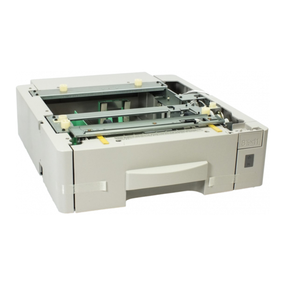
Page 95: Installing Optional Units
INSTALLATION April 5th, 1996 INSTALLING OPTIONAL UNITS 3.3. INSTALLING OPTIONAL UNITS 3.3.1. Printer Interface H516I501.wmf A: 2 screws B: 1 screw H516I503.wmf Put back the rear cover first, then install the brackets [C] and [D]. C: 2 screws D: 2 screws H516I504.wmf Connect the harness [E] first, then install the unit [F]. -
Page 96: Counter
April 5th, 1996 INSTALLATION INSTALLING OPTIONAL UNITS 3.3.2. Counter H516I508.wmf Remove the small cover [B] from the rear cover [A]. A: 2 screws H516I509.wmf Install the counter [C] in the rear cover, connect it to the har- ness from the FDU, then put back the rear cover. -
Page 97: Rs232C Interface
INSTALLATION April 5th, 1996 INSTALLING OPTIONAL UNITS 3.3.4. RS232C Interface H516I505.wmf Remove the small cover [B] from the rear cover [A]. A: 2 screws H516I506.wmf Attach the interface board [C] to the bracket [D]. C: 3 screws H516I507.wmf Attach the interface board as- sembly [E] to the machine, con- nect the harness to the FCE (CN3), then put back the rear... -
Page 98: Service Tables And Procedures
August 2nd, 1995 SERVICE TABLES AND PROCEDURES SERVICE LEVEL FUNCTIONS 4. SERVICE TABLES AND PROCEDURES 4.1. SERVICE LEVEL FUNCTIONS In this section, frequently used keys are referred to with the following symbols. - Start key - Stop key - Function key - Yes key - No key >... -
Page 99: System Parameter List (Function 02)
SERVICE TABLES AND PROCEDURES August 2nd, 1995 SERVICE LEVEL FUNCTIONS 4.1.2. System Parameter List (Function 02) The format of the list is as follows. SYSTEM PARAMETER LIST (Date and Time) * SERIAL NO. - Serial number programmed by function 14) ROM VER. -
Page 100: Error Code Display (Function 03)
August 2nd, 1995 SERVICE TABLES AND PROCEDURES SERVICE LEVEL FUNCTIONS 4.1.3. Error Code Display (Function 03) FUNCTION KPAD/NEXT SERVICE FUNCTIONS then immediately ERROR CODE < > 1-01 JAN 01 17:30 3. Either: Scroll through the error codes - Finish - 4.1.4. -
Page 101: Protocol Dump (Function 05)
SERVICE TABLES AND PROCEDURES August 2nd, 1995 SERVICE LEVEL FUNCTIONS 4.1.5. Protocol Dump (Function 05) FUNCTION KPAD/NEXT SERVICE FUNCTIONS then immediately START PROTOCOL DUMP 4. Finish: 4.1.6. RAM Display/Rewrite (Function 06) FUNCTION KPAD/NEXT SERVICE FUNCTIONS then immediately 0-MEM.R/W 1-MEM.DUMP ADDRESS = 000000 DATA = 00 4. -
Page 102: Ram Dump (Function 06)
August 2nd, 1995 SERVICE TABLES AND PROCEDURES SERVICE LEVEL FUNCTIONS 4.1.7. RAM Dump (Function 06) FUNCTION KPAD/NEXT SERVICE FUNCTIONS then immediately 0-MEM.R/W 1-MEM.DUMP MEMORY DUMP START/N ADD.000000 - 0000FF 4. Enter the first four digits of the start and MEMORY DUMP START/N end addresses . -
Page 103: Ncu Parameters (Function 08)
SERVICE TABLES AND PROCEDURES August 2nd, 1995 SERVICE LEVEL FUNCTIONS (To see the scanned and printed SCAN 012345 PRINT 012345 page counters, press To see the printer and scanner jam count- S.JAM: 000000 P.JAM: 000000 ers, press again.) PM COUNTER: 001234 Check the PM counter - press CTM COUNTER: 001234... -
Page 104: Modem Test (Function 08)
August 2nd, 1995 SERVICE TABLES AND PROCEDURES SERVICE LEVEL FUNCTIONS 4.1.10. Modem Test (Function 08) FUNCTION KPAD/NEXT SERVICE FUNCTIONS then immediately 0-NCU 1-MODEM 2-DTMF 3-DETECT MODEM TEST START/< > 800Hz 4. Scroll through the available tests using 6. To stop the test: 7. -
Page 105: Modem Detection Test (Function 08)
SERVICE TABLES AND PROCEDURES August 2nd, 1995 SERVICE LEVEL FUNCTIONS 4.1.12. Modem Detection Test (Function 08) Note: This function can be used only when G3 bit switch 0B bit 5 (French PTT requirements) is 1 in European models. It cannot be used in USA models. -
Page 106: Operation Panel Test (Function 09)
August 2nd, 1995 SERVICE TABLES AND PROCEDURES SERVICE LEVEL FUNCTIONS 4.1.14. Operation Panel Test (Function 09) FUNCTION KPAD/NEXT SERVICE FUNCTIONS then immediately 0-LED/LCD 5. To stop the test, press 6. To finish: 4.1.15. LED Array Test (Function 10) FUNCTION KPAD/NEXT SERVICE FUNCTIONS then immediately 0-LAMP... -
Page 107: Adf Test (Function 10)
SERVICE TABLES AND PROCEDURES August 2nd, 1995 SERVICE LEVEL FUNCTIONS 4.1.16. ADF Test (Function 10) FUNCTION KPAD/NEXT SERVICE FUNCTIONS then immediately 0-LAMP 1-ADF START 4. Place a document in the feeder, then press 5. To stop the test, press 6. Finish: 4.1.17. -
Page 108: Printer Mechanism Test - Free Run (Function 11)
August 2nd, 1995 SERVICE TABLES AND PROCEDURES SERVICE LEVEL FUNCTIONS 4.1.18. Printer Mechanism Test - Free Run (Function 11) FUNCTION KPAD/NEXT 9 SERVICE FUNCTIONS then immediately 0-PATTERN 1-MECH START MECH 5. To stop the test, press 6. To finish: 4.1.19. RAM Tests (Function 12) FUNCTION KPAD/NEXT SERVICE FUNCTIONS... -
Page 109: Software Download (Function 12)
SERVICE TABLES AND PROCEDURES August 2nd, 1995 SERVICE LEVEL FUNCTIONS 4.1.20. Software Download (Function 12) Instead of replacing an EPROM to update the machine’s software, use this procedure to update the software in the machine’s Flash ROM. This function copies software from an external medium to the Flash ROM on the machine’s FCE. -
Page 110: Software Upload (Function 12)
August 2nd, 1995 SERVICE TABLES AND PROCEDURES SERVICE LEVEL FUNCTIONS If the software is successfully downloaded, the display shows "OK". OK!! COPY MACH <- FLROM If the software download fails, the display shows "NG". NG!! COPY MACH <- FLROM 8. To finish, press 9. -
Page 111: Sram Data Download (Function 12)
SERVICE TABLES AND PROCEDURES August 2nd, 1995 SERVICE LEVEL FUNCTIONS OK!! COPY MACH -> FLROM If the software is successfully uploaded, the display shows "OK". If the software upload fails, the display NG!! shows "NG". COPY MACH -> FLROM 7. Finish : 8. -
Page 112: Serial Number (Function 14)
SERIAL # KPAD 3. Enter the machine’s serial number at the SERIAL # KPAD/Y/N keypad. RICOH 1234567 To correct a mistake: 4. If the display is correct: 5. Finish: 4.1.24. Service Station Fax Number (Function 13) FUNCTION KPAD/NEXT... -
Page 113: Bit Switches
SERVICE TABLES AND PROCEDURES August 2nd, 1995 BIT SWITCHES 4.2. BIT SWITCHES WARNING Do not adjust a bit switch that is described as "Not used", as this may cause the machine to malfunction or to operate in a manner that is not accepted by local regulations. - Page 114 August 2nd, 1995 SERVICE TABLES AND PROCEDURES BIT SWITCHES System Switch 00 FUNCTION COMMENTS Technical data printout on 1: Instead of the personal code, the following data are TCR (Journal) listed on the TCR for each analog G3 communication. 0: Disabled e.g.
- Page 115 SERVICE TABLES AND PROCEDURES August 2nd, 1995 BIT SWITCHES Communication Parameters Mode DCS: ITU-T standard NSS: Non-standard G3 Modem rate 144: 14400 bps 120: 12000 bps 96: 9600 bps 72: 7200 bps 48: 4800 bps 24: 2400 bps Communication ECM: With ECM SSC: Using SSC mode EFC: Using EFC NML: With no ECM, SSC, or EFC Compression...
- Page 116 August 2nd, 1995 SERVICE TABLES AND PROCEDURES BIT SWITCHES System Switch 02 FUNCTION COMMENTS Memory file transfer 1: All messages in the memory (including confidential 0: Disabled rx messages) are sent to the fax number which is 1: Enabled programmed as the service station. Always reset this bit to zero after transfer.
- Page 117 SERVICE TABLES AND PROCEDURES August 2nd, 1995 BIT SWITCHES System Switch 03 FUNCTION COMMENTS Length of time that RDS is 00 - 99 hours (BCD). temporarily switched on when bits 6 and 7 of This data is only valid if bits 6 and 7 of System Switch System Switch 02 are set to 02 are set to "User selectable".
- Page 118 August 2nd, 1995 SERVICE TABLES AND PROCEDURES BIT SWITCHES System Switch 05 FUNCTION COMMENTS Not used Do not change the settings. Display of both RTI and CSI 1: Both RTI and CSI will be displayed alternately on on the LCD the LCD.
- Page 119 SERVICE TABLES AND PROCEDURES August 2nd, 1995 BIT SWITCHES System Switch 09 FUNCTION COMMENTS Priority given to various This bit determines which set of priorities the machine types of remote terminal ID uses when listing remote terminal names on reports. when printing reports 0: RTI >...
- Page 120 August 2nd, 1995 SERVICE TABLES AND PROCEDURES BIT SWITCHES System Switch 0C - Not used (do not change the settings) System Switch 0D - Not used (do not change the settings) System Switch 0E - Not used (do not change the settings) System Switch 0F FUNCTION COMMENTS...
- Page 121 System Switch 15 FUNCTION COMMENTS Wording setting 0: Ricoh 1: Siemens - Set this bit to 1 for Siemens wording on the LCD panel. Not used Do not change the settings. System Switch 15 - Not used (do not change the settings)
-
Page 122: Scanner Switches
August 2nd, 1995 SERVICE TABLES AND PROCEDURES BIT SWITCHES 4.2.2. Scanner Switches Scanner Switch 00 FUNCTION COMMENTS Not used Do not change the settings. Not used Do not change the settings. Maximum transmittable If the user wants to send very long documents such as document length well logs, select 14 m or a higher setting. - Page 123 SERVICE TABLES AND PROCEDURES August 2nd, 1995 BIT SWITCHES Scanner Switch 05 FUNCTION COMMENTS Contrast threshold with The value can be between 00 to 0F. For a darker halftone enabled - Normal threshold, input a lower value. setting Default setting - 07(H) Scanner Switch 06 FUNCTION COMMENTS...
-
Page 124: Printer Switches
August 2nd, 1995 SERVICE TABLES AND PROCEDURES BIT SWITCHES 4.2.3. Printer Switches Printer Switch 00 FUNCTION COMMENTS Page separation mark 0: No marks are printed. 0: Disabled 1: If a received page has to be printed out on two 1: Enabled sheets, an "x"... - Page 125 SERVICE TABLES AND PROCEDURES August 2nd, 1995 BIT SWITCHES Printer Switch 03 FUNCTION COMMENTS Length reduction of 0: Incoming pages are printed without length received data reduction. 0: Disabled Cross reference 1: Enabled Page separation threshold: Printer Sw. 03, bits 4 to 7. 1: Incoming pages are reduced in the length direction when printing.
- Page 126 August 2nd, 1995 SERVICE TABLES AND PROCEDURES BIT SWITCHES Printer Switches 04 and 05 FUNCTION COMMENTS Reduction ratios used for different paper sizes (with reduction enabled in switch 03-0 above) If reduction is enabled, the data will be reduced in the length direction before printing. These switches determine the maximum reduction ratio for each paper size.
-
Page 127: Communication Switches
SERVICE TABLES AND PROCEDURES August 2nd, 1995 BIT SWITCHES 4.2.4. Communication Switches Communication Switch 00 FUNCTION COMMENTS Compression modes These bits determine the compression capabilities to available in receive mode be declared in phase B (handshaking) of the T.30 Bit 1 Modes protocol. - Page 128 August 2nd, 1995 SERVICE TABLES AND PROCEDURES BIT SWITCHES Communication Switch 01 FUNCTION COMMENTS If this bit is 0, ECM is switched off for all 0: Off 1: On communications. EFC during transmission If this bit is 0, EFC is switched off during transmission. 0: Off 1: On Wrong connection (0,1) - The machine will not transmit if the last 8 digits...
- Page 129 SERVICE TABLES AND PROCEDURES August 2nd, 1995 BIT SWITCHES Communication Switch 02 FUNCTION COMMENTS Burst error threshold If there are more consecutive error lines in the 0: Low 1: High received page than the threshold, the machine will send a negative response. The Low and High threshold values depend on the sub-scan resolution, and are as follows.
- Page 130 August 2nd, 1995 SERVICE TABLES AND PROCEDURES BIT SWITCHES Communication Switch 06 FUNCTION COMMENTS Dialing requirements: These switches are automatically set to the settings Germany required by each country after a country code (System 0: Disabled 1: Enabled Switch 0F) is programmed. Dialing requirements: Austria 0: Disabled 1: Enabled Dialing requirements:...
- Page 131 SERVICE TABLES AND PROCEDURES August 2nd, 1995 BIT SWITCHES Communication Switch 0D FUNCTION COMMENTS The amount of remaining 00 to FF (Hex), unit = 2 kbytes memory below which (e.g., 0C(H) = 24 kbytes) ringing detection (and One page is about 24 kbytes. therefore reception into If this setting is kept at 0, the machine will detect memory) is disabled...
- Page 132 August 2nd, 1995 SERVICE TABLES AND PROCEDURES BIT SWITCHES Communication Switch 13 FUNCTION COMMENTS Immediate transmission: 00 - FF (Hex) minutes Interval between dialing attempts to the same destination Communication Switch 14 - Not used (do not change the settings) Communication Switch 15 - Not used (do not change the settings) Communication Switch 16 - Not used (do not change the settings) Communication Switch 17 - Not used (do not change the settings)
-
Page 133: G3 Switches
SERVICE TABLES AND PROCEDURES August 2nd, 1995 BIT SWITCHES 4.2.5. G3 Switches G3 Switch 00 FUNCTION COMMENTS Monitor speaker during (0, 0): The monitor speaker is disabled all through the communication (tx and rx) communication. Bit 1 Bit 0 Setting (0, 1): The monitor speaker is on up to phase B in the Disabled T.30 protocol. - Page 134 CTC transmission conditions When using ECM, the machine will choose a slower 0: Ricoh mode (PPR x 1) modem rate after receiving PPR once (Ricoh mode) or 1: ITU-T mode (PPR x 4) four times (ITU-T mode). ITU-T: New acronym for the CCITT.
- Page 135 SERVICE TABLES AND PROCEDURES August 2nd, 1995 BIT SWITCHES G3 Switch 04 FUNCTION COMMENTS Training error detection 0 - F (Hex); 0 - 15 bits threshold If the number of error bits in the received TCF is below this threshold, the machine informs the sender that the training has succeeded.
- Page 136 August 2nd, 1995 SERVICE TABLES AND PROCEDURES BIT SWITCHES G3 Switch 07 FUNCTION COMMENTS PSTN cable equalizer Use a higher setting if there is signal loss at higher (tx mode) frequencies because of the length of wire between the Bit 1 Bit 0 Setting modem and the telephone exchange.
- Page 137 SERVICE TABLES AND PROCEDURES August 2nd, 1995 BIT SWITCHES G3 Switch 0A FUNCTION COMMENTS Maximum allowable carrier These bits set the acceptable modem carrier drop time. drop during image data Try using a longer setting if error code 0-22 is frequent. reception Bit 1 Bit 0...
- Page 138 August 2nd, 1995 SERVICE TABLES AND PROCEDURES BIT SWITCHES G3 Switch 0C FUNCTION COMMENTS Pulse dialing method P = Number of pulses sent out, N = Number dialed. Bit 1 Bit 0 Setting Normal (P=N) Oslo (P=10 - N) Sweden (N+1) Not used Not used Do not change the settings.
-
Page 139: Ncu Parameters *
SERVICE TABLES AND PROCEDURES August 2nd, 1995 NCU PARAMETERS * 4.3. NCU PARAMETERS * The following tables give the RAM addresses and units of calculation of the parameters that the machine uses for ringing signal detection and automatic dialing. The factory settings for each country are also given. Most of these must be changed by RAM read/write (Function 06), but some can be changed using NCU Parameter programming (Function 08);... - Page 140 August 2nd, 1995 SERVICE TABLES AND PROCEDURES NCU PARAMETERS * Address Function Unit Remarks 807F06 Not used Do not change the factory setting. 807F07 807F08 PSTN dial tone detection time 20 ms If 807F08 contains FF, the machine pauses for the 807F09 PSTN dial tone reset time (LOW) pause time (address...
- Page 141 SERVICE TABLES AND PROCEDURES August 2nd, 1995 NCU PARAMETERS * Address Function Unit Remarks PABX detection time for silent 20 ms 807F24 period after ringback tone detected (LOW) PABX detection time for silent 20 ms period after ringback tone 807F25 detected (HIGH) PABX busy tone frequency range Hz (BCD)
- Page 142 August 2nd, 1995 SERVICE TABLES AND PROCEDURES NCU PARAMETERS * Address Function Unit Remarks International dial tone detection 20 ms If 807F38 contains FF, the 807F38 time machine pauses for the pause time (807F3D / International dial tone reset time 807F39 807F3E).
- Page 143 SERVICE TABLES AND PROCEDURES August 2nd, 1995 NCU PARAMETERS * Address Function Unit Remarks Tone attenuation value in DTMF -dBm x Function 08 (parameter 19). 807F52 signals See Note 6. Tone attenuation value difference -Nx0.5 Function 08 (parameter 20). between high frequency tone and (dB) See Note 6.
- Page 144 August 2nd, 1995 SERVICE TABLES AND PROCEDURES NCU PARAMETERS * Address Function Unit Remarks Acceptable ringing signal 1000/ N Function 08 (parameter 02). 807F72 frequency: range 1, upper limit (Hz). Acceptable ringing signal Function 08 (parameter 03). 807F73 frequency: range 1, lower limit Acceptable ringing signal Function 08 (parameter 04).
- Page 145 SERVICE TABLES AND PROCEDURES August 2nd, 1995 NCU PARAMETERS * Address Function Unit Remarks 807FA6 Not used Do not change the factory setting. 807FA7 807FA8 807FA9 CNG detection time 20 ms Factory setting: 200 ms 807FAA ± 20 ms CNG on time 20 ms Factory setting: 500 ms 807FAB...
- Page 146 August 2nd, 1995 SERVICE TABLES AND PROCEDURES NCU PARAMETERS * Notes 1. If a setting is not required, store FF in the address. 2. Tone frequencies are stored as look-up tables in hex code. For each pa- rameter, there is a look-up table for each country that uses it. The tables are given following this page.
- Page 147 SERVICE TABLES AND PROCEDURES August 2nd, 1995 NCU PARAMETERS * Tone Detection Frequency Ranges - PSTN Dial Tone (807F04 - 807F05) - France Germany Italy RAM Value RAM Value RAM Value Range (Hz) Range (Hz) Range (Hz) 415 - 465 400 - 480 030 (Default) 410 - 440...
- Page 148 August 2nd, 1995 SERVICE TABLES AND PROCEDURES NCU PARAMETERS * Switzerland Portugal Holland RAM Value RAM Value RAM Value Range (Hz) Range (Hz) Range (Hz) 385 - 560 315 - 440 290 - 580 380 - 565 305 - 450 280 - 585 370 - 570 0B0 (Default)
- Page 149 SERVICE TABLES AND PROCEDURES August 2nd, 1995 NCU PARAMETERS * Sweden Switzerland Australia RAM Value RAM Value RAM Value Range (Hz) Range (Hz) Range (Hz) FFFF Tone not 380 - 465 385 - 560 (Default) detected 375 - 470 380 - 565 405 - 445 365 - 475 370 - 570...
- Page 150 August 2nd, 1995 SERVICE TABLES AND PROCEDURES NCU PARAMETERS * - PSTN Busy Tone (807F13 - 807F14) France Germany U. K. RAM Value RAM Value RAM Value Range (Hz) Range (Hz) Range (Hz) 415 - 465 400 - 480 330 - 470 410 - 470 390 - 485 320 - 460...
- Page 151 SERVICE TABLES AND PROCEDURES August 2nd, 1995 NCU PARAMETERS * Sweden Switzerland Holland RAM Value RAM Value RAM Value Range (Hz) Range (Hz) Range (Hz) 030 (Default) 410 - 440 385 - 560 335 - 540 400 - 450 380 - 565 325 - 545 395 - 455 370 - 570...
- Page 152 August 2nd, 1995 SERVICE TABLES AND PROCEDURES NCU PARAMETERS * - PABX Busy Tone (807F26 - 807F27) Italy Denmark Switzerland, Israel RAM Value RAM Value RAM Value Range (Hz) Range (Hz) Range (Hz) 030 (Default) 410 - 440 405 - 445 385 - 560 400 - 450 415 - 455...
-
Page 153: Default Settings
SERVICE TABLES AND PROCEDURES August 2nd, 1995 NCU PARAMETERS * Default Settings * The factory settings are quoted either in hexadecimal code (the actual con- tents of the RAM address) if there is a H after the value in the table, or in decimal (converted from the actual hex contents of the RAM address) if there is no H after the value. - Page 154 August 2nd, 1995 SERVICE TABLES AND PROCEDURES NCU PARAMETERS * Country 807F06 807F07 807F08 807F09 807F0A France Germany Italy Austria Belgium Denmark Finland Ireland Norway Sweden Switzerland Portugal Holland Spain Israel Asia Hong Kong South Africa Australia New Zealand Singapore Malaysia Country 807F0B...
- Page 155 SERVICE TABLES AND PROCEDURES August 2nd, 1995 NCU PARAMETERS * Country 807F10 807F11 807F12 807F13 807F14 France Germany Italy Austria Belgium Denmark Finland Ireland Norway Sweden Switzerland Portugal Holland Spain Israel Asia Hong Kong South Africa Australia New Zealand Singapore Malaysia Country 807F15...
- Page 156 August 2nd, 1995 SERVICE TABLES AND PROCEDURES NCU PARAMETERS * Country 807F1C 807F1D 807F1E 807F1F 807F20 France Germany Italy Austria Belgium Denmark Finland Ireland Norway Sweden Switzerland Portugal Holland Spain Israel Asia Hong Kong South Africa Australia New Zealand Singapore Malaysia Country 807F21...
- Page 157 SERVICE TABLES AND PROCEDURES August 2nd, 1995 NCU PARAMETERS * Country 807F26 807F27 807F28 807F29 807F2A France Germany Italy Austria Belgium Denmark Finland Ireland Norway Sweden Switzerland Portugal Holland Spain Israel Asia Hong Kong South Africa Australia New Zealand Singapore Malaysia Country 807F2B...
- Page 158 August 2nd, 1995 SERVICE TABLES AND PROCEDURES NCU PARAMETERS * Country 807F30 807F31 807F32 807F33 807F34 France Germany Italy Austria Belgium Denmark Finland Ireland Norway Sweden Switzerland Portugal Holland Spain Israel Asia Hong Kong South Africa Australia New Zealand Singapore Malaysia Country 807F35...
- Page 159 SERVICE TABLES AND PROCEDURES August 2nd, 1995 NCU PARAMETERS * Country 807F3A 807F3B 807F3C 807F3D 807F3E France Germany Italy Austria Belgium Denmark Finland Ireland Norway Sweden Switzerland Portugal Holland Spain Israel Asia Hong Kong South Africa Australia New Zealand Singapore Malaysia Country 807F3F...
- Page 160 August 2nd, 1995 SERVICE TABLES AND PROCEDURES NCU PARAMETERS * Country 807F44 807F45 807F46 807F47 807F48 France Germany Italy Austria Belgium Denmark Finland Ireland Norway Sweden Switzerland Portugal Holland Spain Israel Asia Hong Kong South Africa Australia New Zealand Singapore Malaysia Country 807F49...
- Page 161 SERVICE TABLES AND PROCEDURES August 2nd, 1995 NCU PARAMETERS * Country 807F4E 807F4F 807F50 807F51 807F52 France Germany Italy Austria Belgium Denmark Finland Ireland Norway Sweden Switzerland Portugal Holland Spain Israel Asia Hong Kong South Africa Australia New Zealand Singapore Malaysia Country 807F53...
- Page 162 August 2nd, 1995 SERVICE TABLES AND PROCEDURES NCU PARAMETERS * Country 807F5C 807F5D 807F5E 807F5F 807F65 France Germany Italy Austria Belgium Denmark Finland Ireland Norway Sweden Switzerland Portugal Holland Spain Israel Asia Hong Kong South Africa Australia New Zealand Singapore Malaysia Country 807F66...
- Page 163 SERVICE TABLES AND PROCEDURES August 2nd, 1995 NCU PARAMETERS * Country 807F76 807F77 807F78 807F79 807F7A France Germany Italy Austria Belgium Denmark Finland Ireland Norway Sweden Switzerland Portugal Holland Spain Israel Asia Hong Kong South Africa Australia New Zealand Singapore Malaysia Country 807F81...
- Page 164 August 2nd, 1995 SERVICE TABLES AND PROCEDURES NCU PARAMETERS * Country 807FA4 807FA5 807FA6 807FA7 807FA8 France Germany Italy Austria Belgium Denmark Finland Ireland Norway Sweden Switzerland Portugal Holland Spain Israel Asia Hong Kong South Africa Australia New Zealand Singapore Malaysia Country 807FA9...
- Page 165 SERVICE TABLES AND PROCEDURES August 2nd, 1995 NCU PARAMETERS * Country 807FAE 807FAF 807FB1 807FB2 807FB3 France Germany Italy Austria Belgium Denmark Finland Ireland Norway Sweden Switzerland Portugal Holland Spain Israel Asia Hong Kong South Africa Australia New Zealand Singapore Malaysia Country 807FB4...
- Page 166 August 2nd, 1995 SERVICE TABLES AND PROCEDURES NCU PARAMETERS * Country 807FB9 807FBD 807FDA France Germany Italy Austria Belgium Denmark Finland Ireland Norway Sweden Switzerland Portugal Holland Spain Israel Asia Hong Kong South Africa Australia New Zealand Singapore Malaysia 4-69...
-
Page 167: Dedicated Transmission Parameters
SERVICE TABLES AND PROCEDURES August 2nd, 1995 DEDICATED TRANSMISSION PARAMETERS 4.4. DEDICATED TRANSMISSION PARAMETERS Each Quick Dial Key and Speed Dial Code has four bytes of programmable parameters allocated to it. If transmissions to a particular machine often expe- rience problems, store that terminal’s fax number as a Quick Dial or Speed Dial, and adjust the parameters allocated to that number. -
Page 168: Parameters
August 2nd, 1995 SERVICE TABLES AND PROCEDURES DEDICATED TRANSMISSION PARAMETERS 4.4.2. Parameters The initial settings of the following parameters are all FF(H) - all the parame- ters are disabled. Byte 0 FUNCTION AND COMMENTS CCITT T1 time If the connection time to a particular terminal is longer than the NCU parameter setting , adjust this byte. - Page 169 SERVICE TABLES AND PROCEDURES August 2nd, 1995 DEDICATED TRANSMISSION PARAMETERS Byte 2 FUNCTION COMMENTS Initial Tx modem rate If training with a particular remote Bit 3 Setting (bps) terminal always takes too long, the Not used initial modem rate may be too high. 2,400 Reduce the initial Tx modem rate 4,800...
-
Page 170: Service Ram Addresses *
August 2nd, 1995 SERVICE TABLES AND PROCEDURES SERVICE RAM ADDRESSES 4.5. SERVICE RAM ADDRESSES CAUTION Do not change the settings which are marked as “Not used” or “Read only.” 800000(H) - RAM Reset Level 1 Change the data at this address to 00 (H), then switch the machine off and on to reset all the system settings. - Page 171 SERVICE TABLES AND PROCEDURES August 2nd, 1995 SERVICE RAM ADDRESSES 8000A2(H) - User parameter switch 02 * Bit 0: Forwarding mark printing on forwarded messages 0: Disabled, 1: Enabled Bit 1: Center mark printing on received copies 0: Disabled, 1: Enabled Bit 2: Reception time printing 0: Disabled, 1: Enabled Bit 3: TSI included in transmitted messages...
- Page 172 August 2nd, 1995 SERVICE TABLES AND PROCEDURES SERVICE RAM ADDRESSES 8000A8(H) - User parameter switch 08 * Bit 0 and 1: Multi-copy reception (optional memory card required) Setting Disabled Faxes from senders whose RTIs/CSIs are specified for this feature are multicopied.
- Page 173 SERVICE TABLES AND PROCEDURES August 2nd, 1995 SERVICE RAM ADDRESSES 8000AC(H) - User parameter switch 12 Bits 0 and 1: Not used Bit 2: Toner saving mode 0: Disabled, 1: Enabled Bits 3 and 4: Printout image density (Fax mode) Setting Normal Lighten...
- Page 174 August 2nd, 1995 SERVICE TABLES AND PROCEDURES SERVICE RAM ADDRESSES 80012F(H) - ID code (low - Hex) 800130(H) - ID code (high - Hex) 800131(H) - Confidential ID (low - BCD) 800132(H) - Confidential ID (high - BCD) 800133(H) - Memory lock ID (low - Hex) 800134(H) - Memory lock ID (high - Hex) 800140 to 800146(H) - Last power off time (Read only) 800140(H) - Year (BCD)
- Page 175 SERVICE TABLES AND PROCEDURES August 2nd, 1995 SERVICE RAM ADDRESSES 800179 to 80017B(H) - Printer total jam counter (COPY JAM) 80017C to 80017E(H) - Paper jam counter: standard cassette (UPPER CST JAM) * 80017F to 800181(H) - Paper jam counter: optional PFU (CST 2 JAM) 800182 to 800184(H) - Paper jam counter: optional 100 sheet cassette (OPEN CST JAM) 800188 to 80018A(H) - Scanner total jam counter (DOC.
- Page 176 August 2nd, 1995 SERVICE TABLES AND PROCEDURES SERVICE RAM ADDRESSES 80024D(H) - Daylight saving time setting (User function 62) 800250(H) - Transmission monitor volume 00 - 07(H) 800251(H) - Reception monitor volume 00 - 07(H) 800252(H) - On-hook monitor volume 00 - 07(H) 800254(H) - Buzzer volume 00 - 07(H)
- Page 177 SERVICE TABLES AND PROCEDURES August 2nd, 1995 SERVICE RAM ADDRESSES 80033D(H) - Excessive jam alarm Bit 3: Scanner excessive jam alarm 1: An alarm has occurred Bit 4: Printer excessive jam alarm 1: An alarm has occurred Either or both of these bits will change to 1 when an excessive jam alarm occurs. Reset each bit to 0 when you have solved the problem.
- Page 178 August 2nd, 1995 SERVICE TABLES AND PROCEDURES SERVICE RAM ADDRESSES 8003B2(H) - Sensor status (optional 100 sheet cassette) Bit 0 to 3: Paper size sensor (Note: Available paper sizes depend on the country for which the machine is designed.) ...
- Page 179 SERVICE TABLES AND PROCEDURES August 2nd, 1995 SERVICE RAM ADDRESSES 8003B5(H) - Details of the service call (hardware error) 01(H) - The fusing lamp temperature stayed above 175 °C while printing. 02(H) - The fusing lamp temperature did not reach 150 °C before starting printing. 03(H) - The fusing lamp temperature did not go down to 80 °C while in standby mode (when fusing lamp OFF was selected for power saver mode) 04(H) - The fusing lamp temperature did not go down to 80 °C while in standby mode (when...
- Page 180 August 2nd, 1995 SERVICE TABLES AND PROCEDURES SERVICE RAM ADDRESSES 8003FD to 800404 (H) - Scanner Video Processing Parameters Bit no. Mode Resolution The functions of each bit are Address described below this table. Standard 8003FD(H) (Memory tx) Standard Text 8003FE(H) (Immediate tx) Detail...
- Page 181 SERVICE TABLES AND PROCEDURES August 2nd, 1995 SERVICE RAM ADDRESSES 803B88 to 803D9A(H) - Latest 10 error communication records One error communication record consists of 53 bytes. The format is as follows: 1st byte - Header Bit 0: Communication result 0: OK, 1: NG Bit 1: Document jam 1: Occurred...
- Page 182 August 2nd, 1995 SERVICE TABLES AND PROCEDURES SERVICE RAM ADDRESSES 16th byte to 35th byte - Remote terminal’s ID (RTI, TSI or CSI) (ASCII) 36th byte - Communication mode #1 Bits 0 - 1: Resolution used = : Standard , ...
-
Page 183: Special Tools And Lubricants
SERVICE TABLES AND PROCEDURES August 2nd, 1995 SPECIAL TOOLS AND LUBRICANTS 4.6. SPECIAL TOOLS AND LUBRICANTS • Flash/SRAM data copy harness (P/N: H5159100) 4.7. PM TABLE Scanner Item 1 year Notes Exposure Glass C (user) C (user) C (user) C (user) Soft cloth and water R1 and R2 Rollers Soft cloth and water... -
Page 184: Covers
August 2nd, 1995 REPLACEMENT AND ADJUSTMENT COVERS 5. REPLACEMENT AND ADJUSTMENT WARNING The machine contains a laser beam generator. Laser beams can cause permanent eye damage. Do not open the laser unit or look along the laser beam path while the main power is on. CAUTION Before starting disassembly, be sure to print all message files in the SAF memory. -
Page 185: Rear Cover Assembly
REPLACEMENT AND ADJUSTMENT August 2nd, 1995 COVERS 5.1.2. Rear Cover Assembly H516R502.wmf A: Rear Cover (2 screws, 3 hooks) 5.1.3. Left Cover H516R503.wmf A: Cover (1 screw) B: Left Cover (2 screws, 3 hooks, 1 connector) -
Page 186: Right Cover
August 2nd, 1995 REPLACEMENT AND ADJUSTMENT COVERS 5.1.4. Right Cover H516R504.wmf A: Small Cover (1 screw) B: Right Cover (2 screws, 3 hooks) 5.1.5. Operation Panel Assembly H516R505.wmf A: Scanner Side Cover (1 screw) B: Bracket (1 tapping screw) C: Operation Panel Assembly (1 tapping screw with ground wire, 1 connector) -
Page 187: Operation Panel And Adf Upper Unit
REPLACEMENT AND ADJUSTMENT August 2nd, 1995 COVERS 5.1.6. Operation Panel and ADF Upper Unit H516R506.wmf A: Operation Panel Assembly (5 screws, 1 grounding wire, 3 connectors) B: ADF Upper Unit 5.1.7. Top Cover H516R507.wmf A: Top Cover (1 white clip) -
Page 188: Operation Panel
August 2nd, 1995 REPLACEMENT AND ADJUSTMENT OPERATION PANEL 5.2. OPERATION PANEL 5.2.1. Operation Panel and OPU H516R508.wmf A: Operation Panel B: OPU 5.3. ADF 5.3.1. ADF Roller Assembly H516R509.wmf A: ADF Roller Cover B: ADF Roller Assembly... -
Page 189: Separation Rubber Plate
REPLACEMENT AND ADJUSTMENT August 2nd, 1995 5.3.2. Separation Rubber Plate H516R510.wmf A: Separation Rubber Plate 5.3.3. Separation Pressure Adjustment To match the paper type that the user will be scanning, adjust the position of lever [A] as shown in the following table. Paper Pressure Position... -
Page 190: Adf Sensors
August 2nd, 1995 REPLACEMENT AND ADJUSTMENT 5.3.4. ADF Sensors H516R512.wmf A: Document Sensor B: Bracket (6 tapping screws) C: Scan Line Sensor 5.3.5. Scanner Shading Plate H516R513.wmf A, B: Clips C: Shading Plate D, E: Springs... -
Page 191: Scanner
REPLACEMENT AND ADJUSTMENT August 2nd, 1995 SCANNER 5.4. SCANNER 5.4.1. Scanner Unit Disassembly H516R514.wmf A: Scanner Side Cover (1 screw) B: Scanner Lower Unit (5 screws, 4 of which are tapping screws; 2 connectors) 5.4.2. Tx Motor and Drive Components H516R515.wmf A: Tx Motor (2 screws, 1 connector) Continued on the next page. -
Page 192: R1/R2 Rollers
August 2nd, 1995 REPLACEMENT AND ADJUSTMENT SCANNER Drive Components First remove the belt tensioning pulley [A], then remove the scanner drive gear train [B] and the belt [C]. Note: Do not forget the plastic spacer [D] when reassembling. H516R516.wmf A: Belt Tensioning Pulley (1 screw) B: Scanner Drive Gear Train (3 tapping screws) C: Scanner Drive Belt D: Spacer... -
Page 193: Contact Image Sensor
REPLACEMENT AND ADJUSTMENT August 2nd, 1995 SCANNER 5.4.4. Contact Image Sensor H516R518.wmf A: Bracket (3 tapping screws) B: Contact Image Sensor Assembly (1 connector, 2 tapping screws with washers, 2 spring plates) C/D: Spacers (3 hooks each) First remove the bracket [A], then remove the Contact Image Sensor [B]. CAUTION Do not remove the brackets [E] and [F]. -
Page 194: Laser Printing Components
August 2nd, 1995 REPLACEMENT AND ADJUSTMENT LASER PRINTING COMPONENTS 5.5. LASER PRINTING COMPONENTS 5.5.1. Laser Unit First, remove the clip [A] and disconnect harnesses [B], [C] and [D], then re- move the Laser Unit [E]. H516R519.wmf E: Laser Unit (1 clip, 3 connectors, 4 positioning pins) 5-11... -
Page 195: Laser Diode Unit And Hexagonal Mirror Motor
REPLACEMENT AND ADJUSTMENT August 2nd, 1995 LASER PRINTING COMPONENTS 5.5.2. Laser Diode Unit and Hexagonal Mirror Motor H516R520.wmf A: Laser Unit Cover B: Laser Diode (LD) Unit (2 tapping screws) C: Hexagonal Mirror Motor (3 tapping screws) WARNING Laser beams can cause permanent eye damage. Do not open the laser unit or look along the laser beam path while the main power is on. -
Page 196: Development
August 2nd, 1995 REPLACEMENT AND ADJUSTMENT DEVELOPMENT 5.6. DEVELOPMENT 5.6.1. Development Unit [B, C] H516R521.wmf Release the clips [B] and [C] and remove the main motor cover [D], then remove the development unit [A]. A: Development Unit (2 clips, 1 connector) Note for disassembly [B’... -
Page 197: Transfer Roller
REPLACEMENT AND ADJUSTMENT August 2nd, 1995 DEVELOPMENT 5.6.2. Transfer Roller H516R522.wmf A: Transfer Roller (1 gear, 2 spacers) 5.6.3. Main Motor and Gears First, remove the zener diode [A], then remove the main motor assembly [B]. Note: Once the main motor assembly is removed, the gears and the shafts will come off the unit easily. -
Page 198: Replacing The Development Unit
August 2nd, 1995 REPLACEMENT AND ADJUSTMENT DEVELOPMENT 5.6.4. Replacing the Development Unit H516R546.wmf A: Development Unit B: Development Roller (Rubber) C: Pin D: Development Roller Gear E, F: Bushings After every 60,000 prints, the following parts have to be replaced. •... - Page 199 REPLACEMENT AND ADJUSTMENT August 2nd, 1995 DEVELOPMENT 3. Check the electrical resistance of the following. Charge bias terminals/Zener diode H516R556.wmf A: Bias terminal to the CTM B: Bias terminal from the power pack C, D: Zener diode terminals Criteria A - B: 0 Ω C - D: The resistance varies depending on the voltage applied between termi- nals.
- Page 200 August 2nd, 1995 REPLACEMENT AND ADJUSTMENT DEVELOPMENT 4. Install the new development unit into the machine. 5. Install the drum and CTM, and check that the following points are con- nected to the frame ground. • Drum shaft • Main motor bracket •...
-
Page 201: Fusing
REPLACEMENT AND ADJUSTMENT August 2nd, 1995 FUSING 5.7. FUSING 5.7.1. Thermistor H516R524.wmf A: Thermistor Cover (6 hooks) B: Thermistor (1 tapping screw, 1 connector) 5.7.2. Fusing Unit Preparation - Right hand side First, open the fusing exit cover, then remove the sensor assembly [A], bracket [B], and gear [C]. - Page 202 August 2nd, 1995 REPLACEMENT AND ADJUSTMENT FUSING Preparation - Left hand side Note: Put back the bracket [D] after removing the ground wire [A]. H516R526.wmf A: Fusing Left Cover (1 tapping screw) B: Harness Cover A (1 tapping screw) C: Harness Cover B (1 tapping screw) D: Ground Wire (1 screw) E: Fusing Unit Fulcrum (1 tapping screw) F: Thermistor Harness...
-
Page 203: Hot Roller Strippers
REPLACEMENT AND ADJUSTMENT August 2nd, 1995 FUSING 5.7.3. Hot Roller Strippers H516R528.wmf A: Cleaning Felt B: Hot Roller Strippers (1 spring each) Remove the cleaning felt if it is still in the unit, then remove the strippers. CAUTION Be careful not to lose the springs. 5.7.4. -
Page 204: Hot Roller
August 2nd, 1995 REPLACEMENT AND ADJUSTMENT FUSING 5.7.5. Hot Roller H516R530.wmf First, remove the tapping screw [A], then remove the tapping screws [B] and [C]. The fusing upper and lower units come apart after the ground plate [D] is released from the upper unit [E]. CAUTION: Do not bend the ground plate too much. - Page 205 REPLACEMENT AND ADJUSTMENT August 2nd, 1995 FUSING Remove the bracket [A], then remove the hot roller [B]. H516R531.wmf 115V Models A: Bracket (3 screws, 2 of which are tapping screws) B: Hot Roller C: Fusing Lamp Connector (1 screw) H516R553.wmf 220V Models A: Bracket (3 screws, 2 of which are tapping screws) B: Hot Roller...
-
Page 206: Pressure Roller
August 2nd, 1995 REPLACEMENT AND ADJUSTMENT FUSING 5.7.6. Pressure Roller H516R532.wmf A: Bracket (2 screws, 1 of which is a stepped screw) B: Bracket (1 tapping screw) C: Pressure Roller 5.7.7. Thermostat and Thermofuse H516R554.wmf A: Thermostat (2 screws) B: Thermofuse (2 screws) - 220V models only C, D - Terminal Plates for the Thermfuse - 220V models only 5-23... -
Page 207: Paper Feed
REPLACEMENT AND ADJUSTMENT August 2nd, 1995 PAPER FEED 5.8. PAPER FEED 5.8.1. Paper Feed Motor and Clutch Box H516R534.wmf A: Paper Feed Motor (2 screws) B: Paper Feed Clutch Box (1 clip, 2 screws) 5.8.2. Paper End Sensor First, remove the bracket [A], then remove the sensor [B]. H516R535.wmf A: Bracket (1 screw) B: Paper End Sensor... -
Page 208: Paper Feed Rollers, Paper Size Sensor, And Relay Connector
August 2nd, 1995 REPLACEMENT AND ADJUSTMENT PAPER FEED 5.8.3. Paper Feed Rollers, Paper Size Sensor, and Relay Connector H516R536.wmf A: Feed rollers (1 screw each) B: Paper size sensor (2 hooks, 1 connector) C: Relay connector to the optional 100 sheet cassette (1 screw, 1 connector) Paper feed rollers [A]: Turn the roller shaft as shown in the diagram, so that the screw heads can seen from the front. -
Page 209: Registration Roller And Bypass Feed Sensor
REPLACEMENT AND ADJUSTMENT August 2nd, 1995 PAPER FEED 5.8.4. Registration Roller and Bypass Feed Sensor H516R537.wmf A: Paper guide A (4 hooks) B: Paper guide B (4 hooks) C, D: Springs E: Registration roller (1 E-ring, 1 gear) F: Bracket (2 tapping screws) G: Guide plate (5 hooks) H: Bypass feed sensor actuator (2 hooks) Registration Roller... -
Page 210: Pcbs
August 2nd, 1995 REPLACEMENT AND ADJUSTMENT PCBs 5.9. PCBs 5.9.1. PSU and NCU H516R538.wmf A: NCU (3 screws) B: PSU Cover (3 screws) C: PSU (3 screws, 3 connectors) 5.9.2. NCU, FDU, and FCE H516R539.wmf A: NCU (3 screws) B: FDU (2 screws) C: FCE (2 screws) After installing the new FCE, transfer the RAM data from the old FCE using service function 12 (refer to section 4.1.22). -
Page 211: Power Pack
REPLACEMENT AND ADJUSTMENT August 2nd, 1995 PCBs Harness Connections from the FDU Main Motor Quenching 100 Sheet Stamp Paper Feed Lamp Tx Motor Cassette Ozone Fan Power Pack Motor Fan Motor (Optional) Speaker Not Used Mech. Counter CN63 CN15 CN62 CN17 CN20 CN18... -
Page 212: Others
August 2nd, 1995 REPLACEMENT AND ADJUSTMENT OTHERS 5.10. OTHERS 5.10.1. Ozone Filter and Fan Motor H516R541.wmf A, B: Ozone Filter Holder (2 screws) C: Ozone Filter D: Fan Motor (1 connector) Remove the bracket [A], then the ozone filter [B] and the fan motor [C] can be removed. -
Page 213: Paper End Sensor And Drive Components
REPLACEMENT AND ADJUSTMENT August 2nd, 1995 100 SHEET PAPER CASSETTE (OPTIONAL) 5.11.2. Paper End Sensor and Drive Components H516R543.wmf A: Sensor Stay (1 hook) B: Sensor Cover (2 hooks) C: Paper End Sensor (3 hooks) D: Idle Gears (1 clip each) E: Paper Feed Clutch (1 clip) F: Feed Roller (2 bushings, 1 clip) -
Page 214: Paper Size Sensor
August 2nd, 1995 REPLACEMENT AND ADJUSTMENT 100 SHEET PAPER CASSETTE (OPTIONAL) 5.11.3. Paper Size Sensor H516R544.wmf A: Paper Guide B: Bottom Plate (2 springs) C: Paper Size Indicator (1 clip, 1 spring) D: Paper Size Sensor (2 hooks) 5-31... -
Page 215: Image Adjustment
REPLACEMENT AND ADJUSTMENT August 2nd, 1995 IMAGE ADJUSTMENT 5.12. IMAGE ADJUSTMENT 5.12.1. Overview This section explains how to adjust various scanning and printing parameters. Among these are the margin parameters shown in the diagram below, which are named in accordance with the table below the diagram. H516R550.wmf Adjustable by Parameters... -
Page 216: Scanner Parameters
August 2nd, 1995 REPLACEMENT AND ADJUSTMENT IMAGE ADJUSTMENT 5.12.2. Scanner Parameters 1. Contrast Text Mode Halftone Mode Bit Switch Initial Setting Bit Switch Initial Setting Normal Scanner 02 08(H) Scanner 05 07(H) Lighten Scanner 03 0B(H) Scanner 06 08(H) Darken Scanner 04 06(H) Scanner 07... -
Page 217: Printer Parameters
REPLACEMENT AND ADJUSTMENT August 2nd, 1995 IMAGE ADJUSTMENT 5.12.3. Printer Parameters 1. Margins (Main Scan Direction) * Initial Parameter Formula Unit Address Setting H516R548.wmf Standard cassette: 800357(H) Optional paper feed unit 800358(H) 0.5 mm 0A(H) Optional 100 sheet cassette: 80035C(H) Bypass feed: 1. -
Page 218: Margins (Sub Scan Direction) *
August 2nd, 1995 REPLACEMENT AND ADJUSTMENT IMAGE ADJUSTMENT 2. Margins (Sub Scan Direction) * Initial Parameter Formula Unit Address Setting H516R551.wmf Standard cassette: 80034D(H) Optional 00(H) paper feed unit 80034E(H) 0.66 07(H) Optional 100 sheet cassette: 800352(H) 00(H) Bypass feeder: 800353(H) To increase the margin by x mm: New setting = Current setting + x/0.66... -
Page 219: Copy Quality Troubleshooting
August 2nd, 1995 TROUBLESHOOTING COPY QUALITY TROUBLESHOOTING 6. TROUBLESHOOTING 6.1. COPY QUALITY TROUBLESHOOTING If there is a copy quality problem that cannot be solved easily, try using the following troubleshooting procedures, while referring to the point-to-point dia- gram. The procedures may not be exhaustive, but they may help you to find the problem. -
Page 220: Blank Copies
TROUBLESHOOTING August 2nd, 1995 COPY QUALITY TROUBLESHOOTING 6.1.1. Blank Copies Possible Cause (Printer): • Poor drum sensitivity. • Laser optic components are out of position. • The proper bias voltages are not applied to the toner application roller and/or the development roller. •... -
Page 221: Black Copies
August 2nd, 1995 TROUBLESHOOTING COPY QUALITY TROUBLESHOOTING 6.1.2. Black Copies Possible Cause (Scanner) • The contact image sensor is defective. Action: 1. Check the connection between the FDU (CN50) and the contact image sensor. 2. Replace the contact image sensor. Possible Cause (Printer) •... -
Page 222: Dirty Background
TROUBLESHOOTING August 2nd, 1995 COPY QUALITY TROUBLESHOOTING 6.1.3. Dirty Background H516T507.wmf H516T512.wmf Possible Cause (Scanner) • Scanner shading correction error or wrong threshold. Action: 1. Clean the shading plate. 2. Adjust the scanner contrast threshold settings. Possible Cause (Printer) • Poor drum sensitivity. -
Page 223: Uneven Image Density
August 2nd, 1995 TROUBLESHOOTING COPY QUALITY TROUBLESHOOTING 6.1.4. Uneven Image Density H516T508.wmf H516T512.wmf Possible Cause (Scanner) • Dirty exposure glass • Partial scanner lamp defect Action • Clean the exposure glass of the image sensor. • Replace the image sensor. Possible Cause (Printer) •... -
Page 224: Vertical Black Lines
TROUBLESHOOTING August 2nd, 1995 COPY QUALITY TROUBLESHOOTING 6.1.5. Vertical Black Lines H516T503.wmf H516T512.wmf Possible Cause (Scanner) • Defective contact image sensor element(s). • Dirt or dust on the exposure glass. • Dirty white plate on the ADF. Action: 1. Clean the exposure glass and the shading plate. 2. -
Page 225: Horizontal Black Lines
August 2nd, 1995 TROUBLESHOOTING COPY QUALITY TROUBLESHOOTING 6.1.6. Horizontal Black Lines H516T510.wmf H516T511.wmf Possible Cause (Printer) • The drum surface is scratched or damaged. • Charge corona leak failure. Action: 1. Check that the surface of the drum is not damaged. •... -
Page 226: Vertical White Lines
TROUBLESHOOTING August 2nd, 1995 COPY QUALITY TROUBLESHOOTING 6.1.7. Vertical White Lines H516T506.wmf H516T512.wmf Possible Cause (Scanner) • Defective image sensor element(s). Action: • Replace the image sensor. Possible Cause (Printer) • The laser optic components are dirty. • The hot roller stripper scrapes off toner from the print paper. Action: •... -
Page 227: Horizontal White Lines
August 2nd, 1995 TROUBLESHOOTING COPY QUALITY TROUBLESHOOTING 6.1.8. Horizontal White Lines H516T509.wmf H516T511.wmf Possible Cause (Printer) • The surface of the development roller is damaged or deformed. • The development bias is not stable. • Transfer current is not stable. Action: 1. -
Page 228: Black Dots/Spots
TROUBLESHOOTING August 2nd, 1995 COPY QUALITY TROUBLESHOOTING 6.1.9. Black Dots/Spots H516T502.wmf Possible Cause (Scanner) • Dust on the exposure glass. Action: • Clean the exposure glass. • Try disabling MTF. Possible Cause (Printer) • The drum surface is damaged (this is likely if the dots appear at 94.2 mm intervals). -
Page 229: White Spots In Black Image Areas
August 2nd, 1995 TROUBLESHOOTING COPY QUALITY TROUBLESHOOTING 6.1.10. White Spots in Black Image Areas H516T501.wmf Possible Cause (Printer) • The drum surface is damaged (this is likely if the dots appear at 94.2 mm intervals). • The development roller surface is damaged (this is likely if the dots ap- pear at 62.8 mm intervals). -
Page 230: Faint Copies
TROUBLESHOOTING August 2nd, 1995 COPY QUALITY TROUBLESHOOTING 6.1.11. Faint Copies H516T504.wmf H516T512.wmf Possible Causes (Scanner) • Dirty shading plate and/or exposure glass • Wrong scan threshold • Contact image sensor (LED, sensor element) defect Action: • Clean the white plate on the ADF. •... - Page 231 August 2nd, 1995 TROUBLESHOOTING COPY QUALITY TROUBLESHOOTING Action: 1. Check whether the toner saving feature has not been selected with the user parameters. (If it has been selected, there is no problem.) 2. Print a test pattern, and open the cover in the middle of printing. 3.
-
Page 232: Vertical Black Band
TROUBLESHOOTING August 2nd, 1995 COPY QUALITY TROUBLESHOOTING 6.1.12. Vertical Black Band H516T505 H516T512 Possible Cause (Printer) • Dirty charge corona wire. • The toner metering blade is deformed, damaged, or incorrectly posi- tioned. Action: • Clean the charge corona wire. The wire cleaner is on the CTM. •... -
Page 233: Unfused Copies
August 2nd, 1995 TROUBLESHOOTING COPY QUALITY TROUBLESHOOTING 6.1.13. Unfused Copies Possible Cause (Printer) • The thermistor is defective. • The fusing pressure roller spring mechanism is defective. • The wrong type of toner is being used. • A non-recommended type of paper is being used. Action: 1. -
Page 234: Toner On The Back Of The Printer Paper
TROUBLESHOOTING August 2nd, 1995 COPY QUALITY TROUBLESHOOTING 6.1.15. Toner on the Back of the Printer Paper Possible Cause (Printer) • Dirty transfer roller • Dirty fusing pressure roller Action: 1. Check if the transfer roller is dirty with toner or not. •... -
Page 235: Misaligned Output (Data Shifted To The Right Or Left)
August 2nd, 1995 TROUBLESHOOTING COPY QUALITY TROUBLESHOOTING 6.1.16. Misaligned Output (Data shifted to the right or left) Possible Cause (Scanner) • Incorrect setting of the document guide. Action: • Align each side of the document to the document guides. Possible Cause (Printer) •... -
Page 236: Mechanical Problems
TROUBLESHOOTING August 2nd, 1995 MECHANICAL PROBLEMS 6.2. MECHANICAL PROBLEMS 6.2.1. ADF/Scanner 1. Non Feed Possible Cause: • An incorrect type or size of document is used. • The operation panel is not properly closed. • The pick-up and feed rollers are dirty or worn out. •... - Page 237 August 2nd, 1995 TROUBLESHOOTING MECHANICAL PROBLEMS 2. Jam Possible Cause: • An incorrect type or size of document is used. • The document is too long. • The scanner rollers (pick-up, feed, R1, and R2 rollers) are dirty. • Obstruction in the document paper path. •...
-
Page 238: Skew
TROUBLESHOOTING August 2nd, 1995 MECHANICAL PROBLEMS 3. Skew Possible Cause: • An incorrect type or size of document is used. • The document guide is not properly set. • The operation panel is not properly closed. • The scanner rollers (pick-up, feed, R1, and R2 rollers) are dirty. •... -
Page 239: Printer
August 2nd, 1995 TROUBLESHOOTING MECHANICAL PROBLEMS 6.2.2. Printer 1. Non-feed Possible Cause: • A non-recommended type of paper is being used. • The paper cassette end fence is not properly set. • The paper lift mechaninsm (slide lock) is not working properly. •... -
Page 240: Paper Jam - Inside Printer
TROUBLESHOOTING August 2nd, 1995 MECHANICAL PROBLEMS 2. Paper Jam - Inside Printer Possible Cause: • A non-recommended type of paper is being used. • The paper end fence and/or the paper guides in the cassette is not prop- erly set. •... -
Page 241: Jam - Fusing Exit
August 2nd, 1995 TROUBLESHOOTING MECHANICAL PROBLEMS 3. Jam - Fusing Exit Possible Cause: • A non-recommended type of paper is being used. • Obstruction in the paper path. • The registration sensor is defective. • Malfunction in the fusing drive mechanism. •... -
Page 242: Skew
TROUBLESHOOTING August 2nd, 1995 MECHANICAL PROBLEMS 4. Skew Possible Cause: • A non-recommended type of paper is being used. • Incorrect positioning of the paper guides in the paper cassette. • The corner separators are out of position. • The paper feed rollers are worn out or damaged. •... -
Page 243: Multi-Feed
August 2nd, 1995 TROUBLESHOOTING MECHANICAL PROBLEMS 5. Multi-feed Possible Cause: • A non-recommended type of paper is being used. • Incorrect positioning of the paper guides and/or end fence in the paper cassette. Action: • Check if a correct type of paper is being used. •... -
Page 244: Service Call Conditions
TROUBLESHOOTING August 2nd, 1995 SERVICE CALL CONDITIONS 6.3. SERVICE CALL CONDITIONS If the Call Service indicator is lit, one of the following conditions has occurred. Symptom Error Code Sub-code SC-code Charge leak current detected while the charge 9-17 1-11 corona unit was activated. Charge leak current detected while the charge 9-17 1-12... - Page 245 August 2nd, 1995 TROUBLESHOOTING SERVICE CALL CONDITIONS Symptom: Charger Leak (Error Code 9-17) This error occurs in either of the following conditions: • If FDU CN21-8 stayed low for 3 s or more while the charge corona is on (sub-code 11) •...
- Page 246 TROUBLESHOOTING August 2nd, 1995 SERVICE CALL CONDITIONS Symptom: Fusing Unit Failure (Error Code 9-22) This error occurs in any of the following conditions: • During printing: If the fusing lamp stays above 190 °C for more than 60 s (sub-code 01) •...
- Page 247 August 2nd, 1995 TROUBLESHOOTING SERVICE CALL CONDITIONS Symptom: Polygonal Mirror Motor Failure (Error Code 9-23) This error occurs in either of the following conditions: • If FDU CN14-4 does not go low within 10 s of the polygonal mirror motor being switched on (sub-code 31) •...
-
Page 248: Error Codes
TROUBLESHOOTING August 2nd, 1995 ERROR CODES 6.4. ERROR CODES If an error code occurs, retry the communication. If the same problem occurs, try to fix the problem as suggested below. Note that error codes 4-00, 01, 02, and 10 only appear in the error code display and on the service report. Code Meaning Suggested Cause/Action... - Page 249 August 2nd, 1995 TROUBLESHOOTING ERROR CODES Code Meaning Suggested Cause/Action 0-07 No post-message Check the line connection. response from the other Check the FDU - NCU connectors. end after a page was sent Replace the NCU or FCE. The other end may have jammed or run out of paper. The other end user may have disconnected the call.
- Page 250 TROUBLESHOOTING August 2nd, 1995 ERROR CODES Code Meaning Suggested Cause/Action 0-20 Facsimile data not Check the line connection. received within Check the FDU - NCU connectors. 6 s of retraining Replace the NCU or FCE. Check for line problems. Try calling another fax machine. Try adjusting the reconstruction time for the first line and/or rx cable equalizer setting.
- Page 251 August 2nd, 1995 TROUBLESHOOTING ERROR CODES Code Meaning Suggested Cause/Action 0-30 The other terminal did Check the line connection. not reply to NSS(A) in AI Check the FDU - NCU connectors. short protocol mode Try adjusting the tx level and/or cable equalizer settings.
- Page 252 TROUBLESHOOTING August 2nd, 1995 ERROR CODES Code Meaning Suggested Cause/Action 2-12 Modem clock irregularity Replace the FCE. 2-20 Abnormal Replace the FCE. coding/decoding (cpu not ready) 2-50 The machine reset itself Replace the FCE. 4-00 One page took longer Check for a bad line. than 8 minutes to transmit Try the communication at a lower resolution, or without halftone.
- Page 253 August 2nd, 1995 TROUBLESHOOTING ERROR CODES Code Meaning Suggested Cause/Action 6-03 G3 ECM - non-standard The other terminal may be defective. V.21 code received 6-04 G3 ECM - RTC not Check the line connection. detected Check connections from the NCU to the FDU. Check for a bad line or defective remote terminal.
- Page 254 TROUBLESHOOTING August 2nd, 1995 ERROR CODES Code Meaning Suggested Cause/Action 9-17 Charge corona unit failure If the problem persists, replace the FDU. Cross reference Charge corona failure - Section 6-3 9-20 Laser diode failure If the problem persists, replace the FDU. Cross reference LD failure - Section 6-3 9-22...
-
Page 255: Electrical Component Defects
August 2nd, 1995 TROUBLESHOOTING ELECTRICAL COMPONENT DEFECTS 6.5. ELECTRICAL COMPONENT DEFECTS 6.5.1. Defective Sensor Table Sensor Symptoms if Defective Document sensor "CLEAR ORIGINAL" or "DIAL FAX NO" is displayed at power-up. "SET DOCUMENT" is still displayed after a document is placed in the feeder. Scan line sensor "CLEAR ORIGINAL"... - Page 256 Point-to-Point Diagram Symbol Table AC Line DC Line Model:FX6MkII (FAX3700L) Signal Direction Active High Active Low Issued on: November 24th, 1995 Voltage Revision 1.0 Subject to change +24V Fusing Lamp ON [ COM3 Power to the Fusing Lamp ON [...