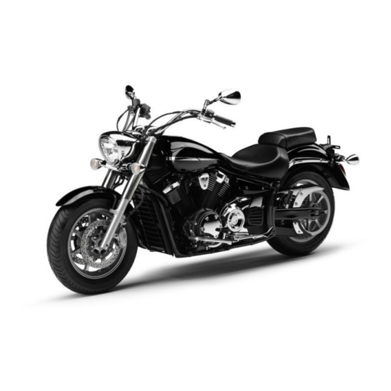
Yamaha midnight star XVS1300A Owner's Manual
Hide thumbs
Also See for midnight star XVS1300A:
- Owner's manual (88 pages) ,
- Owner's manual (90 pages) ,
- Owner's manual (92 pages)

Related Manuals for Yamaha midnight star XVS1300A


Summary of Contents for Yamaha midnight star XVS1300A
- Page 1 Read this manual carefully before operating this vehicle. OWNER’S MANUAL XVS1300A 11C-28199-E3...
- Page 2 Read this manual carefully before operating this vehicle. This manual should stay with this vehicle if it is sold. YAMAHA MOTOR ELECTRONICS CO., LTD. 1450-6, Mori, Mori-machi, Shuchi-gun, Shizuoka-ken, 437-0292 Japan DECLARATION of CONFORMITY Company: YAMAHA MOTOR ELECTRONICS CO., LTD. Address: 1450-6, Mori, Mori-Machi, Shuchi-gun, Shizuoka-Ken, 437-0292 Japan Hereby declare that the product: Kind of equipment: IMMOBILIZER...
- Page 3 EAU10102 Welcome to the Yamaha world of motorcycling! As the owner of the XVS1300A, you are benefiting from Yamaha’s vast experience and newest technology regarding the design and manufacture of high-quality products, which have earned Yamaha a reputation for dependability.
-
Page 4: Important Manual Information
IMPORTANT MANUAL INFORMATION EAU10132 Particularly important information is distinguished in this manual by the following notations: This is the safety alert symbol. It is used to alert you to potential personal injury hazards. Obey all safety messages that follow this symbol to avoid possible injury or death. - Page 5 IMPORTANT MANUAL INFORMATION EAU10200 XVS1300A OWNER’S MANUAL ©2009 by Yamaha Motor Co., Ltd. 1st edition, October 2009 All rights reserved. Any reprinting or unauthorized use without the written permission of Yamaha Motor Co., Ltd. is expressly prohibited. Printed in Japan.
-
Page 6: Table Of Contents
TABLE OF CONTENTS SAFETY INFORMATION ....1-1 FOR YOUR SAFETY – Adjusting the clutch lever free PRE-OPERATION CHECKS ..... 4-1 play ........... 6-16 DESCRIPTION ........2-1 Checking the brake lever free Left view ..........2-1 OPERATION AND IMPORTANT play ........... 6-17 Right view ........2-2 RIDING POINTS......... - Page 7 TABLE OF CONTENTS Replacing a turn signal light bulb ...........6-31 Replacing the license plate light bulb ...........6-31 Replacing the auxiliary light bulb ...........6-32 Supporting the motorcycle ....6-33 Troubleshooting ......6-34 Troubleshooting charts ....6-35 MOTORCYCLE CARE AND STORAGE ..........7-1 Matte color caution ......7-1 Care ..........7-1 Storage ...........7-3 SPECIFICATIONS ......8-1...
-
Page 8: Safety Information
SAFETY INFORMATION EAU10283 Safe Riding • Ride where other motorists can Perform the pre-operation checks each see you. Avoid riding in another time you use the vehicle to make sure it motorist’s blind spot. Be a Responsible Owner is in safe operating condition. Failure to Many accidents involve inexperi- As the vehicle’s owner, you are respon- inspect or maintain the vehicle properly... - Page 9 SAFETY INFORMATION due to excessive speed or under- This motorcycle is designed for on- A passenger should also observe cornering (insufficient lean angle road use only. It is not suitable for the above precautions. for the speed). off-road use. • Always obey the speed limit and Avoid Carbon Monoxide Poisoning never travel faster than warrant- Protective apparel...
- Page 10 Yamaha accessories, which are avail- of the motorcycle is changed. To avoid to minimize imbalance or instabili- able only from a Yamaha dealer, have the possibility of an accident, use ex- been designed, tested, and approved treme caution when adding cargo or Shifting weights can create a sud- by Yamaha for use on your vehicle.
- Page 11 • Accessories fitted to the handle- Use caution when adding electri- genuine Yamaha accessories, recog- bar or the front fork area can cal accessories. If electrical acces- nize that some aftermarket accessories...
-
Page 12: Description
DESCRIPTION EAU10410 Left view 4,5,6,7 1. Front turn signal light (page 6-31) 9. Rear turn signal light (page 6-31) 2. Headlight (page 6-29) 10.Engine oil level check window (page 6-9) 3. Seat lock (page 3-15) 11.Shift pedal (page 3-11) 4. Fuel injection system fuse (page 6-27) 12.Engine oil filler cap (page 6-9) 5. -
Page 13: Right View
DESCRIPTION EAU10420 Right view 10 9 8 1. Tail/brake light (page 6-31) 9. Rear brake light switch (page 6-18) 2. Rear brake fluid reservoir (page 6-19) 10.Engine oil filter cartridge (page 6-9) 3. Owner’s tool kit (page 6-1) 11.Engine oil drain bolt (page 6-9) 4. -
Page 14: Controls And Instruments
DESCRIPTION EAU10430 Controls and instruments 1. Clutch lever (page 3-11) 2. Left handlebar switches (page 3-9) 3. Multi-function meter unit (page 3-6) 4. Main switch/steering lock (page 3-2) 5. Right handlebar switches (page 3-9) 6. Throttle grip (page 6-14) 7. Brake lever (page 3-12) -
Page 15: Instrument And Control Functions
Do not expose any key to exces- a Yamaha dealer to have them re-reg- sively high temperatures. istered. Do not use the key with the red Do not place any key close to bow for driving. -
Page 16: Main Switch/Steering Lock
INSTRUMENT AND CONTROL FUNCTIONS Keep other immobilizer system EAU10472 EAU38530 Main switch/steering lock keys away from the main switch All electrical circuits are supplied with as they may cause signal inter- power; the meter lighting, taillight, li- ference. cense plate light and auxiliary light come on, and the engine can be start- ed. - Page 17 INSTRUMENT AND CONTROL FUNCTIONS EAU10683 To unlock the steering ECA11020 LOCK NOTICE The steering is locked, and all electrical Do not use the parking position for systems are off. The key can be re- an extended length of time, other- moved.
-
Page 18: Indicator And Warning Lights
The oil level warning high beam of the headlight is switched light will flash ten times, then go off for 2.5 seconds. If this occurs, have a Yamaha dealer check the EAU11254 Oil level warning light “ ” vehicle. - Page 19 If this occurs, seconds have passed, the indicator The electrical circuit of the warning light have a Yamaha dealer check the self- light will start flashing indicating the im- can be checked by turning the key to diagnosis system.
-
Page 20: Multi-Function Meter Unit
INSTRUMENT AND CONTROL FUNCTIONS EAU42907 two tripmeters (which show the Speedometer Multi-function meter unit distance traveled since they were last set to zero) a fuel reserve tripmeter (which shows the distance traveled on the fuel reserve) a clock a self-diagnosis device a brightness control mode 1. - Page 21 INSTRUMENT AND CONTROL FUNCTIONS Odometer, tripmeters, fuel reserve Push the “RESET” switch for less tomatically, and the display will return tripmeter and clock than one second to display the to the prior mode after refueling and clock for five seconds, regardless traveling 5 km (3 mi).
- Page 22 If the odometer/tripmeter/clock display release it to start the clock. indicates any error codes, note the code number, and then have a Yamaha If the display indicates error code 52, Self-diagnosis device dealer check the vehicle.
-
Page 23: Anti-Theft Alarm (Optional)
This model can be equipped with an suit the outside lighting conditions. Left optional anti-theft alarm by a Yamaha dealer. Contact a Yamaha dealer for To set the brightness more information. 1. Turn the key to “OFF”. - Page 24 INSTRUMENT AND CONTROL FUNCTIONS Right position. To cancel the turn signal EAU12733 Hazard switch “ ” lights, push the switch in after it has re- With the key in the “ON” or “ ” posi- turned to the center position. tion, use this switch to turn on the haz- ard lights (simultaneous flashing of all EAU12500...
-
Page 25: Clutch Lever
INSTRUMENT AND CONTROL FUNCTIONS EAU42534 EAU12820 EAU12880 “RESET” switch Clutch lever Shift pedal This switch is used to perform selec- tions in the tripmeters, to set the clock and to set the brightness control mode of the multi-function meter unit. See “Multi-function meter unit”... -
Page 26: Brake Lever
INSTRUMENT AND CONTROL FUNCTIONS EAU12890 EAU12941 EAU13091 Brake lever Brake pedal Fuel tank cap 1. Brake lever 1. Brake pedal 1. Fuel tank cap lock cover 2. Unlock. The brake lever is located at the right The brake pedal is on the right side of handlebar grip. -
Page 27: Fuel
INSTRUMENT AND CONTROL FUNCTIONS EAU13221 Fuel The fuel tank cap cannot be closed un- Make sure there is sufficient gasoline in less the key is in the lock. In addition, the tank. the key cannot be removed if the cap is EWA10881 WARNING not properly closed and locked. -
Page 28: Fuel Tank Breather/Overflow Hose
Your Yamaha engine has been de- signed to use regular unleaded gaso- line with a research octane number of 91 or higher. If knocking (or pinging) oc-... -
Page 29: Catalytic Converter
INSTRUMENT AND CONTROL FUNCTIONS EAU13433 ECA10701 EAU42750 Catalytic converter Rider seat NOTICE This model is equipped with a catalytic Use only unleaded gasoline. The use converter in the exhaust system. To remove the rider seat of leaded gasoline will cause unre- 1. -
Page 30: Helmet Holder
INSTRUMENT AND CONTROL FUNCTIONS EAU14322 To release the helmet from the hel- Helmet holder met holder Remove the rider seat, remove the hel- met from the helmet holder, and then install the seat. 1. Projection 2. Seat holder 1. Helmet holder 2. -
Page 31: Adjusting The Shock Absorber Assembly
Do not tamper with or attempt to It is recommended to have a Yamaha open the cylinder assembly. dealer adjust the spring preload. Do not subject the shock ab- 1. -
Page 32: Sidestand
INSTRUMENT AND CONTROL FUNCTIONS EAU15303 below and have a Yamaha dealer re- EAU44892 Sidestand Ignition circuit cut-off system pair it if it does not function proper- The sidestand is located on the left side The ignition circuit cut-off system (com- of the frame. - Page 33 INSTRUMENT AND CONTROL FUNCTIONS WARNING With the engine turned off: 1. Move the sidestand down. If a malfunction is noted, have a Yamaha 2. Make sure that the engine stop switch is set to “ ”. dealer check the system before riding.
-
Page 34: For Your Safety - Pre-Operation Checks
• If necessary, add recommended coolant to specified level. 6-12 • Check cooling system for leakage. • Check operation. • If soft or spongy, have Yamaha dealer bleed hydraulic system. • Check brake pads for wear. Front brake • Replace if necessary. - Page 35 • Make sure that operation is smooth. • Check cable free play. Throttle grip 6-14, 6-21 • If necessary, have Yamaha dealer adjust cable free play and lubricate cable and grip housing. • Make sure that operation is smooth. Control cables 6-21 •...
- Page 36 FOR YOUR SAFETY – PRE-OPERATION CHECKS ITEM CHECKS PAGE • Check operation of ignition circuit cut-off system. Sidestand switch 3-18 • If system is not working correctly, have Yamaha dealer check vehicle.
-
Page 37: Operation And Important Riding Points
Yamaha dealer. The transmission is in the neutral gine in case of a turnover. In this position. -
Page 38: Shifting
(See page 5-2.) The quate lubrication may damage neutral indicator light should come the transmission. 1. Shift pedal on. If not, ask a Yamaha dealer to 2. Neutral position Always use the clutch while check the electrical circuit. changing gears to avoid damag- Shifting gears lets you control the 3. -
Page 39: Tips For Reducing Fuel Consumption
Since the engine is brand new, do not gine speeds during acceleration. immediately have a Yamaha dealer put an excessive load on it for the first Do not rev the engine while shifting check the vehicle. -
Page 40: Parking
OPERATION AND IMPORTANT RIDING POINTS EAU17213 Parking When parking, stop the engine, and then remove the key from the main switch. EWA10311 WARNING Since the engine and exhaust system can become very hot, park in a place where pedestri- ans or children are not likely to touch them and be burned. -
Page 41: Periodic Maintenance And Adjustment
If If you do not have the tools or experi- you are not familiar with vehicle ser- ence required for a particular job, have vice, have a Yamaha dealer perform a Yamaha dealer perform it for you. service. -
Page 42: Periodic Maintenance Chart For The Emission Control System
From 50000 km (30000 mi), repeat the maintenance intervals starting from 10000 km (6000 mi). Items marked with an asterisk should be performed by a Yamaha dealer as they require special tools, data and technical skills. -
Page 43: General Maintenance And Lubrication Chart
PERIODIC MAINTENANCE AND ADJUSTMENT EAU1770C General maintenance and lubrication chart ODOMETER READING ANNUAL ITEM CHECK OR MAINTENANCE JOB 1000 km 10000 km 20000 km 30000 km 40000 km CHECK (600 mi) (6000 mi) (12000 mi) (18000 mi) (24000 mi) √ Air filter element •... - Page 44 PERIODIC MAINTENANCE AND ADJUSTMENT ODOMETER READING ANNUAL ITEM CHECK OR MAINTENANCE JOB 1000 km 10000 km 20000 km 30000 km 40000 km CHECK (600 mi) (6000 mi) (12000 mi) (18000 mi) (24000 mi) • Check belt tension. 10 * Drive belt •...
- Page 45 PERIODIC MAINTENANCE AND ADJUSTMENT ODOMETER READING ANNUAL ITEM CHECK OR MAINTENANCE JOB 1000 km 10000 km 20000 km 30000 km 40000 km CHECK (600 mi) (6000 mi) (12000 mi) (18000 mi) (24000 mi) √ √ √ √ Rear suspension re- •...
- Page 46 PERIODIC MAINTENANCE AND ADJUSTMENT EAU18680 Air filter • This model’s air filter is equipped with a disposable oil-coated paper element, which must not be cleaned with com- pressed air to avoid damaging it. • The air filter element needs to be replaced more frequently when riding in unusually wet or dusty areas. Hydraulic brake service •...
-
Page 47: Removing And Installing The Panel
PERIODIC MAINTENANCE AND ADJUSTMENT EAU18751 EAU42431 Removing and installing the Checking the spark plugs panel The spark plugs are important engine components, which are easy to check. The panel shown needs to be removed Since heat and deposits will cause any to perform some of the maintenance spark plug to slowly erode, the spark jobs described in this chapter. - Page 48 0.8–0.9 mm (0.031–0.035 in) diagnose such problems yourself. In- ed in the additional tool kit, which stead, have a Yamaha dealer check was handed out separately at the To install a spark plug the vehicle.
-
Page 49: Engine Oil And Oil Filter Cartridge
PERIODIC MAINTENANCE AND ADJUSTMENT EAU42597 Engine oil and oil filter car- If a torque wrench is not available when tridge installing a spark plug, a good estimate The engine oil level should be checked of the correct torque is 1/4–1/2 turn before each ride. - Page 50 Make sure that the O-ring is properly An oil filter wrench is available at a seated. 1. Engine oil drain bolt Yamaha dealer. 2. Gasket 7. Install the new oil filter cartridge 6. Apply a thin coat of clean engine...
- Page 51 8. Install the engine oil drain bolt and In order to prevent clutch slip- off and have a Yamaha dealer check its new gasket, and then tighten page (since the engine oil also the vehicle.
-
Page 52: Coolant
If water has been specified in the periodic maintenance added to the coolant, have a and lubrication chart. Yamaha dealer check the anti- freeze content of the coolant as EAU42632 soon as possible, otherwise the To check the coolant level effectiveness of the coolant will 1. -
Page 53: Replacing The Air Filter Element
Have a 4. Install the air filter case cover by in- 2. Pull the air filter element out. Yamaha dealer change the coolant. stalling the bolts. WARNING! Never attempt to remove the radiator cap when the engine is hot. -
Page 54: Checking The Throttle Cable Free Play
To prevent this cle, note the following points regarding from occurring, the valve clearance the specified tires. must be adjusted by a Yamaha dealer at the intervals specified in the periodic Tire air pressure maintenance and lubrication chart. -
Page 55: Tire Inspection
2. Tire tread depth ed below have been approved for this * Total weight of rider, passenger, car- model by Yamaha Motor Co., Ltd. The tires must be checked before each go and accessories ride. If the center tread depth reaches... -
Page 56: Cast Wheels
If any damage is The replacement of all wheel found, have a Yamaha dealer re- and brake related parts, includ- place the wheel. Do not attempt ing the tires, should be left to a... -
Page 57: Checking The Brake Lever Free Play
1. No brake lever free play There should be no free play at the brake lever end. If there is free play, have a Yamaha dealer inspect the brake system. EWA14211 WARNING A soft or spongy feeling in the brake lever can indicate the presence of air in the hydraulic system. -
Page 58: Brake Light Switches
1. Brake pad wear indicator groove by a Yamaha dealer. Each front brake pad is provided with Turn the rear brake light switch adjust- wear indicator grooves, which allow... -
Page 59: Checking The Brake Fluid Level
EAU22580 Before riding, check that the brake fluid Checking the brake fluid level peared, have a Yamaha dealer replace is above the minimum level mark and the brake pads as a set. replenish if necessary. A low brake fluid... -
Page 60: Changing The Brake Fluid
EAU23040 Changing the brake fluid Drive belt slack ter the brake fluid reservoir when Have a Yamaha dealer change the The drive belt slack should be checked refilling. Water will significantly brake fluid at the intervals specified in and adjusted at the intervals specified... -
Page 61: Checking And Lubricating The Cables
A belt tension gauge is available at a bles and cable ends should be lubricat- Yamaha dealer at the intervals speci- Yamaha dealer. ed if necessary. If a cable is damaged fied in the periodic maintenance chart. -
Page 62: Checking And Lubricating The Brake And Shift Pedals
PERIODIC MAINTENANCE AND ADJUSTMENT EAU44272 EAU23142 Recommended lubricant: Checking and lubricating the Checking and lubricating the Lithium-soap-based grease brake and shift pedals brake and clutch levers Brake pedal Brake lever Shift pedal Clutch lever The operation of the brake and shift The operation of the brake and clutch pedals should be checked before each levers should be checked before each... -
Page 63: Checking And Lubricating The Sidestand
The operation of the sidestand should The swingarm pivots must be lubricat- be checked before each ride, and the ed by a Yamaha dealer at the intervals sidestand pivot and metal-to-metal specified in the periodic maintenance contact surfaces should be lubricated if and lubrication chart. -
Page 64: Lubricating The Rear Suspension
The pivoting points of the rear suspen- face and hold it in an upright posi- fork does not operate smoothly, sion must be lubricated by a Yamaha tion. WARNING! To avoid injury, have a Yamaha dealer check or re- dealer at the intervals specified in the securely support the vehicle so pair it. -
Page 65: Checking The Steering
Yamaha dealer check ward and backward. If any free of contact, administer the fol- the wheel bearings. play can be felt, have a Yamaha lowing FIRST AID. dealer check or repair the steering. • EXTERNAL: Flush with plenty of water. - Page 66 To charge the battery cell seals, as this would permanent- er’s tool kit tray together with the Have a Yamaha dealer charge the bat- ly damage the battery. owner’s tool kit by pulling it up- tery as soon as possible if it seems to ward.
-
Page 67: Replacing The Fuses
Replacing the fuses NOTICE stant-voltage battery charger, have a The main fuse, the fuel injection system Yamaha dealer charge your battery. Always keep the battery charged. fuse, and the fuse box, which contains Storing a discharged battery can the fuses for the individual circuits, are cause permanent battery damage. - Page 68 PERIODIC MAINTENANCE AND ADJUSTMENT avoid causing extensive dam- age to the electrical system and possibly a fire. [EWA15131] To access the fuel injection system fuse, remove the starter relay cover by pulling it upward. 1. Starter relay cover 1. Signaling system fuse 2.
-
Page 69: Replacing The Headlight Bulb
5. If the fuse immediately blows cohol or thinner. again, have a Yamaha dealer Headlight lens check the electrical system. Do not affix any type of tinted 6. Install the battery cover, and then film or stickers to the headlight 1. - Page 70 PERIODIC MAINTENANCE AND ADJUSTMENT 1. Bolt 1. Headlight bulb holder 9. Have a Yamaha dealer adjust the 2. Headlight bulb headlight beam if necessary. 3. Disconnect the headlight coupler, 5. Place a new headlight bulb into po- and then remove the bulb cover.
-
Page 71: Replacing The Tail/Brake Light Bulb
PERIODIC MAINTENANCE AND ADJUSTMENT EAU24133 EAU24212 EAU42484 Replacing the tail/brake light Replacing a turn signal light Replacing the license plate bulb bulb light bulb 1. Remove the tail/brake light lens by 1. Remove the turn signal lens by re- 1. Remove the license plate light cov- removing the screws. -
Page 72: Replacing The Auxiliary Light Bulb
PERIODIC MAINTENANCE AND ADJUSTMENT 3. Remove the license plate light 6. Install the socket (together with the EAU42872 Replacing the auxiliary light socket (together with the bulb) by bulb) by pushing it in and turning it bulb turning it counterclockwise, and clockwise until it stops. -
Page 73: Supporting The Motorcycle
PERIODIC MAINTENANCE AND ADJUSTMENT EAU24350 a jack either under each side of the Supporting the motorcycle frame in front of the rear wheel or under Since this model is not equipped with a each side of the swingarm. centerstand, follow these precautions when removing the front and rear wheel or performing other maintenance requiring the motorcycle to stand up-... -
Page 74: Troubleshooting
The following troubleshooting charts represent quick and easy procedures for checking these vital systems your- self. However, should your motorcycle require any repair, take it to a Yamaha dealer, whose skilled technicians have the necessary tools, experience, and know-how to service the motorcycle properly. -
Page 75: Troubleshooting Charts
Remove the spark plugs and check the electrodes. The engine does not start. Have a Yamaha dealer check the vehicle. Check the battery. 4. Battery The engine turns over The battery is good. - Page 76 Start the engine. If the engine overheats again, have a The coolant level Yamaha dealer check and repair the cooling system. is OK. If coolant is not available, tap water can be temporarily used instead, provided that it is changed to the recommended coolant as soon as possible.
-
Page 77: Motorcycle Care And Storage
Rust and corrosion can develop matte colored finished parts. Be Cleaning even if high-quality components are sure to consult a Yamaha dealer for ECA10772 advice on what products to use be- used. A rusty exhaust pipe may go un- NOTICE fore cleaning the vehicle. - Page 78 MOTORCYCLE CARE AND STORAGE off any detergent residue using Test the product on a small hid- plenty of water, as it is harmful den part of the windshield to Salt sprayed on roads in the winter may to plastic parts. make sure that it does not leave remain well into spring.
-
Page 79: Storage
WARNING cals are stored. Contaminants on the brakes or tires can cause loss of control. Consult a Yamaha dealer for ad- Long-term Make sure that there is no oil or vice on what products to use. Before storing your motorcycle for sev- wax on the brakes or tires. - Page 80 MOTORCYCLE CARE AND STORAGE 3. Perform the following steps to pro- 4. Lubricate all control cables and the tect the cylinders, piston rings, etc. pivoting points of all levers and from corrosion. pedals as well as of the side- a. Remove the spark plug caps stand/centerstand.
-
Page 81: Specifications
SPECIFICATIONS Dimensions: Engine oil: Fuel: Overall length: Recommended brand: Recommended fuel: 2490 mm (98.0 in) YAMALUBE Regular unleaded gasoline only Overall width: Type: Fuel tank capacity: 1000 mm (39.4 in) SAE 10W-30, 10W-40, 10W-50, 15W-40, 19.0 L (5.02 US gal, 4.18 Imp.gal) Overall height: 20W-40 or 20W-50 Fuel reserve amount:... - Page 82 SPECIFICATIONS Gear ratio: Manufacturer/model: Operation: 1st: BRIDGESTONE/EXEDRA G722 G Right hand operation 36/13 (2.769) Loading: Recommended fluid: 2nd: DOT 4 Maximum load: 32/18 (1.778) Rear brake: 209 kg (461 lb) 3rd: (Total weight of rider, passenger, cargo and Type: 29/21 (1.381) accessories) Single disc brake 4th:...
- Page 83 SPECIFICATIONS Voltage, capacity: Immobilizer system indicator light: 12 V, 18.0 Ah Headlight: Fuses: Bulb type: Main fuse: Halogen bulb 50.0 A Bulb voltage, wattage × quantity: Headlight fuse: 20.0 A Headlight: 12 V, 60 W/55 W × 1 Signaling system fuse: 10.0 A Tail/brake light: 12 V, 5.0 W/21.0 W ×...
-
Page 84: Consumer Information
Record the vehicle identification num- ber and model label information in the spaces provided below for assistance when ordering spare parts from a Yamaha dealer or for reference in case the vehicle is stolen. VEHICLE IDENTIFICATION NUMBER: 1. Vehicle identification number 1. - Page 85 INDEX Front fork, checking.......6-24 Fuel ............3-13 Air filter element, replacing ....6-13 Panel, removing and installing....6-7 Fuel consumption, tips for reducing ..5-3 Anti-theft alarm (optional) ....... 3-9 Parking............ 5-4 Fuel level warning light......3-4 Auxiliary light bulb, replacing ....6-32 Part locations ..........
- Page 86 INDEX Turn signal indicator light ......3-4 Turn signal light bulb, replacing .... 6-31 Turn signal switch ......... 3-10 Valve clearance ........6-14 Vehicle identification number ....9-1 Wheel bearings, checking..... 6-25 Wheels ..........6-16...
- Page 88 YAMAHA MOTOR CO., LTD. PRINTED ON RECYCLED PAPER PRINTED IN JAPAN 2009.11-0.3×1 CR...