Advertisement
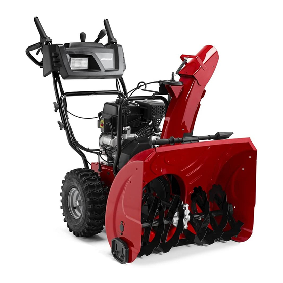
ST 2368 EP
Operator's Manual
Always Wear Eye Protection During Operation
Gasoline containing up to 10% ethanol (E10) is acceptable for use in this machine.
The use of any gasoline exceeding 10% ethanol (E10) will void the product warranty.
115 73 45-27 Rev. 3
WARNING:
Read this Man u al and follow all Warnings
and Safety Instructions. Fail ure to do so
can re sult in serious in ju ry.
Advertisement
Table of Contents

Related Manuals for Jonsered ST 2368 EP


Summary of Contents for Jonsered ST 2368 EP
- Page 1 ST 2368 EP Operator's Manual WARNING: Read this Man u al and follow all Warnings and Safety Instructions. Fail ure to do so can re sult in serious in ju ry. Always Wear Eye Protection During Operation Gasoline containing up to 10% ethanol (E10) is acceptable for use in this machine.
-
Page 2: Safety Rules
IMPORTANT Safe Operation Practices for Walk-Behind Snow Throwers This snow thrower is capable of amputating hands and feet and throwing objects. Failure to observe the following safety instructions could result in serious injury. WARNING: Snow throwers have ex- Look for this symbol to point out im- posed rotating parts, which can cause por tant safety precautions. -
Page 3: Table Of Contents
6. When cleaning, repairing or inspecting the snow 16. Never touch a hot engine or muffler. thrower, stop the engine and make certain the collector/ impeller and all moving parts have stopped. Disconnect Clearing a Clogged Discharge Chute the spark plug wire and keep the wire away from the Hand contact with the rotating impeller inside the discharge plug to prevent someone from accidentally starting the chute is the most common cause of injury associated with... - Page 4 PARTS PACKED SEPARATELY IN CARTON (3) KNOB (6) LOCKNUTS (6) SHEAR BOLTS 1/4-20 x 1-3/4 1/4-20 (1) MULTI- WRENCH SAFTEY IGNITION KEY (S) (2) CARRIAGE BOLTS 5/16-18 x 2 1/4” (1) SPRING (1) LOCKNUT (1) CARRIAGE BOLT 5/16-18 5/16-18 x 5/8 (1) LOCKNUT (1) NYLON (1) SHOULDER...
-
Page 5: Assembly / Pre-Operation
ASSEMBLY / PRE-OPERATION Read these instructions and this manual in its entirety before you attempt to assemble or operate your new snow thrower. Reading the entire manual will familiarize you with the unit, which will assist you in assembly, operation and maintenance of the product. - Page 6 ASSEMBLY / PRE-OPERATION INSTALL DISCHARGE CHUTE / CHUTE ROTATOR HEAD INSTALL CHUTE DEFLECTOR REMOTE CONTROL (See Fig. 4 and 5) (See Figs. 6 and 7) 1. Install remote cable bracket to discharge chute with NOTE: The multi-wrench provided in your parts bag may 5/16-18 carriage bolt and 5/16-18 locknut as shown.
-
Page 7: Operation
OPERATION KNOW YOUR SNOW THROWER READ THIS OWNER'S MANUAL AND ALL SAFETY RULES BEFORE OPERATING YOUR SNOW THROWER. Compare the illustrations with your snow thrower to familiarize yourself with the location of various controls and adjustments. Save this manual for future reference. These symbols may appear on your snow thrower or in literature supplied with the product. - Page 8 OPERATION DISCHARGE CHUTE CONTROL LEVER AUGER CHOKE MUF FLER CONTROL POWER CORD CON TROL DRIVE SPEED LEVER PLUG GAS O LINE CON TROL LEVER FILLER CAP THROTTLE / ENGINE ELECTRIC DEFLECTOR CONTROL START REMOTE BUTTON CONTROL ON / OFF LEVER SWITCH LIGHT TRACTION...
- Page 9 OPERATION The operation of any snow thrower can result TO USE THROTTLE CONTROL (See Fig. 11) in foreign objects thrown into the eyes, which The throttle control is located on the engine. Always op er ate can result in severe eye damage. Always wear the snow thrower with the engine at full throttle.
- Page 10 OPERATION TO THROW SNOW (See Fig. 13) TO MOVE FORWARD AND BACKWARD (See Fig. 15) The auger rotation is controlled by the auger control lever SELF-PROPELLING, forward and reverse movement of located on the right side handle. the snow thrower, is controlled by the traction drive control lever located on the left side handle.
-
Page 11: Before Starting The Engine
OPERATION TO ADJUST SKID PLATES (See Fig. 17) BEFORE STARTING THE ENGINE NOTE: The wrench provided in your parts bag may be CHECK ENGINE OIL LEVEL (See Fig. 18) used to adjust the skid plates. The engine on your snow thrower has been shipped from Skid plates are located on each side of the auger housing the factory already filled with oil. - Page 12 OPERATION TO START ENGINE 6. Pull recoil starter handle quickly. Do not allow starter rope to snap back. • Ensure fuel shut-off valve is in the “OPEN” position. Your snow thrower engine is equipped with both a 120 Volt 7. When the engine starts, release the recoil starter han dle A.C.
-
Page 13: Maintenance Schedule
MAINTENANCE LUBRICATION CHART GENERAL REC OM MEN DA TIONS ➀ The warranty on this snow thrower does not cover items SAE 5W30 Motor Oil that have been sub ject ed to operator abuse or negligence. ➁ See “Engine” in Maintenance section To receive full value from the warranty, operator must ➂... - Page 14 MAINTENANCE SNOW THROWER Check the crankcase oil level before starting the engine and after each five (5) hours of continuous use. Tighten oil Always observe the safety rules when performing any fill cap / dipstick securely each time you check the oil level. main te nance.
-
Page 15: Service And Adjustments
SERVICE AND ADJUSTMENTS To replace the shear bolts: WARNING: To avoid serious injury, before 1. Disengage all controls and move throttle control to performing any service or ad just ments: STOP position. Wait for all moving parts to stop. 1. Be sure the on/off switch is in the 2. -
Page 16: Service And Adjustments
SERVICE AND ADJUSTMENTS TO REPLACE BELTS AUGER BELT REPLACEMENT (See Fig. 22) TO REMOVE AUGER BELT The auger and traction drive belts are not adjustable. If the belts are damaged or begin to slip from wear, they should 1. Remove upper 5/16" bolts and lower 1/4" bolts from be replaced. - Page 17 SERVICE AND ADJUSTMENTS DRIVE BELT REPLACEMENT (See Fig. 23) AFTER REPLACING BELT(S) TO REMOVE DRIVE BELT 1. INSTALL BELT COVER and two (2) screws. Tighten securely. 1. Remove auger belt. See “TO REMOVE AUGER BELT” in this section. 2. INSTALL DISCHARGE CHUTE – See “INSTALL DISCHARGE CHUTE / CHUTE ROTATER HEAD”...
-
Page 18: Service And Ad Just Ments
SERVICE AND ADJUSTMENTS TO ADJUST CHUTE ROTATOR CABLE TENSION AUGER PERFORMANCE AND CABLE ADJUSTMENT (See Fig. 25) (See Fig. 25) 1. Adjust cable tension by loosening the jam nuts next to NOTE: If you do not feel comfortable making this adjustment the turn buckle. -
Page 19: Storage
STORAGE Immediately prepare your snow thrower for storage at • Empty the fuel tank by starting the engine and letting it run until the fuel lines and car bu re tor are empty. the end of the season or if the unit will not be used for 30 days or more. -
Page 20: Troubleshooting
TROUBLESHOOTING See appropriate section in manual unless directed to a service center/department. PROBLEM CAUSE CORRECTION Does not start 1. Fuel shut-off valve (if so equipped) 1. Turn fuel shut-off valve to OPEN position. in OFF position. 2. Safety ignition key is not inserted. 2. - Page 21 SERVICE NOTES...
- Page 22 SERVICE NOTES...
- Page 23 SERVICE NOTES...
- Page 24 04.13.16 TH/BY Printed in U.S.A.