ZALMAN CNPS9900 Max User Manual
Intel socket lga 2011 v3/2011/ 1366 / 1156 / 1155 / 1151 / 1150 / 775 cpus
amd socket fm2 / fm1 / am3+ / am3 / am2+ / am2 cpu&apus
Hide thumbs
Also See for CNPS9900 Max:
- User manual (12 pages) ,
- User manual (9 pages) ,
- User manual (9 pages)
Advertisement
Quick Links
User's Manual
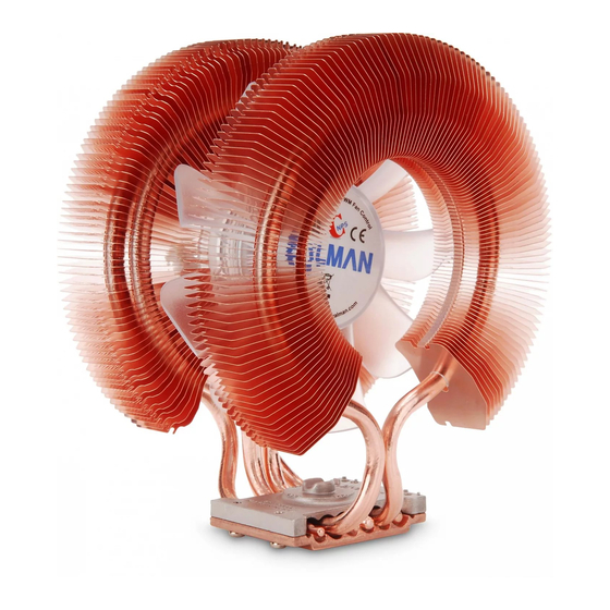
CNPS9900 Series
CNPS9900 Max
Intel Socket LGA 2011 V3/2011/ 1366 / 1156 / 1155 / 1151 / 1150 / 775 CPUs
AMD Socket FM2 / FM1 / AM3+ / AM3 / AM2+ / AM2 CPU&APUs
CNPS9900A LED / NT
Intel Socket LGA 1366 / 1156 / 1155 / 1151 / 1150 / 775 CPUs
AMD Socket FM2 / FM1 / AM3+ / AM3 / AM2+ / AM2 CPU&APUs
To ensure safe and easy installation, please read
the following precautions
www.ZALMAN.com
Ver. 150806
Advertisement

Related Manuals for ZALMAN CNPS9900 Max


Summary of Contents for ZALMAN CNPS9900 Max
- Page 1 User’s Manual CNPS9900 Series CNPS9900 Max Intel Socket LGA 2011 V3/2011/ 1366 / 1156 / 1155 / 1151 / 1150 / 775 CPUs AMD Socket FM2 / FM1 / AM3+ / AM3 / AM2+ / AM2 CPU&APUs CNPS9900A LED / NT Intel Socket LGA 1366 / 1156 / 1155 / 1151 / 1150 / 775 CPUs AMD Socket FM2 / FM1 / AM3+ / AM3 / AM2+ / AM2 CPU&APUs...
-
Page 2: Specifications
Check the components list and condition of the product before installation. If any problem is found, contact the retailer to obtain a replacement. Zalman Tech Co., Ltd. is not responsible for any damages due to overclocking. Before transportation of the system, the cooler must be removed. -
Page 3: Common Components
(Socket LGA 2011 V3/ (Socket LGA 1156/1155/ 2011 CNPS9900MAX Only) 1151/1150/775/AMD) Nuts Double-sided Tape Loading Block 2) Intel Components 3) AMD Components CNPS9900 MAX : 2011 V3/2011/1366/1156 Socket FM2/FM1/AM3+/AM3/AM2+/AM2 /1155/1151/1150/775 CNPS9900A LED / NT : 1366/1156/1155/1151/1150/775 AMD Clip Intel Clip .COM... -
Page 4: Installation Requirements
4. Installation Requirements 1) Space Requirements The installation requires unobstructed space of 133mm (width) x 96mm (length) x 154mm (height) with the CPU as the central reference point. Before installation, please check if memory modules or motherboard heatsinks will not have any clearance issues with the CPU cooler. -
Page 5: Installation
Clip installation. Insert 1) Intel Socket 2011 V3 / 2011 Installation (CNPS9900 MAX Series Only) Apply thermal grease just enough to thinly cover the CPU surface. Then, insert four Silver Bolts (type A) through the outermost Intel Clip holes, and using the 3/32” Allen Wrench, fasten the Silver Bolts incrementally while alternating between them. - Page 6 2) Intel Socket LGA 1366/1156/1155/1151/1150/775 Installation ① Insert the Nuts to the Backplate according to the socket type and secure them with Side Caps. Socket 775 Socket 1156/1155/1151/1150 Socket 1366 Caution Take note of the orientation of the Nuts and the Side Caps. ②...
- Page 7 ③ Socket LGA775 Installation Peel off the Loading Block cover and attach it to the Backplate with the sticky side facing the center of the Backplate. Loading Block Peel off one side of the Double-sided Tape and attach it with the sticky side facing the Loading block.
- Page 8 ④ Attach the Backplate assembly to the back side of the motherboard by aligning the Nuts to the motherboard mountingholes. If you were unsuccessful at first attempt, you may continue with the installation without the Double-sided Tape as it is not a necessary component.
- Page 9 B. AMD Socket Installation 1) AMD Socket FM2/ FM1/AM3+/AM3/AM2+/AM2 Installation ① Partially unscrew the four bolts located on the base of the CPU cooler. Then, insert the AMD Clips between the base and the heatpipe cover, with the clips bent away from the heatsink. Base AMD Clip Heatpipe cover...
- Page 10 ③ Peel off the Loading Block cover and attach it to the Backplate with the sticky side facing the center of the Backplate. Loading Block Peel off one side of the Double-sided Tape and attach it with the sticky side facing the Loading block. Then, peel off the top cover. Double-sided Tape Caution Please note that the sticky side of the Loading Block serves to attach the Loading Block to...
- Page 11 ⑤ Attach the Backplate assembly to the back side of the motherboard by aligning the Nuts to the motherboard mounting holes. If you were unsuccessful at first attempt, you may continue with the installation without the Double-sided Tape as it is not a necessary component.