Table of Contents
Advertisement
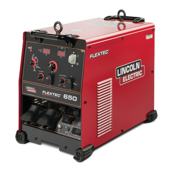
Operator's Manual
FLEXTEC
Register your machine:
www.lincolnelectric.com/register
Authorized Service and Distributor Locator:
www.lincolnelectric.com/locator
Save for future reference
Date Purchased
Code: (ex: 10859)
Serial: (ex: U1060512345)
IM10217
| Issue D ate June-15
© Lincoln Global, Inc. All Rights Reserved.
TM
650
For use with machines having Code Numbers:
12391
Advertisement
Table of Contents

Related Manuals for Lincoln Electric FLEXTECTM 650


Summary of Contents for Lincoln Electric FLEXTECTM 650
- Page 1 Operator’s Manual FLEXTEC For use with machines having Code Numbers: 12391 Register your machine: www.lincolnelectric.com/register Authorized Service and Distributor Locator: www.lincolnelectric.com/locator Save for future reference Date Purchased Code: (ex: 10859) Serial: (ex: U1060512345) IM10217 | Issue D ate June-15 © Lincoln Global, Inc. All Rights Reserved.
- Page 2 THANK YOU FOR SELECTING A QUALITY PRODUCT BY KEEP YOUR HEAD OUT OF THE FUMES. DON’T get too close to the arc. LINCOLN ELEC TRIC. Use corrective lenses if necessary to stay a reasonable distance away from the arc. READ and obey the Safety Data PLEASE EXAMINE CARTON AND EQUIPMENT FOR Sheet (SDS) and the warning label DAMAGE IMMEDIATELY...
- Page 3 MAGNETIC FIELDS MAY W117.2-1974. A Free copy of “Arc Welding Safety” booklet BE DANGEROUS E205 is available from the Lincoln Electric Company, 22801 St. Clair Avenue, Cleveland, Ohio 44117-1199. 2.a. Electric current flowing through any conductor BE SURE THAT ALL INSTALLATION, OPERATION, causes localized Electric and Magnetic Fields (EMF).
-
Page 4: Electric Shock Can Kill
S FETY ELECTRIC SHOCK ARC RAYS CAN BURN. CAN KILL. 3.a. The electrode and work (or ground) circuits are 4.a. Use a shield with the proper filter and cover plates to protect your electrically “hot” when the welder is on. Do eyes from sparks and the rays of the arc when welding or not touch these “hot”... - Page 5 S FETY WELDING AND CUTTING CYLINDER MAY EXPLODE IF SPARKS CAN CAUSE DAMAGED. FIRE OR EXPLOSION. 7.a. Use only compressed gas cylinders containing the correct shielding gas for the process used 6.a. Remove fire hazards from the welding area. If and properly operating regulators designed for this is not possible, cover them to prevent the welding sparks the gas and pressure used.
-
Page 6: Table Of Contents
FLEXTEC TABLE OF CONTENTS Page Installation .......................Section A Technical Specifications ..................A-1 Welding Process, Physical Dimensions ..............A-2 Safety Precautions ....................A-3 VRD™ (Voltage Reduction Device) ................A-3 Select Suitable Location..................A-3 Lifting.......................A-3 Stacking ......................A-3 Environmental Limitations ................A-3 Input and Grounding Connections ..............A-3 High Frequency Protection................A-3 High Temperature Operation.................A-3 Input Connection ....................A-4 Input Fuse and Supply Wire Considerations ............A-4... - Page 7 FLEXTEC NOTES...
-
Page 8: Installation
FLEXTEC INSTALLATION TECHNICAL SPECIFICATIONS - FLEXTEC™ 650 POWER SOURCE-INPUT VOLTAGE AND CURRENT Input Amperes Model Duty Cycle Input Voltage ± 10% Power Factor @ Idle Power Rated Output 60% rating 61 / 50 / 40 230 MAX.( Fan On) K3060-3 380 / 460 / 575 / 3 / 50 / 60 100% rating 57 / 47 / 38... - Page 9 FLEXTEC INSTALLATION WELDING PROCESS PROCESS OUTPUT RANGE (AMPERES) OCV (U OCV (U GMAW (CV) 40-815 10-815 GTAW (CC) SMAW (CC) 15-815 FCAW-GS (CV) 40-815 FCAW-SS (CV) 40-815 SAW (CV) 40-815 PHYSICAL DIMENSIONS MODEL HEIGHT WIDTH DEPTH WEIGHT K3060-3 29.33 in (745 mm) 165lbs (74.8kg)* 21.8 in (554 mm) 16.14 in (410 mm)
-
Page 10: Safety Precautions
FLEXTEC INSTALLATION SAFETY PRECAUTIONS TILTING Place the machine directly on a secure, level surface or WARNING on a recommended undercarriage. The machine may topple over if this procedure is not followed. ELECTRIC SHOCK can kill. LIFTING ONLY QUALIFIED PERSONNEL The FLEXTEC™ 650 has 2 lifting eyelets and 2 han- SHOULD PERFORM THIS INSTALLA- dles that can be used to lift the machine. -
Page 11: High Temperature Operation
FLEXTEC INSTALLATION HIGH TEMPERATURE OPERATION INPUT FUSE AND SUPPLY WIRE CONSIDERATIONS WELDER OUTPUT RATINGS AT 55°C ELEVATED TEMPERATURES Refer to Specification in this Installation Section for recommended fuse, wire sizes and type of the copper AMPS DUTY CYCLE VOLTS TEMPERATURES wires. -
Page 12: Cable Connections
FLEXTEC INSTALLATION CABLE CONNECTIONS See FIGURE A.2 for locating 6-pin and 14-pin con- nectors on the front of the FLEXTEC™ 650. 6-PIN REMOTE CONTROL CONNECTOR Function Wiring 6-pin remote 77 Remote potentiometer, 10K control con- 76 Remote potentiometer, wiper nector for 75 Remote potentiometer, common remote or Trigger, common... -
Page 13: Recommended Electrode And Work Cable For Arc Welding
FLEXTEC INSTALLATION RECOMMENDED ELECTRODE AND The following recommendations apply to all output polarities and weld modes: WORK CABLE SIZES FOR ARC WELDING • Select the appropriate size cables per the General Guidelines “Output Cable Guidelines” (See Table A.1). Connect the electrode and work cables between the Excessive voltage drops caused by undersized appropriate output studs of the FLEXTEC™... -
Page 14: Control Cable Connections, Paralleling
FLEXTEC INSTALLATION Regarding cable placement, best results will be CONTROL CABLE CONNECTIONS obtained when control cables are routed separate from the weld cables. This minimizes the possibility of General Guidelines interference between the high currents flowing Genuine Lincoln control cables should be used at all through the weld cables, and the low level signals in times (except where noted otherwise). - Page 15 FLEXTEC INSTALLATION CONNECTING LF-72 AND LF-74 TO THE FLEXTEC ™ CONTROL SETTING WELD MODE CV, CV-INNERSHIELD WELD TERMINALS LOCAL REMOTE/LOCAL (REMOTE IF K2329-1 INSTALLED) VOLTMETER POLARITY PROCESS DEPENDENT...
- Page 16 FLEXTEC INSTALLATION CONNECTING LN-10 AND DH-10 TO THE FLEXTEC ™ CONTROL SETTING WELD MODE CV, CV-INNERSHIELD WELD TERMINALS REMOTE/LOCAL REMOTE VOLTMETER POLARITY PROCESS DEPENDENT LN-10,DH-10 CONTROL SWITCH Setting the DIP Switches SETUP The DIP switches are each labeled with an “ON” arrow showing the on direction for each of the 8 indi- Initial set up of the LN-10, DH-10 control for the sys- vidual switches in each DIP switch (S1 and S2).
- Page 17 FLEXTEC INSTALLATION CONNECTING LN-25 PRO, LN-25 PIPE, ACTIVE8 TO THE FLEXTEC ™ CONTROL SETTING WELD MODE CV, CV-INNERSHIELD WELD TERMINALS REMOTE/LOCAL LOCAL VOLTMETER POLARITY PROCESS DEPENDENT CONNECTING LN-25 PRO DUAL POWER TO THE FLEXTEC ™ CONTROL SETTING WELD MODE CV, CV-INNERSHIELD WELD TERMINALS REMOTE/LOCAL REMOTE...
- Page 18 FLEXTEC INSTALLATION CONNECTING LN-7 TO THE FLEXTEC ™ CONTROL SETTING WELD MODE CV, CV-INNERSHIELD WELD TERMINALS REMOTE/LOCAL LOCAL VOLTMETER POLARITY PROCESS DEPENDENT CONNECTING LN-8 AND LN-9 TO THE FLEXTEC ™ CONTROL SETTING WELD MODE CV, CV-INNERSHIELD WELD TERMINALS REMOTE/LOCAL REMOTE VOLTMETER POLARITY PROCESS DEPENDENT A-11...
- Page 19 FLEXTEC INSTALLATION CONNECTING NA-3, NA-5 TO THE FLEXTEC ™ CONTROL SETTING WELD MODE CV- SAW WELD TERMINALS REMOTE/LOCAL REMOTE VOLTMETER POLARITY PROCESS DEPENDENT CONNECTING LT-7 TO THE FLEXTEC ™ CONTROL SETTING WELD MODE CV- SAW WELD TERMINALS REMOTE/LOCAL REMOTE VOLTMETER POLARITY PROCESS DEPENDENT A-12...
-
Page 20: Operation
FLEXTEC OPERATION SAFETY PRECAUTIONS GRAPHIC SYMBOLS THAT APPEAR ON THIS MACHINE Read this entire section of operating instructions before operating the machine. OR IN THIS MANUAL WARNING INPUT POWER ELECTRIC SHOCK can kill. • Unless using cold feed feature, when feeding with gun trigger, the electrode and drive mechanism are always electrically energized and... -
Page 21: Product Description
FLEXTEC OPERATION GRAPHIC SYMBOLS THAT The FLEXTEC™ 650 is designed for the North America and export markets and operates on 3 phase APPEAR ON THIS MACHINE 380V, 460V, or 575V 50hz or 60hz power. OR IN THIS MANUAL DUTY CYCLE REDUCED OPEN The FLEXTEC™... -
Page 22: Recommended Processes And Equipment
FLEXTEC OPERATION RECOMMENDED PROCESSES AND EQUIPMENT RECOMMENDED PROCESSES The FLEXTEC™ 650 is designed for CC-SMAW, CC- GTAW (lift tig), CV-GMAW, CV-FCAW-SS, CV- FCAW-GS and CV-SAW welding processes. (arc gouging) is also supported. PROCESS LIMITATIONS The FLEXTEC™ 650 is suitable only for the process- es listed. -
Page 23: Case Front Controls
FLEXTEC OPERATION CASE FRONT CONTROL DESCRIPTIONS 8. Local/Remote Selector Toggle Switch: Sets the control of the output to local (output control (See Figure B.1) knob) or remote (K857 hand amptrol or K870 foot amptrol). 1. Power Switch: Controls input power to the Flextec 650. -
Page 24: Case Back Controls
FLEXTEC OPERATION CASE BACK CONTROLS (See Figure B.2) 1. Input Power Cord Access Hole. 2. Access Panel – Allows access for connecting input power and configuring the machine. 3. Input Power Reconnect – Configures the machine for the input supply voltage. 4. -
Page 25: Internal Controls
FLEXTEC OPERATION INTERNAL CONTROLS - ENABLING VRD To Enter VRD™ Mode (VRD™ Enabled) ™ a. For 380V input: Switch #5 in the “ON” Internal Controls Description Position. The Control PC Board has one bank of Dip Switches. As shipped from the factory VRD™ mode is disabled and the Dip Switches are all in the “off”... -
Page 26: Power-Up Sequence
Many variables beyond the control of The Lincoln Electric Arc Control Dial Company affect the results obtained in applying •... - Page 27 FLEXTEC OPERATION Weld Terminals On/Remote Toggle Switch VRD™ (VOLTAGE REDUCTION DEVICE) • This switch determines the trigger location. INDICATOR LIGHT • When set to the “ON” position, the weld terminals are at OCV (open circuit voltage) and ready to weld. There are 2 indicator lights on the case front of the •...
- Page 28 FLEXTEC OPERATION Output Control Local/Remote – When the control is set to Hot Start - The Hot Start control regulates the starting current “LOCAL” (no remote potentiometer/control plugged into the 6 at arc initiation. Hot Start can be set to “0” and no additional pin or 14 pin connectors), the output is controlled through the current is added at arc start.
- Page 29 FLEXTEC OPERATION Voltage Display Meter – This display will display the pre-set Output Control Local/Remote – When the control is set to “LOCAL” (no remote potentiometer/control plugged into the 6 welding voltage when the machine is in the idle state. After pin or 14 pin connectors), the output is controlled through the welding, the meter holds the actual voltage value for 5 seconds.
-
Page 30: Accessories
FLEXTEC ACCESSORIES TIG Options OPTIONS / ACCESSORIES Pro-Torch™ TIG Torches – PTA- General Options 9, PTA-17, PTA-26 – 2 piece power cord. K2149-1 Work Lead Package. Foot Amptrol® Provides 25 ft. (7.6 m) of remote current control for TIG welding. K1842-10 10ft. -
Page 31: Maintenance
FLEXTEC MAINTENANCE SAFETY PRECAUTIONS PERIODIC MAINTENANCE WARNING Thermal Protection Thermostats protect the machine from excessive ELECTRIC SHOCK can kill. operating temperatures. Excessive temperatures may • Only Qualified personnel should perform this maintenance. be caused by a lack of cooling air or operating the machine beyond the duty cycle and output rating. - Page 32 FLEXTEC NOTES...
-
Page 33: How To Use Troubleshooting Guide
HOW TO USE TROUBLESHOOTING GUIDE WARNING Service and Repair should only be performed by Lincoln Electric Factory Trained Personnel. Unauthorized repairs performed on this equipment may result in danger to the technician and machine operator and will invalidate your factory warranty. For your safety and to avoid Electrical Shock, please observe all safety notes and precautions detailed throughout this manual. - Page 34 COURSE OF ACTION Major physical or electrical damage 1. Contact your local authorized is evident when the sheet metal Lincoln Electric Field Service facil- covers are removed. ity for technical assistance. Machine won’t weld, can’t get any 1. If the displays show an Err ### output.
-
Page 35: Using The Status Led To Troubleshoot System Problems
FLEXTEC TROUBLESHOOTING Observe all Safety Guidelines detailed throughout this manual USING THE STATUS LED TO TROUBLESHOOT SYSTEM PROBLEMS Errors are displayed on the amperage and voltage display meters. In addition, there are status lights on the con- trol pc board and the switch pc board that contain error sequences. Included in this section is information about the fault codes indicated on the status lights and some basic trou- bleshooting charts for both machine and weld performance. -
Page 36: Error Codes
FLEXTEC TROUBLESHOOTING Observe all Safety Guidelines detailed throughout this manual FLEXTEC™ 650 Fault Codes Error Corrective Action Description Possible Cause Code# Input Power Misconnect. Verify the primary reconnect Occurs upon power up when the supply Supply Voltage is too high. is properly configured for the voltage to the switch pcb exceeded accept- able levels. - Page 37 FLEXTEC NOTES...
- Page 38 FLEXTEC DIAGRAMS FRONT OF MACHINE J4-12 J4-11 J4-10 J4-9 J4-8 J4-7 J4-6 J4-5 J4-4 J4-3 J4-2 J4-1 ~42V ~36V ~115V...
- Page 39 FLEXTEC DIAGRAMS...
- Page 40 FLEXTEC NOTES...
- Page 41 FLEXTEC NOTES...
- Page 58 ● Do not touch electrically live parts or ● Keep flammable materials away. ● Wear eye, ear and body protection. WARNING electrode with skin or wet clothing. ● Insulate yourself from work and ground. Spanish ● No toque las partes o los electrodos ●...
- Page 59 ● Keep your head out of fumes. ● Turn power off before servicing. ● Do not operate with panel open or WARNING ● Use ventilation or exhaust to guards off. remove fumes from breathing zone. Spanish ● Los humos fuera de la zona de res- ●...
- Page 60 Lincoln Electric for advice or information about their use of our products. We respond to our customers based on the best information in our possession at that time. Lincoln Electric is not in a position to warrant or guarantee such advice, and assumes no liability, with respect to such information or advice.