Table of Contents
Advertisement
FOR CAR USE ONLY/POUR APPLICATION AUTOMOBILE/PARA USO EN AUTOMÓVILES
• OWNER'S MANUAL
• MODE D'EMPLOI
• MANUAL DE OPERACIÓN
ALPINE ELECTRONICS MARKETING, INC.
1-7, Yukigaya-Otsukamachi, Ota-ku,
Tokyo 145-0067, JAPAN
Phone: 03-5499-4531
ALPINE ELECTRONICS OF AMERICA, INC.
19145 Gramercy Place, Torrance,
California 90501, U.S.A.
Phone 1-800-ALPINE-1 (1-800-257-4631)
ALPINE ELECTRONICS OF AUSTRALIA PTY. LTD.
161-165 Princes Highway, Hallam
Victoria 3803, Australia
Phone 03-8787-1200
ALPINE ELECTRONICS GmbH
Wilhelm-Wagenfeld-Str. 1-3,
80807 München, Germany
Phone 089-32 42 640
JEIL Moon Hwa Co.
18-6, 3Ga, Pil_dong, Jung_gu, Seoul, Korea
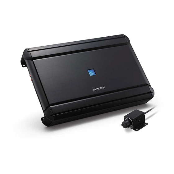
MRV-M1200
MONO POWER AMPLIFIER
Please read before using this equipment.
Veuillez lire avant d'utiliser cet appareil.
Léalo antes de utilizar este equipo.
ALPINE ELECTRONICS OF U.K. LTD.
Alpine House
Fletchamstead Highway, Coventry CV4 9TW, U.K.
www.alpine.co.uk
ALPINE ELECTRONICS France S.A.R.L.
184 allée des Erables
CS 52016 – Villepinte
95 945 Roissy CDG cedex
FRANCE
Phone : + 33(0)1 48 63 89 89
ALPINE ITALIA S.p.A.
Viale Cristoforo Colombo, 8
20090 Trezzano sul Naviglio MI, Italy
Phone +39 02 484781
ALPINE ELECTRONICS DE ESPAÑA, S.A.
Portal de Gamarra 36, Pabellón, 32
01013 Vitoria (Alava)-APDO 133, Spain
Phone 945-283588
Designed by ALPINE Japan
Printed in Korea
68-29530Z91-A (Y-A5)
M3514596010
EN
FR
ES
Advertisement
Table of Contents

Related Manuals for Alpine MRV-M1200


Summary of Contents for Alpine MRV-M1200
- Page 1 CS 52016 – Villepinte Phone 1-800-ALPINE-1 (1-800-257-4631) 95 945 Roissy CDG cedex FRANCE Phone : + 33(0)1 48 63 89 89 ALPINE ELECTRONICS OF AUSTRALIA PTY. LTD. 161-165 Princes Highway, Hallam Victoria 3803, Australia ALPINE ITALIA S.p.A. Phone 03-8787-1200 Viale Cristoforo Colombo, 8...
-
Page 3: Table Of Contents
They contain instructions on how to use this product in a safe and effective manner. DO NOT ALLOW CABLES TO BECOME ENTANGLED IN Alpine cannot be responsible for problems SURROUNDING OBJECTS. resulting from failure to observe the instructions in Arrange wiring and cables in compliance with the manual this manual. -
Page 4: Service Care
IMPORTANT Failure to do so may cause personal injury or damage to the product. Return it to your authorized Alpine dealer or Please record the serial number of your unit in the nearest Alpine Service Center for repairing. -
Page 5: Installation
Self-Tapping Screws (M4 × 12) INSTALLATION Due to the high power output of the MRV-M1200 considerable heat is produced when the amplifier is in operation. For this reason, the amplifier should be mounted in a location which will allow for free circulation of air, such as inside the trunk. -
Page 6: Connections
(+) terminal of the vehicle’s battery with contact them for further information. appropriate in-line vehicle’s fuse (see Battery Lead • Your Alpine dealer knows best about noise section). Do not connect this lead to the vehicle’s prevention measures so consult your dealer for fuse block. - Page 7 The MRV-M1200 accepts input from high power or standard power head units. Fuse: 25A x 4 NOTE: USE THE CORRECT AMPERE RATING WHEN •...
- Page 8 ) or 1/0 AWG (53 mm These jacks provide a line level output. This is an ideal output for driving a second subwoofer amp. This output is full-range, and is not affected by the crossover. MRV-M1200 Remote Bass Control Jack BATTERY GROUND Connection Cable Remote Bass Control Unit (Max.)
- Page 9 2. Remove the insulation from the ends of the wire leads by about 7 – 10 mm (9/32” – 13/32”). 7 – 10 mm (9/32” – 13/32”) Lead end side of the product Twist the tip of wire leads NOTES: •...
-
Page 10: Connection Check List
If any of the above conditions exist, the remote turn-on lead of your MRV-M1200 must be connected to a switched power source (ignition) in the vehicle. Be sure to use a 3A fuse as close as possible to this ignition tap. -
Page 11: Switch Settings
Switch. Input Gain Adjustment Control Set the MRV-M1200 input gain to the minimum position. Using a dynamic CD as a source, increase the head unit volume until the output distorts. - Page 12 About Power Indicator Power Indicator Lights up when power is on. Is off when power is off. Indication color Status Solution Blue Amplifier circuit is normal. Operating temperature is Decrease the vehicle’s interior temperature to a (blinking) high. normal level. The indicator color changes to blue.
-
Page 13: System Diagrams
SYSTEM DIAGRAMS When you connect one or multiple subwoofers, please take care to configure the correct total impedance before connecting to subwoofer(s) to the amplifier. Subwoofer Head Unit, etc. Subwoofer Output RCA Extension Cable (Sold Separately) Y-Adapter (Sold Separately) TYPICAL SYSTEM CONNECTIONS 1 Subwoofer System Connecting to the Speaker Level Input System 1 For the “Speaker Level Input System”... - Page 14 2 Subwoofer System (MONO) Connecting to the Speaker Level Input System White Violet/Black White/Black Violet Gray Green/Black Gray/Black Green Gray/Black Green Gray Green/Black White/Black Violet White Violet/Black...
- Page 15 MULTIPLE MONO AMPLIFIER SYSTEM Important Tips on Bridging an Amplifier NOTE: • Low output will result if only one channel input is used. The Y-adapter is not required if a stereo/mono pair line output is used to drive both inputs of the bridged amp. Proper connection Improper connection One signal...
-
Page 16: Specifications
SPECIFICATIONS MRV-M1200 Performance Per Channel, Ref.: 4 Ω, 14.4 V 600 W RMS x 1 Power Output Per Channel, Ref.: 2 Ω, 14.4 V 1,200 W RMS x 1 Bridged, Ref.: 4 Ω, 14.4 V – Ref.: 10 W into 4 Ω...