Table of Contents
Advertisement
Advertisement
Table of Contents

Related Manuals for Vision Fitness V-SERIES


Summary of Contents for Vision Fitness V-SERIES
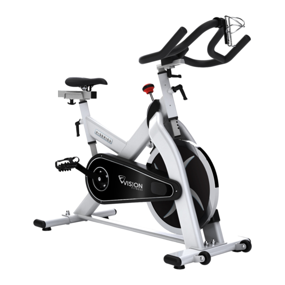
- Page 1 OWNER’S GUIDE V-SERIES Indoor Cycle...
- Page 2 The key to reaping these benefi ts is to develop the exercise habit. Your new indoor cycle will be an important tool to help your members achieve this exercise habit. This Owner’s Guide provides you with basic information on using the VISION FITNESS V-Series indoor cycle.
-
Page 3: Table Of Contents
V-SERIES TABLE OF CONTENTS Important precautions page 4 Before you begin page 5 How to assemble the VISION V-series page 6-8 Initial install checks page 9 How to adjust the VISION V-series page 10 Pedal strap adjustment page 10 Saddle height adjustment... -
Page 4: Important Precautions
Place the Vision V-Series indoor cycle on a level surface. To protect the fl oor or carpet from da- mage, place a mat beneath the cycle. Make sure that there is adequate room around the Vision V-Series indoor cycle to mount, dismount, and operate. -
Page 5: Before You Begin
Maintenance Feet Cover You will fi nd the production code on the left side of the Vision V-Series within the lower range of the frame. Please record this number on your service and maintenance list for easy reference. Page 5... -
Page 6: How To Assemble The Vision V-Series
V-SERIES HOW TO ASSEMBLE VISION V-Series SW 17mm 15mm Pedal SW 14mm hand tight Wrench Assure that black rubber washer is placed Assure that plastic gasket is placed between between upper frame and bolt/washer. rear stabilizer and frame. Assure that plastic gasket is placed between Assure that black rubber washer is placed between upper frame and bolt/washer. - Page 7 V-SERIES HOW TO ASSEMBLE VISION V-Series SW 17mm SW 14mm hand tight 15mm Pedal Wrench STOP mark Make sure the seat is fi xed properly in a LEVEL HORIZONTAL position and securely tightened! Page 7...
- Page 8 V-SERIES HOW TO ASSEMBLE VISION V-Series SW 17mm 15mm Pedal SW 14mm hand tight Wrench STOP mark Pedal marked R installed on right crank (clockwise). Pedal marked L installed on left crank (counter-clockwise) Pedals must be fastened with signifi cant strength and a 15 mm pedal wrench to avoid loosening during use.
-
Page 9: Initial Install Checks
The cycle tune-up must be performed at initial installation of the VISION V-Series for optimal performance and longevity. Please read and follow all instructions below. If the VISION V-Series is not installed and tuned as described, components may wear excessively and the VISION V-Series may become damaged. If you have questions about the installation, please contact Vision Fitness. -
Page 10: How To Adjust The Vision V-Series
V-SERIES HOW TO ADJUST THE VISION V-Series The Vision V-Series can be adjusted for maximum comfort and exercise effectiveness. The instructions below describe one approach to adjusting the cycle to ensure optimal user comfort and ideal body positioning; you may choose to adjust this cycle differently. -
Page 11: Saddle Horizontal Adjustment
V-SERIES HOW TO ADJUST THE VISION V-Series Saddle horizontal adjustment: Proper horizontal adjustment of the saddle is very important in avoiding injury to the knees. Sit on the saddle and move the pedals until the crank arms are in a horizontal position. -
Page 12: Handlebar Adjustment
First, dismount the Vision V-Series indoor cycle; next, turn the front adjustment knob counter clockwise, slide the handlebar post up or down, and then retighten the adjustment knob. -
Page 13: Resistance Adjustment
How to move the VISION V-series: Due to the weight of the Vision V-Series indoor cycle, it is recommended that two people move it. While one person lifts the back of the cycle, the second person fi rmly holds the handlebars and tips the cycle down until it rolls on the wheels. -
Page 14: Preventative Maintenance
WD40, Brunox or any other solvent free lubricant. Daily maintenance: Make sure the Vision V-Series is level. If the Vision V-Series indoor cycle rocks on your fl oor, turn the leveling feet underneath the front or rear stabilizer until the rocking motion is eliminated. -
Page 15: Bi-Weekly Maintenance
V-SERIES PREVENTATIVE MAINTENANCE Bi-weekly maintenance: The Vision V-Series indoor cycle should not be used if the emergency brake system is not working properly. While sitting on the saddle and pedaling, test the brake by pushing the brake downward. The fl ywheel should come to a quick and complete stop. -
Page 16: Monthly Maintenance
V-SERIES PREVENTATIVE MAINTENANCE To maintain easy adjustability of the handlebar post, the handlebar post should be cleaned and lubricated. First, turn the front adjustment knob counter clockwise and slide the handlebar post out of the frame. Apply a small amount of lubricant spray to a lint-free cloth and clean the handlebar post (A). - Page 17 Then, turn the resistance knob counter-clockwise until it stops. Some parts of the Vision V-Series indoor cycle may become loose as result of repeated use. Check pedals and toe straps to make sure they are properly tightened.
-
Page 18: Belt Drive System
V-SERIES PREVENTATIVE MAINTENANCE 5. Belt drive Important: A loose belt as well as an over tightened belt may cause injury of the rider or damage to the system. Checking belt tension: To check for a loose belt, sit on the saddle, place your feet on the pedals, move the pedals until the crank arms are horizontal. -
Page 19: Maintenance Activity Plan & Check Lists
V-SERIES MAINTENANCE ACTIVITY AND REQUIRED SCHEDULE Activity Rotation Details found on Feet levelling, disinfection and cleaning of the bike daily page 14 Servicing brake pads, detailed cleaning of the entire bike weekly page 14 Check emergency brake function bi-weekly page 15... -
Page 20: Exploded Drawings Of Structural Components
V-SERIES SPARE PARTS Drive Gear Parts 02 40 C MD20 08 02 40 BPG 02 40 90 (4 pcs. set) 02 40 CRMO L E 08 02 40 CRMO R E 08 02 40 C 2RS (4pcs.) 02 40 C S 08... - Page 21 V-SERIES SPARE PARTS Flywheel 02 40 H L (4pcs. set) 02 40 02 (2 pcs. set) 02 40 BPK 02 40 H (set) 02 40 08 V (set) incl. 02 40 H 02 40 H L (4pcs. set) Handlebar 02 30 01 V (set)
- Page 22 V-SERIES SPARE PARTS Chain Guard 02 42 01 E 08 02 42 02 V 02 42 03 V 02 42 04 02 42 04 02 99 03: bolts M4 x 15 for chain guard mounting Frame 02 10 A V (3pcs.
- Page 23 V-SERIES SPARE PARTS Saddle Support 0121 VL-3125 SW 02 21 AK 02 21 01 MYR 02 21 01 MYR PK (2 pcs.) 02 10 K 02 20 02 02 20 01 V 02 10 J POP PIN for horizontal saddle stem...
- Page 24 V-SERIES SPARE PARTS Rear Stabilizer 02 11 02 V 02 11 V (4 pcs. set) 02 11 06 V 02 11 05 B MYR 02 11 01 V Front Stabilizer 02 11 A MYR (2 pcs.) 02 11 06 V 02 11 05 B MYR 02 11 V (4pcs.
-
Page 25: Spare Part Reference List
01 40 A Combi-Pedals (pair) Handlebar 01 40 A 3 Toe strap (pair) 02 30 01 V V-series handlebar (set) Brake Parts 02 10 J Pop pin adj. knob 02 50 A Brake adjustment knob 02 11 H Lever handle horztl. -
Page 26: Limited Warranty
V-SERIES WARRANTY TERMS Vision Fitness warrants that all new equipment will be free from manufacturing defects in workmanship and materials, becoming effective on the date of purchase. Parts repaired or replaced under the terms of the warranty will be warranted for the remainder of the original warranty period only. - Page 27 fi tness equipment by any other than an authorized service technician. All repairs attempted by you on your fi tness equipment are undertaken AT YOUR OWN RISK and Vision Fitness shall have no liability for any injury to the person or property arising from such repairs.
- Page 28 V-SERIES COMMERCIAL WARRANTY VISION FITNESS warrants the Vision V-Series indoor cycle for use in commercial facilities including: hotels, resorts, police and fi re stations, apartment complexes, corporate fi tness centers, hospitals, rehabilitation and sports medicine clinics, where average use is up to six hours per day.