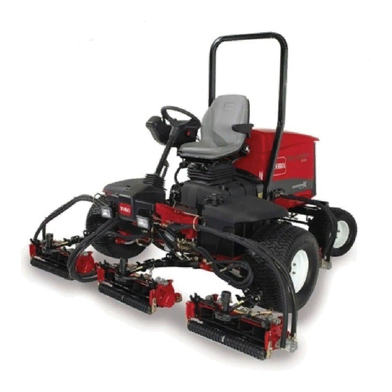
Toro 03608 Reelmaster 5410-G Operator's Manual
Traction unit
Hide thumbs
Also See for 03608 Reelmaster 5410-G:
- Operator's manual (48 pages) ,
- Service manual (662 pages)

Related Manuals for Toro 03608 Reelmaster 5410-G


Summary of Contents for Toro 03608 Reelmaster 5410-G
- Page 1 Form No. 3391-854 Rev A Reelmaster ® 5410-G or 5510-G Traction Unit Model No. 03608—Serial No. 315000001 and Up Model No. 03609—Serial No. 315000001 and Up *3391-854* A Register at www.Toro.com. Original Instructions (EN)
- Page 2 You are responsible for operating the product properly and safely. You may contact Toro directly at www.Toro.com for product safety and operation training materials, accessory information, help finding a dealer, or to register your product.
-
Page 3: Table Of Contents
Belt Maintenance ............42 Safety ................4 Tensioning the Alternator Belt .........42 Safe Operating Practices........... 4 Hydraulic System Maintenance ........42 Toro Riding Mower Safety ........6 Changing the Hydraulic Fluid........42 Safety and Instructional Decals ......... 7 Replacing the Hydraulic Filters .........43 Setup ................10 Checking the Hydraulic Lines and Hoses....43... -
Page 4: Safety
Safety • Evaluate the terrain to determine what accessories and attachments are needed to properly and safely perform the job. Only use accessories and attachments approved Improper using or maintaining the machine can result by the manufacturer. in injury. To reduce the potential for injury, comply with •... -
Page 5: Maintenance And Storage
• – Stay alert for humps and hollows and other hidden Lightning can cause severe injury or death. If lightning hazards. is seen or thunder is heard in the area, do not operate the machine; seek shelter. – Do not turn sharply. Use care when reversing. •... -
Page 6: Toro Riding Mower Safety
Do not resume The following list contains safety information specific to Toro mowing until the area is cleared. products or other safety information that you must know that is not included in the CEN, ISO, or ANSI standard. -
Page 7: Safety And Instructional Decals
Safety and Instructional Decals Safety decals and instructions are easily visible to the operator and are located near any area of potential danger. Replace any decal that is damaged or lost. 93-6681 98-4387 1. Cutting/dismemberment—hazard, fan-stay away from moving parts. 1. - Page 8 110-8921 106-6755 1. Traction unit speed 1. Engine coolant under 3. Warning—do not touch the 2. Slow pressure. hot surface. 3. Fast 2. Explosion hazard—read 4. Warning—read the the Operator's Manual. Operator's Manual. 110-9642 1. Stored energy hazard—read the Operator's Manual. 110-8869 2.
- Page 9 Battery Symbols Some or all of these symbols are on your battery 1. Explosion hazard 6. Keep bystanders a safe distance from the battery. 2. No fire, open flame, or 7. Wear eye protection; smoking. explosive gases can cause blindness and other injuries 8.
-
Page 10: Setup
Setup Loose Parts Use the chart below to verify that all parts have been shipped. Procedure Description Qty. – No parts required Adjust the tire pressure. – No parts required Adjust the step height. – No parts required Adjust the control arm position. Front hose guide (right-hand) Install the cutting units. -
Page 11: Adjusting The Control Arm Position
Figure 2 1. Step 2. Step brackets Figure 3 1. Control arm 3. Bolts (2) 2. Raise or lower the step to the desired height and 2. Retaining brackets re-secure the brackets to the frame with the 2 bolts and nuts. 2. - Page 12 Figure 6 1. Opposite carrier frame tab 2. Rod bracket D. Mount the rod bracket to the cutting unit tabs with the carriage bolts and nuts (Figure Important: On the #4 (left front) and #5 (right front) cutting units (Figure 7), use the rod bracket mounting nuts to install the hose guides to the front of the cutting unit...
- Page 13 g019284 Figure 9 1. Hose guides (each must lean toward the center cutting unit) Note: When installing or removing the cutting units, make sure the hairpin cotter is installed in the spring rod hole next to the rod bracket. When not installing or removing the cutting units, the hairpin cotter must be installed in the hole in the end of the rod.
-
Page 14: Adjusting The Turf Compensation Spring
B. Insert the lift arm yoke onto the carrier frame shaft (Figure 11). C. Insert the lift arm shaft into the lift arm and secure it with the washer and lynch pin (Figure 12). 10. Insert the cap over the carrier frame shaft and lift arm yoke. -
Page 15: Using The Cutting Unit Kickstand
Figure 15 1. Turf compensation spring 3. Spring rod 2. Hairpin cotter 4. Hex nuts Figure 16 1. Cutting unit kickstand 2. Tighten the hex nuts on the front end of the spring rod until the compressed length of the spring is 12.7 cm (5 inches) on Reelmaster 5410, 5 inch cutting units Secure the kickstand to the chain bracket with the snapper or 15.9 cm (6.25 inches) on Reelmaster 5510, 7 inch... -
Page 16: Product Overview
Product Overview how far you press the pedal. For no load, maximum ground speed, fully press the pedal while the engine speed setting is in the Fast position. To stop, reduce foot pressure on the traction pedal and allow it to return to the center position. Figure 18 1. -
Page 17: Key Switch
increase or decrease the engine speed in 100-rpm increments. By holding the switch down, the engine speed automatically moves to High or Low idle, depending on which end of the switch you press. G021208 Figure 21 g021209 1. Lower mow/raise control 4. - Page 18 InfoCenter Icon Description SERVICE DUE Indicates when scheduled service should be performed Engine rpm/status—indicates the engine speed Hour meter Info icon Fast Slow Figure 24 1. Power point Fuel level Using the InfoCenter LCD Display Stationary regeneration required The InfoCenter LCD display shows information about your machine such as the operating status, various diagnostics and other information about the machine (Figure...
- Page 19 Indicates when the cutting units are faults. Refer to the Service being raised Manual or your Authorized Toro Distributor for more PIN passcode information on the Faults menu and the information contained there. CAN bus...
- Page 20 Engine Run Indicates the inputs, qualifiers Machine Controller Revision Lists the software revision of and outputs for starting the the master controller. engine. InfoCenter Revision Lists the software revision of Backlap Indicates the inputs, qualifiers the InfoCenter. and outputs for operating the CAN Bus Lists the machine backlap function.
- Page 21 Setting the Blade Count • In the Settings Menu, scroll down to Blade Count. • Press the right button to change the blade count between 5, 8, or 11 blade reels. Setting the Mow Speed • In the Settings Menu, scroll down to Mow Speed. •...
-
Page 22: Specifications
Contact your Authorized Service Dealer or Distributor or go to www.Toro.com for a list of all approved CAUTION attachments and accessories. If you leave the key in the ignition switch, someone could accidently start the engine and seriously injure you or other bystanders. -
Page 23: Checking The Cooling System
The cooling system is filled with a 50/50 solution of water Above 25 degrees C (77 SAE30 or SAE 10W-30 degrees F) SAE 15W-40 and permanent ethylene glycol antifreeze. Check the level of the coolant in the expansion tank at the beginning of each day 0 degrees C to 25 degrees C SAE20 or SAE 10W-30 before starting the engine. -
Page 24: Checking The Hydraulic Fluid
such as E15 (contains 15% ethanol), E20 (contains DANGER 20% ethanol), or E85 (contains up to 85% ethanol). In certain conditions during fueling, static Using unapproved gasoline may cause performance electricity can be released causing a spark which problems and/or engine damage which may not be can ignite the fuel vapors. - Page 25 Water content (new fluid) 500 ppm (maximum) Industry Specifications: Alternative fluids: If the Toro fluid is not available, other Vickers I-286-S, Vickers M-2950-S, Denison HF-0, conventional, petroleum-based fluids may be used, provided Vickers 35 VQ 25 (Eaton ATS373-C)
-
Page 26: Checking The Reel To Bedknife Contact
Starting and Stopping the Engine Starting the Engine 1. Sit on the seat, keep your foot off of the traction pedal so that it is in Neutral, engage the parking brake, set the engine speed switch to the Mid position and ensure that the Enable/Disable switch is in the Disable position. -
Page 27: Adjusting The Lift Arm Turn Around Position
2. Insert a tube or similar object onto the long spring end and pivot it around the spring actuator to the desired position (Figure 30). CAUTION The springs are under tension. Use caution when adjusting them. Figure 31 1. Switch 2. -
Page 28: Locating The Jacking Points
Important: Running the engine with the bypass valve open causes the transmission to overheat. Locating the Jacking Points Note: Use jack stands to support the machine when required. • Front—rectangular pad, under the axle tube, inside each front tire (Figure Figure 34 1. -
Page 29: Checking The Interlock Switches
When a fault message is displayed, the light blinks until the 5. If a switch is closed and the appropriate indicator does fault is resolved not change, check all wiring and connections to the switch and/or check the switches with an ohm meter. Replace any defective switches and repair any defective wiring. -
Page 30: Operating Tips
Operating Tips Becoming Familiar with the Machine Before mowing grass, practice operating the machine in an open area. Start and stop the engine. Operate in forward and reverse. Lower and raise the cutting units and engage and disengage the reels. When you feel familiar with the machine, practice operating up and down slopes at different speeds. -
Page 31: Maintenance
Maintenance Note: Determine the left and right sides of the machine from the normal operating position. Recommended Maintenance Schedule(s) Maintenance Service Maintenance Procedure Interval • Torque the wheel lug nuts to 94 to 122 N-m (70 to 90 ft-lb). After the first hour •... -
Page 32: Daily Maintenance Checklist
2. Immediately after every washing, regardless of the interval listed Notation for Areas of Concern Inspection performed by: Item Date Information Important: Refer to your engine operator's manual for additional maintenance procedures. Note: To obtain an electrical schematic or a hydraulic schematic for your machine, visit www.Toro.com. -
Page 33: Service Interval Chart
Service Interval Chart Figure 37 CAUTION If you leave the key in the ignition switch, someone could accidently start the engine and seriously injure you or other bystanders. Remove the key from the ignition before you do any maintenance. Lubrication Greasing the Bearings and •... - Page 34 • • Cutting unit carrier frame and pivot (2 each) (Figure Axle steering pivot (1) (Figure Figure 43 • Steering cylinder ball joints (2) (Figure Figure 40 • Lift arm pivot shaft (1 each) (Figure Figure 41 Figure 44 • Rear axle tie rod (2) (Figure •...
-
Page 35: Engine Maintenance
Engine Maintenance Servicing the Air Cleaner Check the air-cleaner body for damage which could cause an air leak. Replace if damaged. Check the whole intake system for leaks, damage or loose hose clamps. g021218 Service the air-cleaner filter only when the service indicator Figure 47 (Figure 46) requires it. -
Page 36: Replacing The Spark Plugs
Figure 50 1. Air gap 5. Install the correctly gapped spark plug with gasket seal, g021213 and tighten the plug to 25 to 30 N-m (18 to 21.6 ft-lb). If a torque wrench is not used, tighten the plug firmly. Figure 49 1. -
Page 37: Fuel System Maintenance
Fuel System Maintenance Replacing the Fuel Filter DANGER In certain conditions, gasoline is extremely flammable and highly explosive. A fire or explosion g021236 from gasoline can burn you and others and can damage property. Figure 52 • Drain gasoline from the fuel tank when the 1. -
Page 38: Electrical System Maintenance
Checking the Fuses Electrical System Maintenance There are 8 fuses in the electrical system. The fuse block (Figure 53) is located behind the control arm access panel. Important: Before welding on the machine, disconnect both cables from the battery, both wiring harness plugs from the electronic control module, and the terminal connector from the alternator to prevent damage to the electrical system. -
Page 39: Drive System Maintenance
Drive System 5. Tighten the locknut to secure the adjustment. 6. Stop the engine. Remove the jack stands and lower the Maintenance machine to the shop floor. 7. Test drive the machine to make sure it does not creep. Adjusting the Traction Drive Adjusting the Rear Wheel for Neutral Toe-in... -
Page 40: Cooling System Maintenance
Cooling System Maintenance Removing Debris from the Cooling System Remove debris from the screen and radiator/oil cooler daily (more frequently in dirty conditions). 1. Turn the engine off and remove the key from the ignition switch. 2. Thoroughly clean all debris out of the engine area. 3. -
Page 41: Brake Maintenance
Brake Maintenance Adjusting the Parking Brake If the parking brake fails to engage, an adjustment to the brake pawl is required. Adjusting the Service Brakes 1. Loosen the 2 screws securing the parking brake pawl Adjust the service brakes when there is more than 25 mm (1 to the frame (Figure 61). -
Page 42: Belt Maintenance
Change hydraulic fluid after every 800 operating hours, in normal conditions. If fluid becomes contaminated, contact 1. Open the hood. your local Toro distributor because the system must be 2. Check the tension of the alternator belt by pressing on flushed. Contaminated fluid looks milky or black when it, with moderate thumb pressure, midway between the compared to clean oil. -
Page 43: Replacing The Hydraulic Filters
Replacing the Hydraulic Filters The hydraulic system is equipped with a service interval indicator (Figure 64). With the engine running at operating temperature, view the indicator, it should be in the Green zone. When the indicator is in the Red zone, change the hydraulic filters. -
Page 44: Using The Hydraulic System Test Ports
Use the hydraulic system test ports to test the pressure in Use the test port on the lift manifold block (Figure 69) to the hydraulic circuits. Contact your local Toro distributor for assist in troubleshooting the lift circuit. assistance. Use the test ports on the front hydraulic tubes... -
Page 45: Cutting Unit System Maintenance
Cutting Unit System stabilizes, then return the reel speed to your desired speed. Maintenance 9. To make an adjustment to the cutting units while backlapping, turn the reels off by moving the Lower Mow/Raise lever rearward; the Enable/Disable switch Backlapping the Cutting Units to the Disable position, and stop the engine. -
Page 46: Storage
13. Seal the air cleaner inlet and the exhaust outlet with C. Coat the cable terminals and battery posts with weatherproof tape. Grafo 112X skin-over grease (Toro Part 505-47) or petroleum jelly to prevent corrosion. 14. Check the antifreeze protection and add antifreeze/coolant as needed for the expected D. - Page 47 Notes:...
- Page 48 Countries Other than the United States or Canada Customers who have purchased Toro products exported from the United States or Canada should contact their Toro Distributor (Dealer) to obtain guarantee policies for your country, province, or state. If for any reason you are dissatisfied with your Distributor's service or have difficulty obtaining guarantee information, contact the Toro importer.