
Related Manuals for Omega Engineering 450 Series


Summary of Contents for Omega Engineering 450 Series
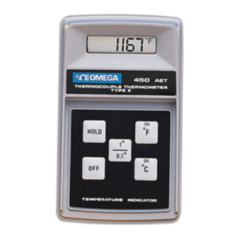
- Page 1 MADE IN 305.4 ® THERMOCOUPLE THERMOMETER TYPE E HOLD 1° 0.1° TEMPERATURE INDICATOR Digital Thermometers User’ s Guide °F 450 AET Shop online at °F e-mail: info@omega.com °C 450 SERIES www.omega.com...
- Page 2 OMEGAnet www.omega.com USA: One Omega Drive, Box 4047 ISO 9001 Stamford CT 06907-0047 Certified Tel: (203) 359-1660 e-mail: info@omega.com Canada: 976 Bergar Laval (Quebec) H7L 5A1, Canada Tel: (514) 856-6928 e-mail: info@omega.ca For immediate technical or application assistance: USA and Sales Service: 1-800-826-6342 / 1-800-TC-OMEGA Canada: Customer Service: 1-800-622-2378 / 1-800-622-BEST...
- Page 3 Benelux: Postbus 8034, 1180 LA Amstelveen The Netherlands Tel: +31 (0)20 3472121 FAX: +31 (0)20 6434643 Toll Free in Benelux: 0800 0993344 e-mail: sales@omegaeng.nl Czech Republic: Frystatska 184, 733 01 Karvina ´, Czech Republic Tel: +420 (0)59 6311899 FAX: +420 (0)59 6311114 Toll Free: 0800-1-66342 e-mail: info@omegashop.cz France:...
-
Page 4: Table Of Contents
Table of Contents Section 1: Description 1.1 General Description……………2 1.2 Physical Description…………...3 1.3 Unpacking……………………… 3 1.4 Specification…………………… 4 Section 2: Operation 2.1 Principles of Operation………...7 2.2 Power…………………………… 8 2.3 Operation……………………….10 2.4 Maintenance……………………13 Section 3: Calibration 3.1 Calibration………………………14... -
Page 5: Section 1: Description
Section 1 Description 1.1 General Description Your hand-held, battery operated digital temperature indicator is configured for compatibility with one of five temperature transducers, J,K,E,T RTD and Thermister. Each of the configurations linearizes the analog output from the transducer to produce a stable and accurate digital temperature display. -
Page 6: Physical Description
1.2 Physical Description The indicator measures 45 mm (1.8 inches) in Height, 85 mm (3.3 inches) in width, and 145 mm (5.7 inches) in length. Weight is 230 grams (8.0 ounces). The case is constructed of high impact plastic. 1.3 Unpacking The indicator is supplied with the battery installed. -
Page 7: Specification
Specifications Display: Liquid crystal display, 7.6 mm (0.3 in.) digit Height Operating temperature: 0 to 50 C (32 to 122 F) 0 to 75% Relative Humidity Storage Temperature: -20 to 70 C (-4 to 158 F) Battery: NEDA 1604, 9 Volt Battery Life: Thermocouple-2000 hours minimum Platinum RTD-500 hours minimum... - Page 8 Maximum Common Mode Voltage: 1000VAC(RMS), 2000V Peak Accuracy at 22 C (72 F) 1 range: 0.1 range: Stability with time: 90 days: 1 year: Stability with temperature: Thermocouple: zero: 0.03 C/ C span: 0.02% rdg/ C (max) reference junction tracking 1.0 C ( 1.8 F) from 5 C to 45 C (41 F to 113 F) Platinum RTD: 0.02 C, 0.01% rdg/ C Thermistor: positive- 0.02 C/ C...
- Page 9 450 Range Table Type Type Type Type Thermister -189 C to +1372 C -308 F to +2501 F -139.8 C to +203.7 C -219.7 F to +398.7 F -194 C to +1200 C -318 F to +2192 F -117.4 C to +203.5 C -179.4 F to +398.7 F...
-
Page 10: Section 2: Operation
Section 2 Operation 2.1 Principles of Operation The temperature indicator uses two ICs to digitize and display the analog input signal. One IC performs the conversion of the analog input to the digital equivalent via 24 bit delta- sigma analog to digital converter. Battery voltage is also monitored by this IC and a thermistor supplies the reference junction correction signal. -
Page 11: Power
2.2 Power When battery voltage reaches about 6 volts, the display will exhibit a flashing: “LOW BAT” indication. A minimum of 20 hours of operation time remains upon initial appearance of the “LOW BAT” indication. When the battery voltage drops below 5 volts, an overload indications of three columns of dashes will appear on the display in addition to the flashing “LOW BAT”... - Page 12 the recesses or each corner of the case bottom. Step 2: Carefully pull the case halves straight apart so as not to damage the internal connectors. Step 3. Install the new battery. Close the case and reinstall the four screws.
-
Page 13: Operation
2.3 Operation Step 1: Insert temperature sensor plug into the indicator input jack. Failure to insert a probe results in a overload condition of three columns of dashes showing on the display. Step 2: Turn the indicator ON by pressing the F or C key. - Page 14 Step 5: Observe and or record the temperature value. Step 6: Turn instrument off by pressing the OFF key.
- Page 15 To Hold Display Press and hold key to retain last reading on the display. Press this key to turn OFF Range Selector Operation Features Display Value Indication 450 SERIES HOLD Press C or F keys to turn ON and/or temperature scale...
-
Page 16: Maintenance
2.4 Maintenance Normal maintenance of the indicator consists of occasional cleaning with a soft, damp cloth, replacement of the battery as required, and calibration as outlined in Section 3. -
Page 17: Section 3: Calibration
Section 3 Calibration 3.1 Calibration Units with serial numbers beginning with the letter N use the calibration procedure outlined below. Older units do not display version numbers and use the calibration procedures on page 19 . The calibration procedure should be performed by a qualified instrumentation service technician. - Page 18 with a minimum accuracy of ±0.1 degree Fahrenheit or ±0.2 degree Centigrade. Step 1. Ensure the unit is turned off. Connect the the input output of the thermocouple simulator to indicator using appropriate thermocouple wire. Set the simulator output to 0 C Step 2.
- Page 19 NOTE: If you want to cancel the calibration mode press OFF button in front of the unit. For T/C type Press the switch one more time and wait for a few seconds until display switches to 0.0 set simulator to 0 C. Press switch one more time. Unit should shut-off.
- Page 20 calibration procedure, set simulator at .2 C instead of 0 C. Repeat the calibration procedure again. Step 6. Verify calibration once finished.
- Page 21 Ref J -1.23V +3.7V Ra - Full Scale Adj. Rb Zero Adj. Rc +Full Scale Adj.
- Page 22 Calibration- Thermocouple Type K, J and and E Equipment List 4 ½ digit voltmeter Voltage Calibrator: Resolution, 1uV; accuracy 0.01% ( 2uV) Ice Bath, 0.00 C Jumper lead terminated in mini-clips For optimum results, the calibration should be performed with an ambient temperature from 20 24 C (68 to 75 F).
- Page 23 Remove the bottom case of the indicator. Adjust the voltage calibrator for an output of 0.000mV and connect the minus lead from the calibrator to “GND” and the positive lead from the calibrator to “;+IN”, on the indicator printed circuit board. Disable the reference junction by jumpering together the “REF J”...
- Page 24 polrity). The voltage measured at the “3.7V” test- point should be 3.007 times larger than the voltage measured at the “-1.23V” test- point. Adjust Rc (which varies the +3.7V line to attain the proper ratio. Switch the indicator to the 1 range. Adjust the voltage calibrator for an output of +53.782mV for type K;...
- Page 25 Calibration- Thermistor Type Equipment List 4 ½ digit voltmeter Precision decade box: Resolution, 0.01 ohm ; accuracy 0.02% Ice Bath, 0.00 C Electro Scientific Industries DB-62 or equivalent Turn the indicator ON by pressing the C key. Remove the bottom case of the indicator. Connect a precision resistance box to the terminals on the phone input jack;...
- Page 26 at the “-1.23V” testpoint: disregarding polarity indication, record the voltage. Move the DVM HI lead to the “3.7V” testpoint and record the voltage (disregard polarity). The voltage measured at the “3.7V” test- point should be 3.007 times larger than the voltage measured at the “-1.23V” test- point.
- Page 27 Calibration- Platinum RTD Equipment List 4 ½ digit voltmeter Precision decade box: Resolution, 0.01 ohm ; accuracy 0.02% Ice Bath, 0.00 C Electro Scientific Industries DB-62 or equivalent Turn the indicator ON by pressing the C key. Remove the bottom case of the indicator. Connect a precision resistance box to the terminals on the RTD input jack and set the resistance box to 100.04 ohms.
- Page 28 Move the DVM HI lead to the “3.7V” testpoint and record the voltage (disregard polrity). The voltage measured at the “3.7V” test- point should be 3.007 times larger than the voltage measured at the “-1.23V” test- point. Adjust Rc (which varies the +3.7V line to attain the proper ratio.
- Page 29 Zero Calibration Turn the indicator on by pressing the C key. Set the indicator to the 0.1 range. Connect the ice bath probe to the indicator Input jack. Place the probe in a stable ice bath (0.00C 0.05 C and adjust the ZERO pot (Rb) located beneath the plug on the rear case for an indicator display of 0.0 C.
- Page 30 WARRANTY/DISCLAIMER OMEGA ENGINEERING, INC. warrants this unit to be free of defects in materials and workmanship for a period of 13 months from date of purchase. OMEGA’s Warranty adds an additional one (1) month grace period to the normal one (1) year product warranty to cover handling and shipping time.
- Page 31 Where Do I Find Everything I Need for Process Measurement and Control? Shop online at www.omega.com TEMPERATURE Thermocouple, RTD & Thermistor Probes, Connectors, Panels & Assemblies Wire: Thermocouple, RTD & Thermistor Calibrators & Ice Point References Recorders, Controllers & Process Monitors Infrared Pyrometers PRESSURE, STRAIN AND FORCE...