Table of Contents
Advertisement
Advertisement
Table of Contents

Related Manuals for Asus VIVOMINI VC65 SERIES


Summary of Contents for Asus VIVOMINI VC65 SERIES
- Page 1 VivoMini VC65 Series User Manual...
- Page 2 ASUS will only be responsible for or indemnify you for loss, damages or claims based in contract, tort or infringement under this Warranty Statement. This limit also applies to ASUS’ suppliers and its reseller. It is the maximum for which ASUS, its suppliers, and your reseller are collectively responsible.
-
Page 3: Table Of Contents
Quickly enter the BIOS ..................20 Upgrading your VivoMini Installing 2.5” hard disk drive / solid state drive ........22 Upgrading memory modules ..............27 Appendix Safety information ...................32 Setting up your system.................32 Care during use ....................32 Regulatory notices ...................34 ASUS contact information ................40 VivoMini VC65 Series... -
Page 4: About This Manual
VivoMini's data and components. Typography Bold text Indicates a menu or an item to select. Italic This indicates sections that you can refer to in this manual. VivoMini VC65 Series... -
Page 5: Package Contents
• **The availability and quantity of these items vary with your VivoMini package. • If the device or any of its components fail or malfunction during normal or proper use and it is still within the warranty period, bring the device and the warranty card to you nearest ASUS Service Center. VivoMini VC65 Series... - Page 6 VivoMini VC65 Series...
-
Page 7: Getting To Know Your Vivomini
Getting to know your VivoMini... -
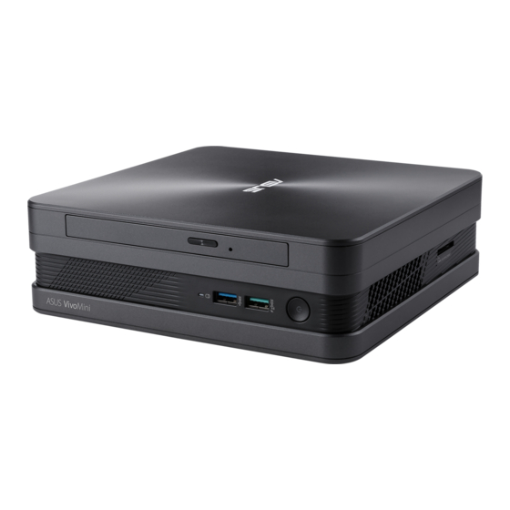
Page 8: Features
5 Gbit/s and is backward compatible to USB 2.0. Power button The power button allows you to turn the VivoMini on or off. You can also press the power button once to put your VivoMini to sleep mode. VivoMini VC65 Series... -
Page 9: Left Side
The air vents allow air to exit your VivoMini chassis. IMPORTANT! For optimum heat dissipation and air ventilation, ensure that the air vents are free from obstructions. Memory card slot This built-in memory card reader slot supports MMC, SD, SDHC, and SDXC card formats. VivoMini VC65 Series... -
Page 10: Rear Panel
The Kensington® security slot allows you to secure your VivoMini using Kensington® compatible VivoMini security products. DisplayPort The DisplayPort sends high-performance digital output from your VivoMini to a display device such as an LCD TV or HD monitor. VivoMini VC65 Series... -
Page 11: Lan Port
5 Gbit/s and is backward compatible to USB 2.0. HDMI port The HDMI (High Definition Multimedia Interface) port supports a Full-HD device such as an LCD TV or monitor to allow viewing on a larger external display. VivoMini VC65 Series... - Page 12 Air vents The air vents allow air to enter your VivoMini chassis. IMPORTANT! For optimum air flow, ensure that the air vents are free from obstructions. VivoMini VC65 Series...
-
Page 13: Using Your Vivomini
Using your VivoMini... -
Page 14: Getting Started
Plug the AC power cord into a 100V~240V power source. IMPORTANT! • We strongly recommend that you use only the AC power cord that came with your VivoMini. • We strongly recommend that you use a grounded wall socket while using your VivoMini. • The socket outlet must be easily accessible and near your VivoMini. • To disconnect your VivoMini from its main power supply, unplug your VivoMini from the power socket. • Power adapter information: Rating: 100~240V~, 50-60Hz, 1.5A VivoMini VC65 Series... -
Page 15: Connect A Display Panel To Your Vivomini
NOTE: The HDMI to DVI adapter, DisplayPort to DVI adapter, or VGA to DVI adapter are each sold separately. To connect a display panel to your VivoMini: Connect a display cable either to the HDMI, DisplayPort or VGA port. Connecting display via HDMI port Connecting display via DisplayPort port VivoMini VC65 Series... - Page 16 Connecting display via VGA port VivoMini VC65 Series...
-
Page 17: Connect The Usb Cable From Keyboard Or Mouse
To connect a keyboard and mouse to your VivoMini: Connect the USB cable from your keyboard and mouse to any of the USB ports of your VivoMini. Connecting keyboard or mouse via USB port VivoMini VC65 Series... -
Page 18: Turn On Your Vivomini
Turn on your VivoMini Press the power button to turn on your VivoMini. VivoMini VC65 Series... -
Page 19: Turning Your Vivomini Off
• An error message appears on the screen during the system bootup and requests you to run the BIOS Setup. • You have installed a new system component that requires further BIOS settings or update. WARNING! Inappropriate BIOS settings may result to instability or boot failure. We strongly recommend that you change the BIOS settings only with the help of a trained service personnel. VivoMini VC65 Series... -
Page 20: Quickly Enter The Bios
VivoMini’s power connector. Reconnect the power cable and press the power button to turn on your VivoMini. Press <F2> or <Del> during POST. NOTE: POST (Power-On Self Test) is a series of software controlled diagnostic tests that run when you turn on your PC. VivoMini VC65 Series... -
Page 21: Upgrading Your Vivomini
Upgrading your VivoMini... -
Page 22: Installing 2.5" Hard Disk Drive / Solid State Drive
Remove the screw from the top cover lock latch and push the latch down (A and B), then slide the top cover towards the rear of your VivoMini (C) until it is detached from the chassis. Lift and remove the top cover (D) and set it aside. VivoMini VC65 Series... - Page 23 Remove four (4) screws from the HDD/SSD bracket. HDD1R HDD1L (optional) To upgrade your HDD/SDD, first remove the four (4) screws on the bracket, then remove the bracket. VivoMini VC65 Series...
- Page 24 • T he availablility of the holder may vary depending on the model type, country, or region. Connect the cable to the HDD1L, HDD1R and PWR1 connectors in your VivoMini. HDD1L HDD1R HDD1L HDD1R Connect Connect Connect to HDD1L to PWR1 to HDD1R connector connector connector HDD1L PWR1, HDD1R VivoMini VC65 Series...
- Page 25 HDD/SSD compartment of your VivoMini and secure the bracket with the screws previously removed. HDD1R HDD1L NOTE: Ensure to organize the cables to prevent any damage to your VivoMini and to ensure the top cover can be replaced successfully. VivoMini VC65 Series...
- Page 26 10. Replace the top cover (A) your VivoMini and slide it towards the front of the VivoMini to re-attach (B), then push the latch up and secure it using a screw (C and D). VivoMini VC65 Series...
-
Page 27: Upgrading Memory Modules
2GB, 4GB, or 8GB unbuffered non-ECC 1.35 V DDR3L 204-pin SO-DIMMs for a maximum of 16GB memory. IMPORTANT! Refer to http://www.asus.com for the list of compatible DIMMs. You can only install 1.35 V DDR3L SO-DIMM to the VivoMini’s DIMM slots. - Page 28 Pry the SO-DIMM slot cover open, then set it aside. NOTE: If you want to remove the SO-DIMM slot cover, use a flathead screwdriver. VivoMini VC65 Series...
- Page 29 Align and insert the memory module into the slot (A) and press it down (B) until it is securely seated in place. Repeat the same steps to install the other memory module. IMPORTANT! Always install into the lower slot first. Replace the SO-DIMM slot cover. VivoMini VC65 Series...
- Page 30 NOTE: Ensure to organize the cables to prevent any damage to your VivoMini and to ensure the top cover can be replaced successfully. Follow step 10 under the Installing 2.5” hard disk drive / solid state drive section to replace the top cover of your VivoMini. VivoMini VC65 Series...
-
Page 31: Appendix
Appendix... -
Page 32: Safety Information
The power cord or plug is damaged. – Liquid has been spilled into the system. – The system does not function properly even if you follow the operating instructions. – The system was dropped or the cabinet is damaged. – The system performance changes. VivoMini VC65 Series... - Page 33 This symbol of the crossed out wheeled bin indicates that the product (electrical, electronic equipment, and mercury-containing button cell battery) should not be placed in municipal waste. Check local technical support services for product recycling. VivoMini VC65 Series...
-
Page 34: Regulatory Notices
REACH Complying with the REACH (Registration, Evaluation, Authorization, and Restriction of Chemicals) regulatory framework, we publish the chemical substances in our products at ASUS REACH website at http://csr.asus.com/english/REACH.htm ASUS Recycling/Takeback Services ASUS recycling and takeback programs come from our commitment to the highest standards for protecting our environment. -
Page 35: Rf Exposure Warning
RF exposure compliance. Declaration of Conformity (R&TTE directive 1999/5/EC) The following items were completed and are considered relevant and sufficient: • Essential requirements as in [Article 3] • Protection requirements for health and safety as in [Article 3.1a] • Testing for electric safety according to [EN 60950] • Protection requirements for electromagnetic compatibility in [Article 3.1b] • Testing for electromagnetic compatibility according to [EN 301 489-1] & [EN 301 489-17] • Effective use of the radio spectrum as in [Article 3.2] • Radio test suites according to [EN 300 328-2] VivoMini VC65 Series... -
Page 36: France Restricted Wireless Frequency Bands
Loir et Cher Loiret Manche Meuse Nièvre Nord Oise Orne Puy du Dôme Pyrénées Atlantique Pyrénées Bas Rhin Orientales Haute Saône Saône et Loire 75 Paris Tarn et Garonne Vaucluse Vosges Yonne Territoire de Val de Marne Belfort VivoMini VC65 Series... -
Page 37: Canadian Department Of Communications Statement
End users must follow the specific operating instructions for satisfying RF exposure compliance. Operation is subject to the following two conditions: • This device may not cause interference and • This device must accept any interference, including interference that may cause undesired operation of the device. VivoMini VC65 Series... -
Page 38: Ce Mark Warning
Wireless Operation Channel for Different Domains N. America 2.412-2.462 GHz Ch01 through CH11 Japan 2.412-2.484 GHz Ch01 through Ch14 Europe ETSI 2.412-2.472 GHz Ch01 through Ch13 Regional notice for Singapore This ASUS product complies with IDA Complies with IDA Standards Standards. DB103778 VivoMini VC65 Series... -
Page 39: Energy Star Complied Product
Department of Energy helping us all save money and protect the environment through energy efficient products and practices. All ASUS products with the ENERGY STAR logo comply with the ENERGY STAR standard, and the power management feature is enabled by default. The monitor and computer are automatically set to sleep after 10 and 30 minutes of user inactivity. -
Page 40: Asus Contact Information
+1-510-739-3777 +1-510-608-4555 Web site http://usa.asus.com Technical Support Support fax +1-812-284-0883 General support +1-812-282-2787 Online support http://qr.asus.com/techserv ASUS COMPUTER GmbH (Germany and Austria) Address Harkort Str. 21-23, D-40880 Ratingen, Germany +49-2102-959931 Web site http://www.asus.com/de Online contact http://eu-rma.asus.com/sales Technical Support Telephone +49-2102-5789555 Support Fax... - Page 41 VivoMini VC65 Series...
- Page 42 VivoMini VC65 Series...
- Page 43 VivoMini VC65 Series...
- Page 44 VivoMini VC65 Series...
- Page 45 VivoMini VC65 Series...
-
Page 46: Declaration Of Conformity
(2) this device must accept any interference received, including interference that may cause undesired operation. Representative Person’s Name : Steve Chang / President Signature : Dec. 09, 2015 Original Declaration Date : Dec. 28, 2015 Corrected Declaration Date : Ver. 140331 VivoMini VC65 Series...