Table of Contents
Advertisement
Quick Links
Advertisement
Table of Contents

Related Manuals for Furuno NX-300-D


Summary of Contents for Furuno NX-300-D
- Page 1 Back NAVTEX RECEIVER NX-300...
- Page 2 Yo u r L o c a l A g e n t / D e a l e r 9 - 5 2 , A s h i h a r a - c h o , N i s h i n o m i y a , J a p a n Te l e p h o n e : 0 7 9 8 - 6 5 - 2 111 Te l e f a x :...
- Page 3 SAFETY INSTRUCTIONS Safety Instructions for the Operator WARNING CAUTION Do not open the cover of Keep heater away from equipment. the equipment. A heater can melt the equipment's power Only qualified personnel cord, which can cause fire or electrical should work inside the shock.
- Page 4 Safety Instructions for the Installer CAUTION WARNING Do not open the cover Ground the equipment to unless totally familiar with prevent mutual interference. electrical circuits and service manual. Confirm that power supply voltage Improper handling can result is compatible with the voltage rating in electrical shock.
-
Page 5: Table Of Contents
CONTENTS FOREWORD........................v A Word to NX-300 Owners ........................v Features ............................vi SYSTEM CONFIGURATION ..................vii EQUIPMENT LISTS ....................viii 1. PRINCIPLE OF NAVTEX SYSTEM................ 1-1 1.1 How NAVTEX Works.......................1-1 1.2 NAVTEX System Operation.....................1-1 1.3 Message Format........................1-2 1.4 Display Indications ........................1-3 1.5 NAVTEX Station Map ......................1-4 1.6 NAVTEX Station List .......................1-5 2. - Page 6 3.5 Delete All Messages........................3-4 3.6 User Display of Navigation Data....................3-4 4. OTHER FUNCTIONS ..................... 4-1 4.1 DEMO Mode...........................4-1 4.2 VIEW Mode ..........................4-1 4.3 All Clear..........................4-1 4.4 Changing Received Message Log Window................4-2 5. MAINTENANCE & TROUBLESHOOTING............. 5-1 5.1 Maintenance ...........................5-1 5.2 Diagnostic Test ........................5-1 5.3 When the Battery Icon Appears....................5-2 5.4 Replacement of Fuse ......................5-3 6.
-
Page 7: Foreword
Our extensive global network of agents and dealers furthers this dedication to excellence. The NX-300 is just one of the many FURUNO developments in the field of marine radio communication. The NX-300 provides cost-effective price, high sensitivity and simple operation in one compact and light-weight unit. -
Page 8: Features
Search and Rescue (SAR) information and other navigational information for NAVTEX receiver-equipped vessels sailing in coastal waters. The FURUNO NX-300 NAVTEX receiver receives NAVTEX messages and automatically displays them together with station ID and message category information. The service range of a NAVTEX station is typically 200-400 nautical miles. A NAVTEX station normally broadcasts every 4 hours. -
Page 9: System Configuration
SYSTEM CONFIGURATION H-field ANTENNA UNIT NX-3H-D Antenna Cable (10 m) NAVTEX RECEIVER NX-300-D FURUNO GPS navigator MENU DISP FREQ Personal Computer Power Cable (2 m) 12-24 VDC NX-300 System configuration... -
Page 10: Equipment Lists
EQUIPMENT LISTS Standard supply Name Type Remarks Including hanger and knob bolts NAVTEX Reveiver NX-300-D Antenna Unit NX-3H-D H-field type with 10 m cable Installation Materials Power/Data cable (Type: MJ-A7SPF0005-020, Code No.: 000-139-384) 1 set Tapping screw (4 pcs., for fixing NAVTEX receiver, Type: 5x20, Code No.: 000-802-081) -
Page 11: Principle Of Navtex System
1. PRINCIPLE OF NAVTEX SYSTEM How NAVTEX Works There are many types of navigational and meteorological information available on radio, such as NAVAREA, HYDROPAC, etc. However, these systems rely heavily upon the operator's experience and skill in tuning the radio and interpreting messages. In addition, constant monitoring to pick up wanted information among a vast volume of messages is not practical with a limited radio staff. -
Page 12: Message Format
1.3 Message Format For automatic identification of messages, each message starts with eight control characters, called "Header codes". The first four characters are always "ZCZC" and common to all messages. This part is used for message synchronization. The latter four characters are designated as b1, b2, b3 and b4 to indicate origin, category and serial number of the message. -
Page 13: Display Indications
Display Indications NEW: Displayed when AUTO: Displayed when you SAR: Displayed when message is displayed for select AUTO mode in message type D is the first time. STATION SELECTION. displayed. Rx: Blinks when message is being received. SAR receiving: Blinks (and the alarm sounds) when message type D is being received. -
Page 14: Navtex Station Map
NAVTEX Station Map... -
Page 15: Navtex Station List
NAVTEX Station List 518kHz 490kHz area Country Station Latitude Longitude Belgium Oostende 51 11N 02 48E Estonia Tallinn 59 30N 24 30E Iceland Reykjavik Radio 64 05N 21 51W Ireland Valencia 51 56N 10 21W Malin Head 55 22N 07 21W Netherlands Netherlands Coast Guard 52 06N... - Page 16 518kHz 490kHz area Country Station Latitude Longitude Bermuda(UK) Bermuda 32 23N 64 41W Canada Sept Iles 50 12N 66 07W Prescott 44 56N 81 14W St. Johns 47 37N 52 40W Thunder Bay 48 34N 88 39W Sydney, Nova Scotia 46 11N 59 54W Yarmouth...
- Page 17 518kHz 490kHz area Country Station Latitude Longitude China Sanya 18 15N 109 30E Guangzhou 23 09N 113 29E Fuzhou 26 02N 119 18E Shanghai 31 07N 121 33E Dalian 38 51N 121 31E Indonesia Jayapura 02 31S 140 43E Ambon 03 42S 128 12E Makassar...
- Page 18 518kHz 490kHz area Country Station Latitude Longitude Chile Antofagasta 23 39S 70 25W Valparaiso 32 48S 71 29W Talcahuano 36 43S 73 06W Puerto Montt 41 30S 72 58W Punta Arenas 53 12S 70 56W Isla de Pascua 27 09S 109 25W Peru Paita...
-
Page 19: Operation
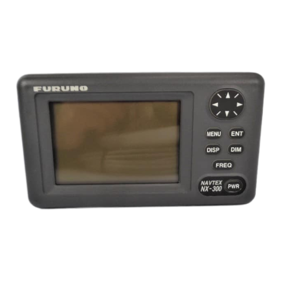
All operation of the NX-300 is carried out with the controls on the front panel of the display unit. Omnipad • Shifts cursor and display. • Selects items on menus. FURUNO MENU Opens menu or Registers items on menus. MENU DISP message display. -
Page 20: Adjusting Dimmer And Contrast
Adjusting Dimmer and Contrast 1. Press the [DIM] key to show the dimmer and contrast setting window. Figure 2-4 DIMMER and CONTRAST setting window 2. Press ! or " for best illumination of the control panel and LCD. 3. Press # or $ for best contrast of the LCD. 4. -
Page 21: Selecting Stations
4. Press ! or " to select menu item and press the [ENT] key. For example, select RCV ALARM. Corresponding option menu appears. Figure 2-7 ON/OFF window 5. Press ! or " to select option desired. 6. Press the [ENT] key to resister your selection. 7 Press the [MENU] key once to return to the menu or twice to quit the menu. -
Page 22: Selecting Messages
Press ! or " to select RECEIVE or IGNORE depending on whether you want to select or deselect the station. Press the [ENT] key. Repeat steps b) to e) to select or deselect other stations. Press the [MENU] key or [DISP] key to close the STATION SELECTION menu. Selecting Messages Press the [MENU] key to open the main menu. -
Page 23: Setting Functions (Functions Menu)
Setting Functions (FUNCTIONS menu) See menu description below for detailed information. Press the [MENU] key to open the main menu. Press ! or " to select FUNCTIONS. Press the [ENT] key to display the FUNCTIONS menu. Figure 2-14 FUNCTIONS menu Press ! or "... - Page 24 SCROLLING: This menu item lets you select how to scroll the message display. The default setting is AUTO-SLOW. AUTO-SLOW: Long press of ! or " scrolls line-by-line slowly automatically. Touch and release " to scroll manually. AUTO-FAST: Long press of ! or " scrolls line-by-line automatically, faster than AUTO- SLOW.
- Page 25 Setting for communication software on PC Baud Rate: 4800 bps Character Length: 8 bit Stop Bit: 1 bit Parity: None X Control: XON/XOFF Downloading messages to a PC Set up the computer to receive data. Messages are downloaded to a PC character by character during reception.
- Page 26 Press the [ENT] key to save. The following messages appear in order. To cancel saving, press the [ENT] key Figure 2-19 SAVING MESSAGES window 10. Press any key to escape. Note1: No message is received during downloading. Note2: When a PC or a serial printer is connected to the NX-300, received messages are displayed on a PC or printed on a serial printer but not displayed or saved to the NX-300 in the following cases;...
-
Page 27: Selecting Language
2.8 Selecting Language You can select language displayed on the NX-300. Languages are English, French, German, Italian, Spanish, Dutch, Danish, and Portuguese. 1. Press the [MENU] key to open the main menu. 2. Press to select LANGUGE. 3. Press the [ENT] key. The following menu appears. (ENG: English, FRA: French, GER: German, ITA: Italian, SPA: Spanish, DUT: Dutch, DEN: Danish, POR: Portuguese) Figure 2-20 LANGUAGE menu 4. -
Page 28: Sample Messages
2.10 Sample Messages When message is displayed, press ! or " to scroll message and press # or $ to display the other message. When the oldest or newest message is displayed, the beep sounds. ID no. Display indications Start code (sync) Scroll bar Main message Press "... -
Page 29: Displaying Navigation Data
2.11 Displaying Navigation Data With navigation data input the NX-300 can display navigation data, in addition to its primary function. 1. Press the [DISP] key to display the receiving messages log. 2. Press the [DISP] key again to display navigation data. Figure 2-23 Nav data display 3. -
Page 30: Selecting Receive Frequency
2.12 Selecting Receive Frequency 1. Press the [FREQ] key to show the frequency window. (Default setting is 518 kHz) Figure 2-24 Frequency window 2. Press to select receive frequency as appropriate. 3. Press the [ENT] key to close the frequency window. 2-12... -
Page 31: System Menu
3. SYSTEM MENU Units of Measurement When navigational data is fed to the NX-300, you can select units of distance and speed to use. Distance/speed can be displayed in nautical miles/knots, kilometers/kilometers per hour, or miles/ miles per hour. The default setting is nautical miles/knots. Press the [MENU] key to open the main menu. -
Page 32: Time Difference (Using Local Time)
Time Difference (using local time) GPS uses UTC time. If a GPS receiver feeds nav data to the NX-300 and you would rather use local time, enter the time difference (range: -13:30 to +13:30) between local time and UTC time. Press the [MENU] key to open the main menu. -
Page 33: Time Display
3.3 Time Display When navigational data is fed to the NX-300, you may display the time in 12-hour or 24-hour notation. The default setting is 24-hour notation. AM or PM is shown when 12-hour notation is selected. Press the [MENU] key to open the main menu. Press ! or "... -
Page 34: Delete All Messages
Delete All Messages This function deletes all messages NX-300 saves. Press the [MENU] key to open the main menu. Press ! or " to select SYSTEM MENU. Press the [ENT] key to show the SYSTEM MENU. Press " to select DELETE ALL MESSAGES. Press the [ENT] key. - Page 35 Press the [ENT] key to show the USER DISPLAY menu. The cursor is now on the LARGE field. LARGE means the center indication on the nav data display. Figure 3-8 USER DISPLAY Press the [ENT] key. The following window appears. Figure 3-9 Options for LARGE window Operate the Omnipad to select item desired.
-
Page 36: Other Functions
4. OTHER FUNCTIONS 4.1 DEMO Mode The DEMO mode provides simulated operation of this unit. Connection of antenna is not necessary. You may select stations and messages manually or automatically and demo messages are received. All controls are operative. Note: Turning on the DEMO mode erases all messages. Press the [PWR] key while pressing to turn the power on. -
Page 37: Changing Received Message Log Window
4.4 Changing Received Message Log Window You can show received frequency on the received message log as shown below. 1. Press the [PWR] key while pressing to turn the power on. 2. Press the [DISP] key to show the received message log. The received frequencies (518 kHz and 490 kHz) are displayed on the window. -
Page 38: Maintenance & Troubleshooting
5. MAINTENANCE & TROUBLESHOOTING WARNING Do not open the equipment. Only qualified personnel should work inside the equipment. Further, watertightness may be reduced. Maintenance Check the following points regularly to maintain performance: • Check that connectors on the rear panel are firmly tightened and free of rust. •... -
Page 39: When The Battery Icon Appears
Press the [ENT] key to start the test. The equipment checks ROM, RAM, SIO and internal battery, and the results are individually displayed as OK or NG (No Good). Program numbers appear at the bottom of the display. Note 1: SIO requires a special connector to check. “03” appears as the result when no connector is connected. -
Page 40: Replacement Of Fuse
If the fuse blows find out the cause before replacing it. If the fuse blows again after replacement, contact a FURUNO agent or dealer for advice. Use only a 1 A fuse – use of a different fuse will damage the equipment and void the warranty. -
Page 41: Installation
6. INSTALLATION Installation of Display Unit Mounting considerations The display unit can be installed on a tabletop, on the overhead, or in a panel (optional flush mounting kit required). Refer to the outline drawings at the end of this manual for installation instructions. -
Page 42: Installation Of Antenna Unit
Installation of Antenna Unit Mounting considerations Install the antenna unit referring to the antenna installation diagram at the end of this manual. When selecting a mounting location for the antenna unit, keep in mind the following points: • Do not shorten the antenna cable (10 m cable fitted to the antenna). •... -
Page 43: Wiring
6.3 Wiring The figure below shows where to connect cables on the rear of the display unit. ANTENNA UNIT NX-3H-D NAVTEX RECEIVER 10 m POWER Ground (12-24 VDC) 1 A FUSE (+ Line) Black To personal computer To navigational equipment Figure 6-3 Wiring Note: The fuse holder contains a spring that fixes the fuse. -
Page 44: Interfacing
GPS navigator GP-31/GP-36 for display on its screen. If you want to connect equipment which outputs data in a format other than RS-232C, a level converter is required for interface. Consult FURUNO dealer for details. Input data sentence description... -
Page 45: Menu Tree
MENU TREE MENU STATION SELECTION MODE ( AUTO , MANUAL) MESSAGE SELECTION ( A-E, L, V: RECEIVE; OTHERS: IGNORE ) Default settings in boldface italic. RCV NOTIFY ( OFF , ON) FUNCTIONS RCV ALARM (OFF, ON ) KEY BEEP (OFF, ON ) ERROR RATE (0-39 33% ) SCROLLING ( AUTO-SLOW , AUTO-FAST, SKIP-$$) -
Page 46: Specifications
SPECIFICATIONS OF THE NAVTEX RECEIVER NX-300 1. RECEIVER UNIT 1.1. Receiving Frequency 518 kHz or 490 kHz 1.2. Mode of Reception 2 µV e.m.f. (50 ohms), 4% error rate 1.3. Sensitivity 1.4. Message Category A: Navigation warning B: Meteorological warning C: Ice report D: Search and rescue information/ piracy and armed robbery E: Meteorological forecast... - Page 47 Data length: 8, Stop bit: 1, Parity: None T/R Code: CR+LF, XON/XOFF Control, Local echo: ON 5. POWER SUPPLY 5.1. NX-300-D + NX-3H-D 12-24 VDC: 130-70 mA 6. ENVIRONMENTAL CONDITION 6.1. Ambient Temperature Antenna unit: -25°C to +70°C Display Unit: -15°C to +55°C 6.2.
-
Page 55: Index
INDEX All clear 4-1 Language menu 2-9 AUTO 1-3 LCD check 5-2 AUTO mode 2-3 Local time 3-2 AUTO-FAST 2-6 AUTO-SLOW 2-6 Main menu 2-2 Maintenance 5-1 BATTERY icon 1-3, 5-2 MANUAL mode 2-3 Message selection 2-4 Mounting 6-1 Contrast 2-2 Control panel 2-1 Navarea 1-1 Navigation data display 2-11, 3-4... - Page 56 SAR 1-3 Saving to PC 2-6 Scroll bar 1-3 SCROLLING 2-6 SKIP-$$ 2-6 Start code 1-2 Station list 1-5 Station map 1-4 Station selection 2-3 SYSTEM MENU 3-1 Termination code 1-2 TEST 5-1 TIME DIFF 3-2 Time difference 3-2 TIME DISP 3-3 Type of message 1-2 Units of measurement 3-1 User display 3-4...