
Related Manuals for Omega CDTX-90 Series


Summary of Contents for Omega CDTX-90 Series
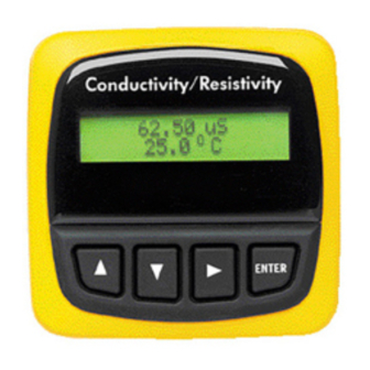
- Page 1 User’ s Guide Conductivity/Resistivity 62.50 uS/cm 25.0°C Shop online at www.omega.com ENTER e-mail: info@omega.com CDTX-90 Series Conductivity/Resistivity Transmitters...
- Page 2 United Kingdom: ISO 9002 Certified It is the policy of OMEGA to comply with all worldwide safety and EMC/EMI regulations that apply. OMEGA is constantly pursuing certification of its products to the European New Approach Directives. OMEGA will add the CE mark to every appropriate device upon certification.
-
Page 3: Installation
1. Installation CDTX-90 Series transmitters are available in two styles: panel mount and field mount. The panel mount is supplied with the necessary hardware to install the transmitter. This manual includes complete panel mounting instructions. Field mounting requires a separate mounting kit. The FP90UM Universal kit enables the transmitter to be installed virtually anywhere. -
Page 4: Electrical Connections
4. Release orange terminal lever to secure wire in place. Gently pull on each wire to ensure a good connection. Wiring Removal Procedure 1. Press the orange terminal lever downward with a small screwdriver to open terminal jaws. 2. When fully open, remove wire from terminal. 3.1 Sensor Connections CDTX-90-1 Terminals CDTX-90-2 Terminals CDTX-90-3 Terminals page 4 Ultra-... - Page 5 Connection to a PLC/Recorder, separate supply Transmitter Terminals Sys. Pwr. Loop - Sys. Pwr. Loop + Power - Power + AUX power required for all CDTX-90 systems. Output - Output + Internal open-collector output circuit 15Ω Isolation Terminals 5-6: Open-collector Output •...
- Page 6 Connection to a PLC/Recorder, separate supply Transmitter Terminals Sys. Pwr. Loop - Sys. Pwr. Loop + Power - Power + AUX required for all CDTX-90 systems. page 6 Relay 2 (NO) Relay 2 (COM) Relay 2 (NC) Relay 1 (NO)
- Page 7 Loop2+ Sys. Pwr. Loop - Sys. Pwr. Loop + Power - Power + AUX power required for all CDTX-90 systems. Output 2- Output 2+ Output 1- Output 1+ Terminals 7-10: Open-collector Outputs •Two transistor outputs, programmable • High or Low setpoint with adjustable hysteresis •...
-
Page 8: Starting Point
Changing the VIEW display does not interrupt system operations. • No key code is necessary to change display selection. • Output settings cannot be edited from the VIEW menu. CDTX-90 Series View Menu Display µ 123.45 +67.89 ºC The VIEW displays below are temporary. The permanent display will return after 10 minutes Loop Output: 13.75 mA... - Page 9 This will recall the last saved value of the item being edited and return you to Step 3. CDTX-90 Series Editing Procedure: Notes on Step 2: If no key is pressed for 5 minutes while display is showing "Enter Key Code", the display will return to the VIEW menu.
- Page 10 In Pulse mode, set the process values where the proportional pulse will start and where it will reach the maximum rate. Be sure to modify this setting if you change the Cond. Units. In Pulse mode, set the maximum rate for the proportional Pulse output. The CDTX-90 will accept any value from 0 to 400.
- Page 11 CDTX-90-1 Options Menu Display (Factory settings shown) Contrast: > Cond Decimal: ****.* > Averaging > Loop Adjust: 4.00 mA > Loop Adjust: 20.00 mA > Temp Display: ºC > Temperature Comp %: 2.00 > Output Active: > Test Loop: >...
- Page 12 CDTX-90-2 Calibrate Menu Display (Factory settings shown) Cell Constant: Standard > Cell: Standard > Cell: Custom 1.0000 > Cond Units: µ > PPM Factor: 2.00 > Set: Temperature > Set: Conductivity > Loop Source: Cond > µ Loop Range: 0.0000 → → → → → 100.000 >...
- Page 13 CDTX-90-2 Options Menu Display (Factory settings shown) Contrast: > Cond Decimal: ****.* > Averaging: > Loop Adjust: 4.00 mA > Loop Adjust: 20.00 mA > Temp Display: ºC > Temperature Comp %: 2.00 > Test Loop: > Test Relay1: >...
- Page 14 CDTX-90-3 Calibrate Menu Display (Factory settings shown) Cell Constant: Standard > Cell: Standard > Cell: Custom 1.0000 > Cond Units: > PPM Factor: 2.00 > Set: Temperature > Set: Conductivity > Loop1 Source: Cond > Loop1 Range: uS 0.0000 → → → → → 100.000 >...
- Page 15 CDTX-90-3 Options Menu Display (Factory settings shown) Contrast: > Cond Decimal: ****.* > Averaging > Loop1 Adjust: 4.00 mA > Loop1 Adjust: 20.00 mA > Temp Display: ºC > Temperature Comp %: 2.00 > Output1 Active: > Test Loop 1: >...
-
Page 16: Calibration Procedure
Calibration Procedure Requirements The CDTX-90 Transmitter is factory calibrated using simulated input signals. System calibration will reduce errors caused by sensor wire lengths longer than the standard 15 ft. length. Wire lengths of 100 feet are acceptable; cable shield must be maintained through cable splice. -
Page 17: Troubleshooting
If a Current Loop is locked at 3.6 mA, the problem is related to the temperature circuit: This occurs only if the CDTX-90 detects a resistance from the temperature sensor that is less than 250Ω or greater than 2800Ω. •... - Page 18 Notes page 18...
- Page 19 Department will issue an Authorized Return (AR) number immediately upon phone or written request. Upon examination by OMEGA, if the unit is found to be defective, it will be repaired or replaced at no charge. OMEGA’s WARRANTY does not apply to defects resulting from any action of the purchaser, including but not limited to mishandling, improper interfacing, operation outside of design limits, improper repair, or unauthorized modification.
-
Page 20: Data Acquisition
Where Do I Find Everything I Need for Process Measurement and Control? Shop online at www.omega.com TEMPERATURE Thermocouple, RTD & Thermistor Probes, Connectors, Panels & Assemblies Wire: Thermocouple, RTD & Thermistor Calibrators & Ice Point References Recorders, Controllers & Process Monitors...