
Related Manuals for Omega DRST-UR


Summary of Contents for Omega DRST-UR
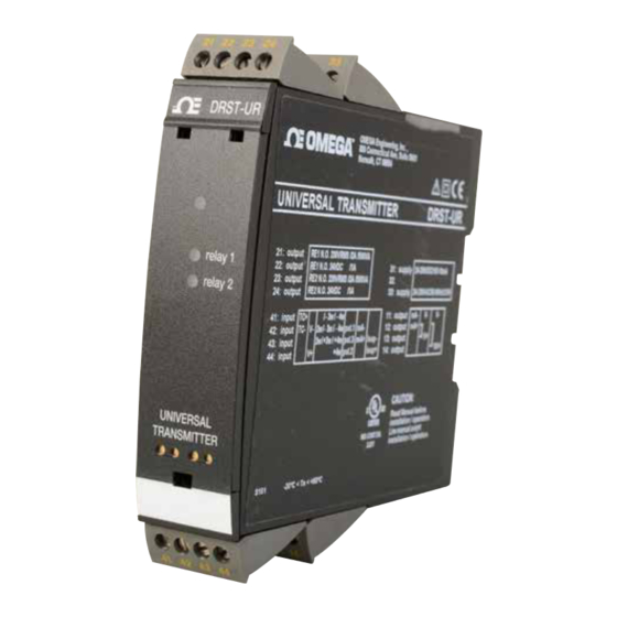
- Page 1 User’s Guide Shop online at omega.com e-mail: info@omega.com For latest product manuals: www.omegamanual.info DRST-UR Universal Transmitter with Relays...
- Page 2 Fax: (203) 359-7700 e-mail: info@omega.com For Other Locations Visit omega.com/worldwide The information contained in this document is believed to be correct, but OMEGA accepts no liability for any errors it contains, and reserves the right to alter specifications without notice.
-
Page 3: Table Of Contents
Section 1 Warning ..................5 Section 2 Symbol Identification ..............6 Section 2.2 Safety Instructions ............6 Section 3 How to dismantle DRST-UR ............8 Section 3.2 Front LED lights red/display shows AO.ER ..8 Section 4 Features ................... 9 Section 4.1 Universal Transmitter DRST-UR ...... - Page 4 Table of DRST-UR Contents Table of Contents Section ................ Page Section 15 Latch ....................23 Section 15.1 Manual deactivation of the latch ......24 Section 15.2 Advanced functions ..........24 Section 15.3 Display setup ............24 Section 15.4 Two-point process calibration ....... 24 Section 15.5 Process simulation function ........
-
Page 5: Section 1 Warning
SYSTEM 4000 must be mounted on a DIN rail according to DIN 46277. INSTALLATION WARNING Do not open the front plate of the device as this will cause damage to the connector for the display/programming front Omega DRSL-DISPLAY. This device contains no DIP-switches or jumpers. -
Page 6: Section 2 Symbol Identification
Symbol Identification Section 2.1 - Symbol Identification Triangle with an exclamation mark: Warning/demand. Potentially lethal situations. The CE mark proves the compliance of the device with the essential requirements of the directives. The double insulation symbol shows that the device is protected by double or reinforced insulation. - Page 7 Safety Instructions Mounting and connection of the device should comply with national legislation for mounting of electric materials, i.e. wire cross section, protective fuse, and location. Descriptions of input / output and supply connections are shown in the block diagram and side label. The following apply to fixed hazardous voltages-connected devices: The max.
-
Page 8: Section 3 How To Dismantle Drst-Ur
Section 3.2 - When front LED lights red / display shows AO.ER Omega DRST-UR is designed as a SIL 2 device with a high safety level. Therefore, a continuous measurement of the outgoing current is carried out on a 4...20 mA and 20...4 mA output signal. If the current output signal is different from the internal calculated output value or the current output is 0 (due to e.g. -
Page 9: Section 4 Features
• Process control with 2 pairs of potential-free relay contacts and analogue output. • Galvanic separation of analogue signals and measurement of floating signals. • The DRST-UR is designed according to strict safety requirements and is thus suit able for application in SIL 2 installations. -
Page 10: Section 5 Display Characteristics
Section 5.2 - Application • Communications interface for modification of operational parameters in DRST-UR. • Can be moved from one DRST-UR device to another and download the configuration of the first transmitter to subsequent transmitters. • Fixed display for readout of process data and status. -
Page 11: Section 6 Mounting / Demounting
Mounting / Demounting the DRSL-DISPLAY/DRST-UR 1: Insert the taps of DRSL-DISPLAY/DRST-CM into the holes at the top of the device. 2: Swing DRSL-DISPLAY/DRST-CM into place. Demounting of DRSL-DISPLAY/DRST-UR 3: Push the release button on the bottom of DRSL-DISPLAY/DRST-UR and swing DRSL-DISPLAY/DRST-UR up. -
Page 12: Section 7 Inputs Application
Inputs Application Input signals: Volt -age Potentio meter Current RTD and lin.R Connect., wires Order separately: 5910 CJC connector. See the connection drawing on page 16. Output signals: Relays 10 V 10 V Analogue, 0/4...20 mA and voltage Supply: 21.6...253 VAC 19.2...300 VDC... -
Page 13: Section 8 Order Codes / Specifications
Order codes / Specifications Order codes DRST-UR = Universal transmitter DRSL-DISPLAY = Display/programming front 5910 = CJC connector Electrical specifications Environmental conditions Specifications range ....... -20°C to +60°C Calibration temperature ....20...28°C Relative humidity ......< 95% RH (non-cond.) Protection degree ......IP20 Mechanical specifications Dimensions (HxBxD)...... -
Page 14: Section 8 Order Codes / Specifications
Order codes / Specifications Section 8 - Inputs Basic values Input Basic Temperature type accuracy coefficient ≤ ±4 µA ≤ ±0.4 µA / °C Volt ≤ ±20 µV ≤ ±2 µV / °C Pt100 ≤ ±0.2°C ≤ ±0.01°C / °C Linear resistance ≤... - Page 15 Order codes / Specifications Section 8.2 - TC Input Min. Max. Type value value Standard 0°C +1820°C IEC 60584-1 -100°C +1000°C IEC 60584-1 -100°C +1200°C IEC 60584-1 -180°C +1372°C IEC 60584-1 -200°C +900°C DIN 43710 -180°C +1300°C IEC 60584-1 -50°C +1760°C IEC 60584-1 -50°C...
- Page 16 Order codes / Specifications Current output Signal range (span) ......0...20 mA Programmable signal ranges ..0...20 / 4...20 / 20...0 and 20...4 mA Load (max.) ........20 mA / 800 Ω / 16 VDC Load stability ........≤ 0.01% of span / 100 Ω Sensor error detection ....
-
Page 17: Section 9 Visualisation In The Drsl-Display Of Sensor Error Detection
Sensor error check: Device: Configuration Sensor error detection: R1, ERR.ACT=NONE - R2, ERR. ACT=NONE, DRST-UR OUT.ERR=NONE. Else: Outside range readout (IN.LO, IN.HI): If the valid range of the A/D converter or the polynomial is exceeded Input Range... -
Page 18: Section 10 Error Indications
Check that saved configuration in DRSL-DISPLAY matches device TY.ER Configuration is not DRST-UR ! Error indications in the display flash once per second. The help text explains the error. 1) The error is reset by switching off and then switching on the supply voltage to the device. -
Page 19: Section 11 Connections
Connections Section 11 - Connections Supply: Inputs: TC, internal CJC sensor RTD, 2-wire RTD, 3- / 4-wire Resistance, 2-wire Resistance, Potentiometer 2-wire transmitter Current 3- / 4-wire *TC, CJC connector Voltage * Order separately: CJC connector 5910 Outputs: Current Voltage, 1 V Voltage, 10 V Relays... -
Page 20: Section 12 Block Diagram
V loop Supply A / D D / A 10 V Ω 50 W Green Ω EEPROM I + V Out. Out. Out. 50.0 l / min Relay 2 VALVE 5 Yellow Relay 2 Relay 1 DRST-UR Yellow Relay 1... -
Page 21: Section 13 Configuration / Operating The Function Keys
In general When configuring the DRST-UR, you will be guided through all parameters and you can choose the settings which fit the application. For each menu there is a scrolling help text which is automatically shown in line 3 on the display. -
Page 22: Section 14 Signal & Sensor Error Display
Signal & sensor error display Section 13.1 - Signal and sensor error info via display front DRSL-DISPLAY Sensor error (see limits in the table) is displayed as SE.BR (sensor break) or SE.SH (sensor short). Signals outside the selected range (not sensor error, see table for limits) are displayed as IN.LO indicating low input signal or IN.HI indicating high input signal. -
Page 23: Section 15 Latch
Latch Latch When the setpoint is exceeded the relay outputs enters an alarm state. The latch function of the DRST-UR will hold the relays in this state until the function is deactivated manually. The latch function can be applied when the relay function setpoint or window is selected. -
Page 24: Section 15.1 Manual Deactivation Of The Latch
Latch Section 15.1 - Manual deactivation of the latch function If the relay outputs are activated and thereby latched, it will be indicated in the display. The backlight flashes and the scrolling help text tells you how to deactivate the output. Manual deactivation is carried out by way of the front buttons on the DRSL-DISPLAY. -
Page 25: Section 16 Auto Diagnosis
Auto Diagnosis Section 16 - Auto diagnosis The device performs an advanced auto diagnosis of the internal circuits. The following possible errors can by displayed in the front unit DRSL-DISPLAY. CJ.ER - CJC sensor defect or CJC temperature outside range FL.ER - Flash error AO.ER -... -
Page 26: Section 17 Units/Safety/Memory
Units/Safety/Memory Section 17.1 - Selection of units After choosing the input signal type you can choose which process units should be displayed in text line 2 (see table). By selection of temperature input the process value is always displayed in Celsius or Fahrenheit. This is selected in the menu point after selection of temperature input. -
Page 27: Section 18 Routing Diagram
Routing Diagram Power up Fast setpoint adjustment 50.0 and relay test RELAY1 Increase setpoint Txt 57 Decrease setpoint 75.0 Save and exit the menu simultaneously = change relay state RELAY2 50.0 Txt 57 12.0 2-10 VOLT 0-10 CURR 1111 POTM 111.1 LIN.R 0.2-1... -
Page 28: Section 18 Routing Diagram
Routing Diagram Section 18.1 - Routing diagram If no key is activated for 1 minute, the display will return to the default state 1.0 without saving configuration changes. Increase value / choose next parameter Decrease value / choose previous parameter Accept the chosen value and proceed to the next menu Hold Back to previous menu / return to menu 1.0 without saving... - Page 29 Routing Diagram SETP WIND HOLD CLOS OPEN INCR 3600 3600 N.O. 100.0 100.0 NONE DECR 0000 0000 N.C. NONE SETP N.O. 50.0 INCR ERR.ACT ON.DEL OFF.DEL R2.FUNC R2.CONT R2.SETP ACT.DIR R2.HYST Txt 24 Txt 25 Txt 26 Txt 19 Txt 20 Txt 21 Txt 22 Txt 23...
- Page 30 Routing Diagram S20-4 20-4 20-0 S4-20 HOLD 4-20 CLOS 0-20 23mA OPEN 0/3.5mA 3600 3600 VOLT NONE NONE 0000 0000 CURR -200 -200 NONE CURR 4-20 23mA 150.0 ERR.ACT ON.DEL OFF.DEL ANA.OUT O.RANGE OUT.ERR OUT.LO OUT.HI Txt 24 Txt 25 Txt 26 Txt 36 Txt 37...
-
Page 31: Section 18.2 Advanced Settings
Routing Diagram Section 18.2 - Advanced settings (Routing diagram) Advanced settings (ADV.SET) 2.0 In the submenu simulation (SIM) you must press to return to the default state 1.0. DISP PASS LANG SAVE LOAD SAVE SETUP MEMORY Txt 43 Txt 44 A.OUT DISP A.OUT... -
Page 32: Section 18.1 Routing Diagram
Routing Diagram Section 18.3 - Manual deactivation (Routing diagram) Manual deactivation of the latch function To setup menu 40.0 Rx.LATC ENT.SET Txt 67 Txt 65 0000 9999 R1 reset 40.0 0000 40.0 To default state 1.0 R1.LATC R1.LATC PASSW R1.RLSE Txt 65 Txt 65 Txt 1... -
Page 33: Section 19 Scrolling Help Text In Display
Select WINDOW function - relay controlled by 2 Enter relay latch setup Select voltage input setpoints [44] Load saved configuration into DRST-UR [04] Select 0.0-1 V input range Select SETPOINT function - relay controlled by 1 Select 0.2-1 V input range... -
Page 34: Section 20 Graphic Depication Of Latch
Graphic Depication of Latch Section 20.1 - Graphic depiction of latch function setpoint Input signal ON delay OFF delay Setpoint (increasing) Hysteresis Time Relay latched Closed Relay contact (N.O.) Open Release not possible (setpoint still exceeded) Release not possible (setpoint-hysteresis still exceeded) Release not possible (OFF delay still exceeded) Release possible (manual deactivation) -
Page 35: Section 20.1 Latch Function Setpoint
Graphic Depication of Latch Section 20.2 - Graphic depiction of latch function window ON delay OFF- delay ON delay OFF delay Hysteresis Setpoint high Window Setpoint low Hysteresis Time Relay latched Relay latched Closed Relay contact (N.O.) Open Release not possible (still inside window) Release not possible (inside hysteresis) Release not possible (OFF delay still active) Release possible... -
Page 36: Section 20.3 Relay Action Setpoint
Graphic Depication of Latch Section 20.3 - Graphic of relay action setpoint Relay units Relay units Hysteresis = 10 Setpoint = 50 Setpoint = 50 Hysteresis = 10 Off N.O. On N.O. Off N.O. Off N.O. On N.O. Off N.O. On N.C. -
Page 37: Section 21 Displays
Displays Section 21.1 - Displays Programmable displays with a wide selection of inputs and outputs for display of temperature, volume and weight, etc. Feature linearization, scaling, and difference measurement functions for programming via PReset software. 21.2 - EX Interfaces Interfaces for analog and digital signals as well as ®... -
Page 38: Section 21 Displays
Displays 21.4 - Temperature A wide selection of transmitters for DIN form B mounting and DIN rail devices with analog and digital bus communication ranging from application- specific to universal transmitters. 21.5 - Universal PC or front programmable devices with universal options for input, output and supply. - Page 39 Department will issue an Authorized Return (AR) number immediately upon phone or written request. Upon examination by OMEGA, if the unit is found to be defective, it will be repaired or replaced at no charge. OMEGA’s WARRANTY does not apply to defects resulting from any action of the purchaser, including but not limited to mishandling, improper interfacing, operation outside of design limits, improper repair, or unauthorized modification.
- Page 40 Where Do I Find Everything I Need for Process Measurement and Control? OMEGA…Of Course! Shop online at omega.com TEMPERATURE M U Thermocouple, RTD & Thermistor Probes, Connectors, Panels & Assemblies M U Wire: Thermocouple, RTD & Thermistor M U Calibrators & Ice Point References M U Recorders, Controllers &...