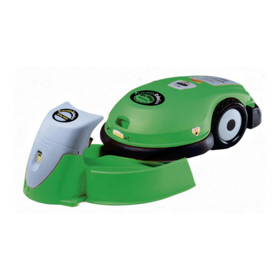
Friendly Robotics robomower RL1000 Operation Manual
W/ charging station
Hide thumbs
Also See for robomower RL1000:
- Service manual (213 pages) ,
- Operating & safety manual (20 pages)

Related Manuals for Friendly Robotics robomower RL1000


Summary of Contents for Friendly Robotics robomower RL1000
- Page 1 Operating & Safety Manual RL1000 & Charging Station www.friendlyrobotics.com DOC0076B...
-
Page 2: Ec Declaration Of Conformity
7. Technical documentation kept by Mr. Dedy Gur, QA director. I hereby declare that the above product conforms to the requirements as specified above. *The original RL500 was tested by BSI in 2000. All Friendly Robotics models currently sold were tested by F.Robotics Acquisitions Ltd. - Page 3 The products are manufactured by F. Robotics Acquisitions (Friendly Robotics). © Friendly Robotics, 2006-A. All rights reserved. No part of this document may be photocopied, reproduced, electronically or translated without the prior written consent of Friendly Robotics. Product, product specifications and this document are subject to change without notice. All other trademarks are property of their respective owners.
-
Page 4: Table Of Contents
Table of Contents Safety Warnings & Precautions ………………………………………….….……… 5 Safety Features …………………………………………………………….….…..…. 8 What’s in the Box …………………………………………………………………..10 Chapter 1 – Charging Station & Perimeter Wire Setup…………………..….….. 12 ® Chapter 2 – Preparing the RoboMower …………………………………………. 29 Chapter 3 – Manual & Automatic Operation…………………………………….…37 Chapter 4 –... -
Page 5: Safety Warnings & Precautions
Safety Warnings & Precautions Training and Instructions ® Read this manual carefully before operating RoboMower . Be familiar with the controls and ® the proper use of RoboMower and follow all safety and warning instructions. ® Do not use RoboMower for any purpose other than for which it is intended. - Page 6 ® Do not start RoboMower operation in automatic mode outside the plot bounded by the perimeter wire. Charging Station Never let RoboMower operate without supervision. When programming the automatic departure times and days, insure these windows of operation are programmed when children, pets and other bystanders are not on the lawn.
- Page 7 Safety Warnings & Precautions Warning Decal Definitions 1. WARNING-this is a dangerous power tool. Use care when operating and follow all safety instructions and warnings. 2. Read the owner/operating manual carefully and follow all safety instructions. 3. Objects can be thrown from mower while operating, take caution. 4.
-
Page 8: Safety Features
® RoboMower - Safety Features 1. Child Guard / Safety Guard This menu option offers a safety feature to help prevent children or others not familiar with the safe operation of the mower to operate it freely. 2. Lift Sensor There is a sensor located on the front caster wheel of the mower. - Page 9 11. Over-Current Monitoring Protection Each of the three blade motors and each of the two wheel drive motors are monitored continuously during operation for any situation that may cause these motors to over-heat. In such event, the RoboMower will stop operation of at least that motor and possibly the mower itself and indicate that the motor is cooling down.
-
Page 10: What's In The Box
What’s in the Box ® (RoboMower ® 1. RoboMower 2. Power Pack 3. Operating & Safety Manual 4. RoboRuler Used for setting the distance of the perimeter wire from the lawn edge. 5. Pegs Used for securing the perimeter wire to the ground around the lawn perimeter and around obstacles. -
Page 11: Charging Station
What’s in the Box (Charging Station) 9. Base Used for directing the RoboMower to the charging contacts. 10. Cover including the Perimeter Switch & a Power Supply Used for recharging the RoboMower Power Pack and activates the perimeter wire, which defines the area in which the RoboMower will operate. -
Page 12: Chapter 1 – Charging Station & Perimeter Wire Setup
Chapter 1 Charging Station & Perimeter Wire Setup Cover Base CAUTION! Refer to the specific safety instructions related Screw (x2) Stake (x5) with operation of the RoboMower with a Charging Station, as specified in the Fence Safety chapter. Drive wheel supports Screw (x2) Figure 1.1 Charging Station Assembly 1.1 Charging Station Zone... - Page 13 Note: The power supply is suitable for outdoor use, yet it is required placing it in a sheltered place, dry location, which is well ventilated and not exposed to direct sunlight. It is recommended to place the Charging Station as close as possible to a receptacle, roll the extra cable and store it near the power supply.
- Page 14 • A minimum distance of 8 feet (2.5 meters) is required between the Charging Station fence and the perimeter island. See figure 1.5. Greater than 8 feet (2.5m) Figure 1.5 – Distance From Perimeter Island Place the Charging Station on level ground. Do not place the Charging Station on a slopping ground. See figure 1.6.
- Page 15 • The RoboMower is impervious to water and rain, however it is recommended to place the Charging Station away from sprinkler heads for maximum protection. See figure 1.7 Figure 1.7 – Avoid Placement Near Water Sprinklers Now, knowing the location of the Charging Station, you can begin to setup the Perimeter Wire in the Charging zone.
- Page 16 WARNING! Damage to the eye is possible. Use proper eye protection and wear appropriate work gloves when hammering the pegs. Hard or dry ground may cause pegs to break when driving them in. In extreme cases, watering the lawn where the pegs will be driven can be beneficial.
- Page 17 Add pegs in to pull the perimeter wire down to the ground surface, below the Perimeter Wire grass tips. Tip! It is recommended to water the ground prior to pegging the wire. Figure 1.10 – Pegging the Perimeter Wire 1.6 Corners & Sharp Turns Care must be taken not to create a corner sharper than 90 degrees when setting up the perimeter wire.
- Page 18 1.8 Defining Obstacles-Perimeter Islands Many obstacles can be left in the lawn without consideration to excluding them using the perimeter wire. The basic rule of thumb is that the obstacle must be at least 6 inches (15 cm) high from the ground and the obstacle must be relatively rigid.
- Page 19 Figure 1.13 – Perimeter Wire Setup Distances for Obstacles Tree too close to perimeter, less than 4 Trees large enough to allow Small tree, must feet (1.2m), loop out with RoboMower to bump into do not exclude with perimeter perimeter wire require a perimeter wire around it wire Minimum distance...
- Page 20 1.9 Multiple Zones/Areas As mentioned earlier, your home may require more than one zone to be set up in order for the RoboMower to work in all of your lawn effectively. Having two or even three zones does not affect the efficiency of the RoboMower and in many circumstances is more desirable than one large zone.
- Page 21 1.10 Slopes As a general rule of thumb, any slope that can safely be cut using a walk behind mower can also be cut using the RoboMower in the automatic mode. The maximum slope limit is 15 degrees, the same as a traditional walk behind mower.
- Page 22 1.12 Assemble Power Supply Cord to Charging Board Before securing the power cord to the Charging Station, carefully lay the length of the cord out, beginning from the Charging Station and leading to the main power supply to insure that the Charging Station is placed close enough to the main power for the supply cord to reach.
- Page 23 Carefully align the three slots on the fence with the three tabs on the base. See figure 1.23. Once aligned, push the fence firmly down onto the base until it has snapped into place. Base Fence Figure 1.23 – Fence Alignment Align the left wheel support with the Charging Station Base as shown in Figure 1.24a.
- Page 24 1.14 Placing and testing the Charging Station • Use the RoboRuler to place the Charging Station on the perimeter. The shorter distance (12 inches / 30 cm) is used where the area outside the immediate perimeter of the Charging Station is free of obstacles and is the same relative height as the perimeter edge (See Figure 1.25).
- Page 25 Test the Charging Station setup. Connect the power supply to a regular household receptacle 120 Volts AC (models outside the US use a 230 volt main power). Press the ‘On’ button on the Charging Station Operation Panel. A small flashing green light next to the ‘On’ button indicates the system is on and functioning correctly.
- Page 26 Setup in Non-Charging Zone Note: Setup in a non-Charging zone requires a Perimeter Switch (available as an accessory - see Chapter 10 - Accessories). 1.16 Perimeter Switch Placement and Perimeter Wire Setup Find a convenient spot outside the perimeter of the non-Charging zone, but a location that is relatively easy for you to access.
- Page 27 Take the Perimeter Switch and squeeze the tabs on both sides of the Perimeter Switch as shown in figure 1.31, and remove the back cover from the Perimeter Switch. Insert the 3 C-cell batteries in the battery holder as shown in Figure 1.32 and reassemble the Perimeter Switch.
- Page 28 1.19 Placing The Perimeter Switch The Perimeter Switch connector is designed for quick and easy disconnection, a flexible feature, should your lawn require more than one plot. You easily disconnect it by simply pulling the connectors apart. This allows you to easily move the perimeter switch between plots. The Perimeter Switch also comes with a large stake that fastens to the back of the perimeter switch, making movement from one plot to another easier by allowing you to disconnect the switch and move it with the stake still attached.
-
Page 29: Chapter 2 – Preparing The Robomower
Chapter 2 ® Preparing The RoboMower Charging Contact Pins Carrying handle Bumpers with touch sensitive sensors Manual Controller Operating Lamp Power Pack ® Figure 2.1 - A basic ‘what is what’ of the RoboMower 2.1 Inserting Power Pack Fuse Your RoboMower is shipped with the Power Pack fuse removed and it will not operate without it. The fuse is contained in a small plastic bag attached to the top of the Power Pack. - Page 30 2.2 Using The Manual Controller The RoboMower is equipped with a Manual Controller. It enables you to manually drive and operate the mower. To get started on using the Manual Controller, study figure 2.3 to view the various operating controls and their functions. Refer to Chapter 5, Manual Operation for full details regarding use of the Manual Controller.
- Page 31 2.3 Manual and automatic operation The RoboMower is safely designed so that operation in the manual mode is prohibited unless the Manual Controller has been removed from its’ holder and is in the possession of the user to operate the buttons. See Figure 2.4. The manual mode is used to primarily move/drive the RoboMower into the lawn and to return it after mowing.
- Page 32 2.5 Setting The Cutting Height And Ground Clearance Remove the Power Pack before making any adjustments. The RoboMower has two basic adjustments, cutting height and ground clearance. When using the high cut blades, the cutting height is adjustable from approximately 1.5 inches to 3.5 inches (3.8 cm – 8.9 cm) and with the low cut blades from 1 inch to 2.5 inches (2.5 cm –...
- Page 33 2.6 Set Country and Perform One Time Calibration The RoboMower uses a sophisticated navigation system that utilizes an on-board compass type device, which responds to the magnetic poles of the earth. Magnetic North can vary from one point on the earth to another, based on geography. In order to accommodate this variance, it is necessary to calibrate the compass device to the area of the earth where the mower is being used.
- Page 34 Figure 2.10 – Calibrating Sequence LCD Display Action Required Dock Zone Dock Zone GO’ Press ‘ Press GO Press GO GO’ Press ‘ Set Country Set Country Press GO Press GO Scroll up or down to Not Set! Not Set! find your country Scroll Scroll...
- Page 35 2.7 Testing the Charging Station and Perimeter Wire Position for Charging It is best to test the position of the Charging Station and to determine if any small adjustments need to be made before driving the rest of the stakes into place. Position the RoboMower towards the perimeter wire, at least 10 feet (3m) before the Charging Station to allow the mower to stabilize itself on the wire.
- Page 36 Position the RoboMower towards the wire, after the Charging station Figure 2.12 – Testing the Perimeter Wire Position Press the upper scroll arrow once for the ‘Go to dock’ option and press ‘GO’. Walk along the side of the RoboMower while it is following the edge. At any point where the mower position is too far to the outer edge of the lawn area, note this area and slightly move the wire towards the interior.
-
Page 37: Chapter 3 – Manual & Automatic Operation
Chapter 3 Manual and Automatic Operation 3.1 Activating The Perimeter Switch – Charging Zone Area/zone with Charging Station If the RoboMower is operated from the Charging Station in automatic or manual-depart (see paragraphs 3.2 and 3.3), the RoboMower will automatically switch the Perimeter Switch at the Charging Station Control Panel on and off to coincide with depart and dock events. - Page 38 - Confirm the Perimeter Switch is turned on and the mower is pointed at any perimeter wire section (not an island or excluded obstacle). Press the upper scroll arrow once for the ‘Go to dock’ message option to display and then press GO.
- Page 39 Chapter 3 Page 28 Edge Mowing – Non-Charging Zone Important! When mowing in non-Charging zone, it is required first to define the non-Charging zone (Refer to section 6.2.1.1 ‘Work time’). Insert the Manual Controller into its holder and press the ‘Down’...
- Page 40 Skipping Edge Mowing The RoboMower provides a means that will allow you to skip the edge mowing process and start directly with the scanning (mowing) process. In order to do this, simply press the ‘GO’ button two times at the initial startup of the mower. Pressing ‘GO’ the second time immediately following the first press will tell the mower to skip mowing the edge.
- Page 41 The Manual Controller can only operate in manual mode when removed from the holder, which holds it in place during automatic operation. For safety it is designed in such a way that manual operation is prohibited while in the holder and automatic operation is prohibited when removed from the holder. You will also notice that the Manual Controller contains the keypad for starting automatic operation as well as the emergency stop.
-
Page 43: Chapter 4 – Setting The Weekly Program
Chapter 4 Setting the Weekly Program 4.1 Setting the Time The first step before setting the weekly program is to set the current time: day of the week and clock. Note that the clock is on a 24hour military time scale. There are two options to set the time. - Page 44 4.2 Setting the Weekly Program Remove the Manual Controller and follow the steps as outlined below: (For a shortcut to the weekly program setting, refer to paragraph 4.4 – section 2). Manual Manual Press ‘GO’ Press ‘GO’ User Options User Options User Preferences User Preferences Scroll up or down until the...
- Page 45 Note: The clock resets itself each time the Power Pack is removed; ‘Set time’ message will then display: Set Time Press GO WARNING! Never let RoboMower operate without supervision. Serious injury can occur. If the current date and time are not set correctly or are failed to be set when prompted, the times scheduled for automatic departure will not be correct.
- Page 46 2. RoboMower is in the Charging Station - press the up scroll arrow once – the weekly program is displayed for 10 seconds: This screen will display for 10 M T W T F S S seconds and then disappear. - - + (+ means active day) Pressing the ‘GO’...
-
Page 47: Chapter 5 – Charging
Chapter 5 Charging 5.1 Charging Of all the areas regarding the RoboMower, proper charging of the Power Pack is second only to safety in importance. Failure to follow the charging guidelines will result in poor performance and a short Power Pack life. - Page 48 5.3 Charging Using the Indoor Power Supply Connected to the Charging Socket If the need arises, the Power Pack may be re-charged using the indoor Power Supply (available as an accessory) and connecting it to the charging socket on the Manual Controller holder. This is designed ONLY for indoor use and should never be used to charge the RoboMower while still docked in the Charging Station.
- Page 49 Charging is such an important aspect for assuring good performance and Power Pack life that a special alert and power management system is incorporated into the mower to remind and alert you when the proper charging process is not occurring. Ready Charging Keep Charging...
- Page 50 The ‘Recharge Battery’ level has a higher priority in the power management system than ‘Time Completed’ for the obvious reason that the Power Pack voltage is at a lower level. For this reason, immediately following a ‘Recharge Battery’ message the RoboMower will emit a buzzer sound every 30 seconds for the next 20 minutes in order to alert you that the mowing session is completed and it is now time to re-connect the Power Supply to the RoboMower.
-
Page 51: Chapter 6 – Settings And Advanced Features
Chapter 6 Settings and Advanced Features 6.1 User Options Lifting the Manual Controller from its holder will change the text display on the LCD to the manual operating menu, as seen in Figure 6.1. Manual Figure 6.1 User options Pressing ‘GO’ once will take you to the next screen, ‘User Preferences’. Figure 6.2. Using the ‘Up ⇑... - Page 52 6.2 User Preferences Press ‘GO’ to view the menu of user preferences, beginning with ‘Zones setup’, Figure 6.3. Using the ‘Up ⇑ Down ⇓’ arrow keys will allow you to scroll through these menu items. Pressing ‘GO’ will take you to these various preferences. Figure 6.3. User Preferences User Preferences User Preferences...
- Page 53 6.2.1.1 Work Time Allows the user the option of setting the operating time from the ‘MAX’ default setting to times ranging from 20 minutes up to 2:40 hours. Figure 6.5. This option is available for up to 4 different zones, Dock Zone, Zone B, C or D. Having four different zones can allow you to set operating time for several different zones that are of varying sizes, not requiring the same operating time for mowing.
- Page 54 6.2.1.3 Set Default Edge Selecting Default Edge restores the factory default edge distance to the specific zone selected. 6.2.2 Sound Allows user to shut off non-safety related operating sounds. 6.2.3 Wire position Allows user to test the wire position in ‘Edge’ mode while the mowing motors are switched off to prevent any damage to the perimeter wire after the initial setup of the wire is completed.
- Page 55 Anti theft Anti theft Press GO Press GO Anti theft Anti theft Press GO Press GO Press GO Press GO Change password Change password Press GO Press GO Figure 6.7 6.3 Information Pressing ‘GO’ at the ‘Information’ display will open the option to scroll between the following menus (Figure 6.8): Total time Total time...
- Page 56 6.4 Docking Options (for Charging Station only) Pressing ‘GO’ at the ‘Docking options’ display will open the option to scroll between the following menus (Figure 6.9): Press ‘GO’ Press ‘GO’ Docking options Docking options Weekly program Weekly program Press GO Press GO Press GO Press GO...
- Page 57 One of the following displays is appeared One of the following displays is appeared when the mower is in the Docking Station when the mower is in the Docking Station Press the down Press the down Press the down Press the down 11:28 11:28 11:28...
- Page 58 Never use the RoboMower with a safety device or feature not properly operating. Never attempt to disable or bypass any safety device or system. See an authorized Friendly Robotics service facility for repair or information regarding any safety system or device.
-
Page 59: Chapter 7 – Text Messages And Troubleshooting
Chapter 7 Text Messages and Troubleshooting 7.1 Messaging The RoboMower is equipped with a sophisticated monitoring system that will notify you in the form of a text message in the LCD panel when common operational faults occur. In addition, it will also communicate in text form several messages that are meant as a prompt to the user to perform a certain function or action. - Page 60 Message Probable Cause/Event Corrective/User Action Displayed - Make sure that both mower drive wheels are - The mower contacts do not touch the Docking leveled with the Docking Station base (if Station contacts necessary fill the area underneath the drive wheels with dirt) - Clean the contacts with a brush or piece of - The mower or Docking Station contacts are dirty...
- Page 61 Message Probable Cause/Event Corrective/User Action Displayed - Mower is searching for the Charging Station but the - Drive the mower manually for charging in the Low battery battery voltage is too low to continue the searching Charging Station process - RoboMower charging is not allowed when the - RoboMower is charged through the plug and ambience temperature is going down below Low temp.
- Page 62 Message Probable Cause/Event Corrective/User Action Displayed - Confirm there is enough time between the two Skipped: Low - RoboMower has skipped the last depart due to low adjacent departures so the battery can be battery voltage charged prior the scheduled operation (min 16 hours between operations) Skipped: Rain - It is not recommended to cut wet or damp...
- Page 63 Problem Encountered Probable Cause/Event Corrective/User Action - Check for power to this main receptacle by plugging in another appliance. - Turn power on to the main receptacle. RoboMower does not detect - Disassemble the Charging Station Cover by the Charging Station contacts unscrewing the screws and check the - No power to receptacle or main and/or ‘Front wheel problem’...
- Page 64 Problem Encountered Probable Cause/Event Corrective/User Action - Batteries are completely - Install fresh alkaline C-cell batteries discharged. - Batteries installed with wrong - Verify correct placement of batteries. Perimeter Switch will not polarity position. activate when turned on. - Water/moisture protection of the Perimeter - Perimeter Switch not installed Switch can only be insured when mounted vertically and exposed to water/rain.
- Page 65 Problem Encountered Probable Cause/Event Corrective/User Action Raise ground clearance to the Low ground clearance. uppermost position. The RoboMower gets stuck Cutting height too low. Raise cutting height frequently when traveling over Fill in all holes, cover or exclude all less than optimal terrain. Terrain needs landscaping repairs.
-
Page 66: Chapter 8 – Specifications
Chapter 8 Specifications Bottom Dimensions 89cm l x 66.5cm w x 31.5cm h (35” x 26” x 12.5”) Weight 22.6kg (50lb.) Unit + 12.6kg (28lb.) Power Pack Front Noise level < 85 db (A) Mowing Width 3 Blades and a total cutting width of 53cm (21”) Cuts 1.5cm outside the wheels Mowing Height 6 settings at the front and 2 at the rear... -
Page 67: Maintenance And Storage
Chapter 9 Maintenance and Storage Recommended Maintenance Schedule Maintenance Service Maintenance Procedure Interval Check and remove grass clippings and dirt from the mowing deck if necessary, particularly when mowing wet and damp grass (refer to section 9.1) Each Use Charge the Power Pack after every use. 50 Hours Remove Power Pack and check any damage on the blades (refer to section 9.2) Replace the blades;... - Page 68 Whenever replacing the blades, it is recommended to restart the counter of the blades replacement reminder by choosing the ‘Blades replaced’ option under the ‘User Preferences’ menu and press the GO button again to clear the reminder. Figure 9.1 Squeeze tabs & pull Squeeze tabs &...
- Page 69 9.4 Power Pack Always follow the maintenance and charging instructions found in Chapter 5 for the Power Pack. 9.5 Disposing of the Old Battery Pack Important! Do not place used batteries in your household trash. The battery must be collected, recycled, or disposed of in an environmentally sound manner.
- Page 70 You may place the Friendly Robotics wire nut connector onto each end of this cord for protection in the winter. If this or a similar weather resistant connector is not used, oxidation may occur. Do not forget to disconnect the perimeter wire ends from the plot connector and protect the ends of these wires in a similar way as the power supply leads.
-
Page 71: Chapter 10 – Accessories
Chapter 10 Accessories Perimeter Switch Convenience of having a switch for each zone and not moving one switch from zone to zone. Peg Pack (50) For larger lawns and additional zones. Perimeter Wire For larger lawns and additional zones. Power Pack Convenience of increasing capacity with a second battery. - Page 72 Friendly Robotics is not liable for indirect, incidental or consequential damages in connection with the use of the Friendly Robotics Product covered by this warranty, including any cost or expense of providing substitute equipment or service during reasonable periods of malfunction or non-use pending completion of repairs under this warranty.
- Page 76 www.friendlyrobotics.com...