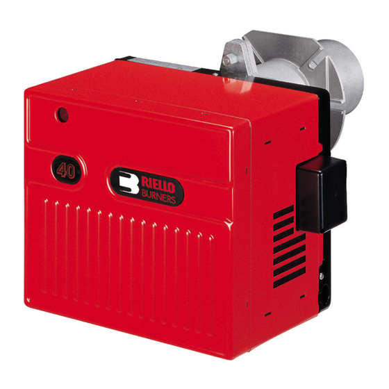
Riello GS10 Installation, Use And Maintenance Instructions
Forced draught gas burner
Hide thumbs
Also See for GS10:
- Installation, use and maintenance instructions (60 pages) ,
- Installation, use and maintenance instructions (32 pages) ,
- Installation, use and maintenance instructions (41 pages)
Table of Contents
Advertisement
Montage und Bedienungsanleitung
Manuel d'entretien
Installation, use and maintenance instructions
Instrucciones para la instalación, uso y mantenimiento
Gas-Gebläsebrenner
D
Brûleur gaz à air soufflé
F
Forced draught gas burner
GB
Quemador de gas de aire soplado
E
Einstufiger Betrieb
Fonctionnement à 1 allure
One stage operation
Funcionamiento de una llama
CODE - CÓDIGO
3755426
MODELL - MODELE - MODEL - MODELO
GS10
TYP - TYPE - TIPO
554T1
2902721 (0)
Advertisement
Table of Contents

Summary of Contents for Riello GS10
- Page 1 Forced draught gas burner Quemador de gas de aire soplado Einstufiger Betrieb Fonctionnement à 1 allure One stage operation Funcionamiento de una llama CODE - CÓDIGO MODELL - MODELE - MODEL - MODELO TYP - TYPE - TIPO 3755426 GS10 554T1 2902721 (0)
-
Page 2: Table Of Contents
INDEX BURNER DESCRIPTION ... WORKING ..... . . Burner equipment ....4.1 Combustion adjustment. -
Page 3: Technical Data
TECHNICAL DATA 2.1 TECHNICAL DATA Thermal power 42 – 116 kW 36,000 – 100,000 kcal/h Net heat value: 8 – 12 kWh/Nm 7,000 – 10,340 kcal/Nm (Family 2) Natural gas Pressure: min. 16 mbar max. 100 mbar ± Electrical supply Single phase, 230 V 50Hz Motor... -
Page 4: Installation
TEST BOILER The working field has been defined according to EN 676 standard. COMMERCIAL BOILERS The burner-boiler matching is assured if the boiler conforms to EN 303 and the combustion chamber dimen- sions are similar to those shown in the diagram EN 676. For applications where the boiler does not conform to EN 303, or where the combustion chamber is much smaller than the dimensions given in EN 676, please con- sult the manufacturers. -
Page 5: Probe-Electrode Positioning
3.2 PROBE - ELECTRODE POSITIONING Ignition electrode Ionization probe Diffuser Probe Electrode D5104 – WARNING 3.3 GAS FEEDING LINE D5050 1 – Gas supply pipe 2 – Manual cock (supplied by the installer) 3 – Gas pressure gauge (supplied by the installer) 4 –... -
Page 6: Electrical Wiring
ELECTRICAL WIRING 3.4.1 STANDARD ELECTRICAL WIRING Connector Ionization probe Electrode Ignition transformer Burner earth Control box RMG 88.620A2 Air pressure switch Motor Blue White Black Blue Suppressor Black Brown Air damper actuator CARRIED-OUT BY THE INSTALLER ATTENTION In the case of phase-phase feed, a bridge must be fit- ted on the control box ter- minal... -
Page 7: Electrical Wiring With Gas Leak Control Device
3.4.2 ELECTRICAL WIRING WITH GAS LEAK CONTROL DEVICE (DUNGS VPS 504) CARRIED-OUT BY THE INSTALLER LEGEND X6 – 6 pin plug X7 – 7 pin plug B4 – Working signal h1 – Hour counter PG – Minimum gas pressure switch S3 –... -
Page 8: Air Damper Setting
4.3 AIR DAMPER SETTING The air damper (1) is operated by the actuator (2) and assures that the air damper is fully open before the burner start cycle begins . The regulation of the air-rate is made by adjusting the fixed air damper (3), after loosing the screws (4). -
Page 9: Burner Start-Up Cycle
4.6 BURNER START-UP CYCLE Normal Lock-out, due to ignition failure Thermostat Motor Ignition transformer Valves Flame Lock-out D4172 max. 2s max. 2s When flame-failure occurs during working, shut down takes place within one second. 4.7 START-UP CYCLE DIAGNOSTICS During start-up, indication is according to the followin table: COLOUR CODE TABLE Sequences Colour code... -
Page 10: Operating Fault Diagnostics
4.8 OPERATING FAULT DIAGNOSTICS The control box has a self-diagnostic system, which easily allows identifying the operating faults (RED LED signal). To use this function, wait at least ten seconds from the safety lock out, and then press the reset button for a minimum of 3 seconds. -
Page 11: Faults / Solutions
FAULTS / SOLUTIONS Here below you can find some causes and the possible solutions for some problems that could cause a fail- ure to start or a bad working of the burner. A fault usually makes the lock-out lamp light which is situated inside the reset button of the control box (9, fig.


