Daikin FHQ35CAVEB Installation Manual
Hide thumbs
Also See for FHQ35CAVEB:
- Installation manual (36 pages) ,
- Operation manual (20 pages) ,
- Service manual (215 pages)
Advertisement
Table of Contents
- 1 Installation Manual
- 2 Table of Contents
- 3 Safety Precautions
- 4 Before Installation
- 5 Selection of Installation Location
- 6 Preparation before Installation
- 7 Installation of the Indoor Unit
- 8 Refrigerant Piping Work
- 9 Drain Piping Work
- 10 Electric Wiring Work
- 11 How to Connect Wirings and Wiring Example
- 12 Field Setting
- 13 Mounting Suction Grille · Decoration Side Panel
- 14 Test Operation
- 15 Wiring Diagram
- Download this manual
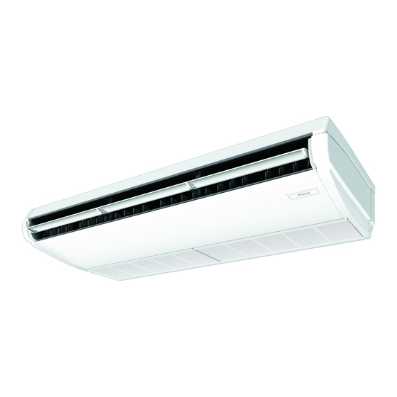
SPLIT SYSTEM
MODELS
(Ceiling Suspended type)
FHQ35CAVEB
FHQ50CAVEB
FHQ60CAVEB
FHQ71CAVEB
CAREFULLY READ THESE INSTRUCTIONS BEFORE INSTALLATION.
KEEP THIS MANUAL IN A HANDY PLACE FOR FUTURE REFERENCE.
LESEN SIE DIESE HINWEISE VOR DER INSTALLATION SORGFÄLTIG DURCH.
BEWAHREN SIE DIESE ANLEITUNG AN EINEM LEICHT ZUGÄNGLICHEN ORT FÜR
SPÄTERES NACHSCHLAGEN AUF.
VEUILLEZ LIRE ATTENTIVEMENT CES INSTRUCTIONS AVANT L'INSTALLATION.
CONSERVEZ CE MANUEL EN LIEU SÛR POUR POUVOIR VOUS Y REPORTER ULTÉRI-
EUREMENT.
LEA DETENIDAMENTE ESTAS INSTRUCCIONES ANTES DE LA INSTALACIÓN
CONSERVE ESTE MANUAL PARA POSIBLES CONSULTAS FUTURAS.
PRIMA DELL'INSTALLAZIONE, LEGGERE ATTENTAMENTE LE PRESENTI ISTRUZIONI.
CONSERVARE IL PRESENTE MANUALE IN UN LUOGO FACILMENTE ACCESSIBILE PER
RIFERIMENTO FUTURO.
ΔΙΑΒΑΣΤΕ ΠΡΟΣΕΚΤΙΚΑ ΑΥΤΕΣ ΤΙΣ ΟΔΗΓΙΕΣ ΠΡΙΝ ΤΗΝ ΕΓΚΑΤΑΣΤΑΣΗ
ΦΥΛΑΞΤΕ ΑΥΤΟ ΤΟ ΕΓΧΕΙΡΙΔΙΟ ΣΕ ΒΟΛΙΚΟ ΜΕΡΟΣ ΓΙΑ ΜΕΛΛΟΝΤΙΚΗ ΑΝΑΦΟΡΑ.
LEES DEZE INSTRUCTIES ZOGVULDIG DOOR VOORDAT MET DE INSTALLATIE WORDT
BEGONNEN.
BEWAAR DEZE HANDLEIDING VOOR TOEKOMSTIG GEBRUIK OP EEN GESCHIKTE
PLAATS ONDER HANDBEREIK.
LEIA ATENTAMENTE ESTAS INSTRUÇÕES ANTES DA INSTALAÇÃO.
MANTENHA ESTE MANUAL NUM LOCAL DE FÁCIL ACESSO PARA CONSULTA.
ПЕРЕД УСТАНОВКОЙ ВНИМАТЕЛЬНО ПРОЧИТАЙТЕ ДАННЫЕ ИНСТРУКЦИИ.
ХРАНИТЕ ДАННОЕ РУКОВОДСТВО В ЛЕГКО ДОСТУПНОМ МЕСТЕ ДЛЯ ЕГО
ПОСЛЕДУЮЩЕГО ИСПОЛЬЗОВАНИЯ.
MONTAJDAN ÖNCE BU YÖNERGELERİ DİKKATLİCE OKUYUN
DAHA SONRA BAKMAK ÜZERE BU KILAVUZU SAKLAYIN
INSTALLATION MANUAL
FHQ100CAVEB
FHQ125CAVEB
FHQ140CAVEB
FHQ140CAVEA
Air Conditioners
English
Deutsch
Français
Español
Italiano
Ελληνικά
Nederlands
Portugues
Русский
Advertisement
Table of Contents

Related Manuals for Daikin FHQ35CAVEB


Summary of Contents for Daikin FHQ35CAVEB
-
Page 1: Installation Manual
INSTALLATION MANUAL English SPLIT SYSTEM Air Conditioners Deutsch MODELS Français (Ceiling Suspended type) FHQ35CAVEB FHQ100CAVEB Español FHQ50CAVEB FHQ125CAVEB FHQ60CAVEB FHQ140CAVEB FHQ71CAVEB FHQ140CAVEA Italiano CAREFULLY READ THESE INSTRUCTIONS BEFORE INSTALLATION. Ελληνικά KEEP THIS MANUAL IN A HANDY PLACE FOR FUTURE REFERENCE. -
Page 2: Table Of Contents
FHQ35CAVEB FHQ100CAVEB FHQ50CAVEB FHQ125CAVEB SPLIT SYSTEM Air Conditioners Installation manual FHQ60CAVEB FHQ140CAVEB FHQ71CAVEB FHQ140CAVEA • Consult your dealer regarding what to do in case of refriger- ant leakage. CONTENTS When the air conditioner is installed in a small room, it is nec- essary to take proper measures so that the amount of any 1. -
Page 3: Before Installation
• Have the customer actually operate the air conditioner while CAUTION looking at the manual. • Install drain piping according to this installation manual to Instruct the customer how to operate the air conditioner (par- ensure good drainage, and insulate the piping to prevent ticularly cleaning of the air filters, operation procedures, and condensation. -
Page 4: Selection Of Installation Location
CARRY OUT THE WORK GIVING CAUTION TO THE Points of the operation explanation FOLLOWING ITEMS AND AFTER THE WORK IS In addition to the general usage, since the items in the COMPLETED CHECK THESE AGAIN. operation manual with the WARNING and CAU- TION marks are likely to result in human bodily injuries 1. -
Page 5: Preparation Before Installation
(2) Make holes for hanging bolts, piping outlet, drain pip- CAUTION ing outlet, and electric wiring inlet. • Install the indoor and outdoor units, power supply wiring, • Use the installation pattern paper (5). remote controller wiring and transmission wiring at least 1 •... -
Page 6: Installation Of The Indoor Unit
3) Remove the hanger. INSTALLATION OF THE INDOOR UNIT • Loosen 2 bolts for installing the hanger at both sides It is easy to attach the optional parts before installing the (M8) (4 places at left and right) within 10mm. indoor unit. -
Page 7: Refrigerant Piping Work
• Remove the stay for packing and delivering (reinforcing plate) before refrigerant piping work. (Refer to Fig. 18) ≤ 1° • The refrigerant is pre-charged in the outdoor unit. • When connecting the pipings to the air conditioner, make sure to use a spanner and a torque wrench as shown in Fig.13. - Page 8 CAUTION Gas side piping insulating method Insulation of field piping must be carried out up to the con- nection inside the casing. If the piping is exposed to the Do not leave atmosphere, it may cause sweating or burn due to touching Piping insulating material (unit side) clearance the piping, electric shocks or a fire due to the wiring touch-...
- Page 9 (1) For rear side piping • After piping is finished, cut the removed penetration cover • Remove the rear piping penetration cover, and connect along the shape of piping, and install. the piping. (Refer to Fig. 16 and Fig. 18) Also, for top panel penetration cover, as it was before removed, put the horizontal blade motor and thermistor (2) For upward piping...
-
Page 10: Drain Piping Work
DRAIN PIPING WORK (1) Carry out drain piping. Good • Carry out drain piping so that drainage can ensured. Supports 1-1.5m • Drain piping can be connected from the following direc- tions: For right rear/right side, refer to Fig. 18 of ‘‘6. REFRIGERANT PIPING WORK’’, and for left rear/left side, refer to Fig. -
Page 11: Electric Wiring Work
Metal clamp (2) Metal clamp (2) (accessory) (accessory) Sealing material (Large) (8) Applying direction Centralized drain piping Drain hose (1) Install with downward inclination If water stagnates in the (accessory) of 1/100 or more so that no air drain piping, the piping approx. -
Page 12: How To Connect Wirings And Wiring Example
• Make sure to earth the air conditioner. • If the above is not available, make sure to observe the follow- Earthing resistance should be according to applicable legis- ing items. lation. • 2 wirings of different sizes to the terminal block for power •... - Page 13 (4) Connect the remote controller wiring led from the routing WARNING hole to the terminals (P1 and P2) of the terminal block (X1M: 4P). (There is no polarity.) When wiring, form the wirings orderly so that the control After this is done, use the wiring fixture (11) and clamp (4) box lid can be securely fastened.
- Page 14 WIRING EXAMPLE NOTE NOTE NOTE NOTE 1. Terminal numbers of outdoor and indoor units must be CAUTION matched. Be sure to install an earth leakage breaker to the outdoor 2-1. Connect the remote controller only to the master unit. unit. 2-2.
-
Page 15: Mounting Suction Grille · Decoration Side Panel
(2) Connect crossover wiring between the terminals (P1, P2) 10. MOUNTING SUCTION GRILLE · DECO- inside the control box for the remote controller. (There is no RATION SIDE PANEL polarity.) (Refer to Fig. 34 and Table 3) Install securely in the reverse order when decoration side panel Terminal for remote and suction grille were removed. - Page 16 11-1 SETTING WHEN AN OPTIONAL ACCESSORY 11-5 SETTING FAN SPEED DURING THERMOSTAT IS ATTACHED • For setting when attaching an optional accessory, refer to the • Set the fan speed according to the using environment after installation manual attached to the optional accessory. consultation with your customer.
-
Page 17: Test Operation
(5) Turn on the main power supply switch again, and as in (1), • If interior work is still unfinished when test operation fin- change the SECOND CODE No. to “02”, individual setting. ishes, explain to the customer that the air conditioner (6) Perform field setting (Refer to 11-1 to 11-4) for the slave must not be operated until interior work is completed in unit. - Page 18 (1) Press the INSPECTION /TEST OPERATION but- Indoor heat exchanger Abnormal stop is applied ton, “ ” is displayed and “ 0 ” flashes. liquid pipe temperature depending on the model or sensor malfunction condition. (2) Press the PROGRAMMING TIME button and find the unit No.
-
Page 19: Wiring Diagram
Suction piping thermistor Wiring error between indoor Transmission error system malfunction (Out- and outdoor unit. Or Indoor (between indoor and out- door unit) and outdoor Printed Circuit door units) Board failure. Outdoor heat exchanger Abnormal stop is applied distributor liquid piping Transmission error Transmission between indoor depending on the model or... - Page 20 Fig. 40 English...
- Page 21 3P368557-1 EM12A008D (1502) HT...