Advertisement
Table of Contents
- 1 Specifications
- 2 Specifications
- 3 Panel Layout
- 4 Circuit Board Layout
- 5 Disassembly Procedure
- 6 Lsi Pin Description
- 7 IC Block Diagram
- 8 Circuit Boards
- 9 Test Program
- 10 Inspection
- 11 MIDI Implementation Chart
- 12 Parts List
- 13 Overall Assembly
- 14 Electrical Parts
- Download this manual
See also:
Owner's Manual
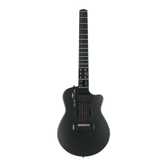
EZ-AG
SERVICE MANUAL
CONTENTS
SPECIFICATIONS ..................................................................... 3
PANEL LAYOUT ...................................................................... 4
CIRCUIT BOARD LAYOUT ...................................................... 5
BLOCK DIAGRAM ..........................................................................6
DISASSEMBLY PROCEDURE ................................................. 7
LSI PIN DESCRIPTION ............................................................. 9
IC BLOCK DIAGRAM ............................................................. 11
CIRCUIT BOARDS .................................................................. 12
TEST PROGRAM ................................................................... 16
INSPECTION .......................................................................... 18
MIDI IMPLEMENTATION CHART ......................................... 19
PARTS LIST
OVERALL CIRCUIT DIAGRAM
011700
PK
HAMAMATSU, JAPAN
1
Copyright (c) Yamaha Corporation. All rights reserved. PDF-K167
'03.11
Advertisement
Table of Contents

Related Manuals for Yamaha EZ-AG


Summary of Contents for Yamaha EZ-AG
- Page 1 LSI PIN DESCRIPTION ............. 9 IC BLOCK DIAGRAM ............. 11 CIRCUIT BOARDS ..............12 TEST PROGRAM ..............16 INSPECTION ................18 MIDI IMPLEMENTATION CHART ......... 19 PARTS LIST OVERALL CIRCUIT DIAGRAM 011700 HAMAMATSU, JAPAN Copyright (c) Yamaha Corporation. All rights reserved. PDF-K167 ’03.11...
-
Page 2: Specifications
IMPOR TANT NOTICE This manual has been provided for the use of authorized Yamaha Retailers and their service personnel. It has been assumed that basic service procedures inherent to the industry, and more specifically Yamaha Products, are already known and under- stood by the users, and have therefore not been restated. -
Page 3: Specifications
EZ-AG SPECIFICATIONS Strings Frets Displays LED display, 6 x 6 fret LEDs Sounds 9 guitar, 8 bass, 3 others STRUM (right hand), CHORD (left hand), BOTH (both hands) Play Modes Controls [STANDBY/ON] switch, [STRUM] button, [CHORD] button, [BOTH] button, [DEMO] button, [SOUND] button, [SONG] button, [TEMPO] button,... -
Page 4: Panel Layout
EZ-AG PANEL LAYOUT Body Frets Control Section Strings Bridge Plate Connector & Power Switch Section Control Section VALUE [+]/[-] buttons Display [VOLUME] button [TUNING] button [TEMPO] button [CAPO] button [SONG] button [SOUND] button [DEMO] button PLAY MODE [1]/[STRUM], [2]/[CHORD], [3]/[BOTH] buttons Connector &... -
Page 5: Circuit Board Layout
EZ-AG CIRCUIT BOARD LAYOUT <Bottom view> Battery cover assembly <Top view> Bottom assembly CN801 CN802 <Bottom view> <Bottom view> Neck assembly CN501 CN601 CN604 CN701 • First lot Strings sensor unit Top assembly MUTE Adhesive connector tape assembly... - Page 6 SENSOR PIEZO UNIT SENSOR CN903 (4P) Earth 9,10 LD90 STRING Plate SW MATRIX S1-S6 MUTE CN902 (4P) 8X10 S [0-11] S [0-11] PIEZO Driver D [0-7] D [0-7] PLATE SPEAKER SENSOR IC1 (64P) L [0-15] L [0-14] 4 Ω TA1,3 7 Seg LED LED MATRIX (18P)
-
Page 7: Disassembly Procedure
EZ-AG DISASSEMBLY PROCEDURE Caution: Be sure to attach the removed filament tape just as it was before removal. Bottom Assembly AM Circuit Board (Time required: About 2 minutes) (Time required: About 4 minutes) Remove the eight (8) screws marked [110A],the two Remove the bottom assembly. - Page 8 EZ-AG Strings Sensor Unit PN Circuit Board, Key Top Rubber (Time required: About 3 minutes) (Time required: About 4 minutes) Remove the bottom assembly. (See procedure 1.) Remove the bottom assembly. (See procedure 1.) Remove the four (4) screws marked [130B] and the Remove the three (3) screws marked [N100].
-
Page 9: Lsi Pin Description
EZ-AG LSI PIN DESCRIPTION MN101C027YB (XS711200) CPU PN: IC001 NAME FUNCTION NAME FUNCTION Switch matrix data Switch matrix data MIDI transmit data VREF+ Power supply (+5V, analog) Switch matrix data Power supply (+5V) OSC2 Crystal oscillator (8MHz) OSC1 Crystal oscillator (8MHz) - Page 10 EZ-AG HG73C205AFD (XU947C00) SWX00B (Tone Generator) DM: IC101 NAME FUNCTION NAME FUNCTION Initial clear CMA3 Program address bus RFCLKI PLL Clock CMA8 Program address bus PLL Control CMA2 Program address bus Power supply read signal AVDD_PLL AVSS_PLL Ground CMA1 Program address bus...
-
Page 11: Ic Block Diagram
EZ-AG IC BLOCK DIAGRAM 74HCU04DT (XZ110A00) HD74LVC08FP (XU720A00) SN74LV4053APWR (X2719A00) DM: IC607 DM: IC306 DM: IC701 TC74HCT04AF-T1 (XI297A00) Quad 2 Input AND Triple 2-Channel MM74HCU04SJX (X0294A00) Multiplexer/Demultiplexer DM: IC702 Hex Inverter Switches IN/OUT Switches IN/OUT Commons OUT/IN Switches IN/OUT Commons OUT/IN... -
Page 12: Circuit Boards
EZ-AG CIRCUIT BOARDS CONTENTS AM Circuit Board (X3960B0) ............12 DM Circuit Board (X4489B0) ............13 PN Circuit Board (X3961B0) ............. 14/15 SE Circuit Board (X3960B0) ............12 SE1 Circuit Board (X3960B0) ............12 Note: See parts list for details of circuit board component parts. - Page 13 EZ-AG DM Circuit Board to SE-CN901, to MUTE-PLATE Speaker to AM-CN801 to PN-CN3 not installed Component side Pattern side 2NA-WA83340...
- Page 14 EZ-AG PN Circuit Board to DM-CN701 STRING-1 STRING-2 STRING-3 STRING-4 STRING-5 STRING-6 Component side 2NA-WA83470...
- Page 15 EZ-AG PN Circuit Board FRET-1 FRET-2 FRET-3 FRET-4 FRET-5 FRET-6 FRET-7 FRET-8 FRET-9 FRET-10 FRET-11 FRET-12 PLAY MODE VALUE- VALUE+ STRUM CHORD BOTH RESET START/STOP START/STOP START/STOP TEMPO VOLUME DEMO SOUND SONG START/STOP SELECT SELECT CAPO TUNING Pattern side 2NA-WA83470...
-
Page 16: Test Program
EZ-AG TEST PROGRAM Preparation PA-3C, PA-32 (AC adaptor) is used. Jigs: Frequency counter, level meter (with JIS-C filter), MIDI cable Note) Connect a stereo plug to the [PHONES/OUTPUT] jack at 33 ohms. [STANDBY/ON] How to enter the Test Mode While pressing the 1st fret, 2nd fret and 3rd fret of 6th string, turn the [STANDBY/ON] switch on. - Page 17 EZ-AG TEST 7-seg. LED for Each Test Test Function and Judgment criteria Check the switches and the LEDs on the panel. Press the switches as shown on the LEDs in the sequence indicated in TABLE 1 (P.18). A sound is generated while the fret switch is pressed. (No key stick is existed.) Press the [DEMO] button to interrupt operation.
-
Page 18: Inspection
EZ-AG <TABLE1> DEMO SOUND SONG STRUM CHORD BOTH TEMPO VOLUME CAPO 1st fret of 2nd fret of 12th fret of 1st fret of 12th fret of TUNING – 1st string 1st string 1st string 2nd string 6th string 6 11 12... -
Page 19: Midi Implementation Chart
EZ-AG MIDI IMPLEMENTATION CHART YAMAHA [ EZ GUITAR ] Date: 11-June-2003 Model EZ-AG MIDI Implementation Chart Version : 1.0 Function... Transmitted Recognized Remarks Basic Default 1 - 6 1 - 16 Channel Changed 1 - 16 Default Mode Messages Altered... - Page 20 EZ-AG NOTE: EZ-AG functions as a 16-channel multi-timbral tone generator, and incoming data does not affect the panel voices or panel settings. However, the MIDI messages listed below do affect the panel voices and songs. • MIDI Master Tuning Control change <RPN>...
-
Page 21: Parts List
PARTS LIST CONTENTS OVERALL ASSEMBLY ............. 2 STRINGS SENSOR UNIT ............4 ELECTRICAL PARTS ............6-11 Notes : DESTINATION ABBREVIATIONS A : Australian model M : South African model B : British model O : Chinese model C : Canadian model Q : South-east Asia model D : German model T : Taiwan model... -
Page 22: Overall Assembly
EZ-AG OVERALL ASSEMBLY Neck Assembly 180a N110 N100 Top Assembly Bottom Assembly B120 B190 B110 B200 B110 B120 B100 B150 B160 B180 B170 B180 Strings Sence Unit Battery Cover Assembly... - Page 23 EZ-AG PART NO. DESCRIPTION REMARKS REF NO. RANK OVERALL ASSEMBLY EZ-AG (WA61820) Top Assembly (WB41840) Bottom Assembly (WB41850) WA968200 Strings Sensor Unit Neck Assembly (WB41820) WB768000 Battery Cover Assembly Battery Cover Black (WB63990) Nonwoven Fabric Cloth 84X15X0.7 (WB76790) WA441500 Cord Binder...
- Page 24 EZ-AG STRINGS SENSOR UNIT It can not be disassembled.
- Page 25 EZ-AG PART NO. DESCRIPTION REMARKS REF NO. RANK WA968200 STRINGS SENSOR UNIT EZ-AG Sensor Base (WA89330) Sensor 7BB-12-9A6 Piezo (V905470) Adhesive Tape 15X15X0.16 (WB45000) Bracket (V852360) Bracket (V852740) String 1.0 GS (WA96890) String 1.2 GS (WA96900) WA849500 Circuit Board SE (SE+SE1)
-
Page 26: Electrical Parts
EZ-AG ELECTRICAL PARTS PART NO. DESCRIPTION REMARKS REF NO. RANK ELECTRICAL PARTS EZ-AG WA849400 Circuit Board (WA83390)(X3960B0) WA849500 Circuit Board SE (SE+SE1) (WA83390)(X3960B0) WA849300 Circuit Board (WA83340)(X4489B0) WA849700 Circuit Board (WA83470)(X3961B0) WA849400 Circuit Board (WA83390)(X3960B0) Circuit Board SE (SE+SE1) (WA83390)(X3960B0) - Page 27 EZ-AG PART NO. DESCRIPTION REMARKS REF NO. RANK C0102 US061270 Ceramic Capacitor-CH(chip) 27P 50V J C0103 US064100 Ceramic Capacitor-B (chip) 0.0100 50V K C0104 US064100 Ceramic Capacitor-B (chip) 0.0100 50V K C0105 US145100 Ceramic Capacitor-F (chip) 0.1000 25V Z C0106 VV020700 Monolithic Ceramic Cap.
- Page 28 EZ-AG PART NO. DESCRIPTION REMARKS REF NO. RANK CN601 VB858800 Connector Base Post PH 9P SE CN604 VB858100 Connector Base Post PH 2P SE CN701 VB858400 Connector Base Post PH 5P SE D0501 VZ060500 Diode SFPB-62V D0502 VV925900 Diode RLS-73 TE-11...
- Page 29 EZ-AG PART NO. DESCRIPTION REMARKS REF NO. RANK R0049 RD358390 Carbon Resistor (chip) 390.0K 63M J R0050 RD356560 Carbon Resistor (chip) 5.6K 63M J R0051 RD358100 Carbon Resistor (chip) 100.0K 63M J R0052 RD350000 Carbon Resistor (chip) 0 63M J...
- Page 30 EZ-AG PART NO. DESCRIPTION REMARKS REF NO. RANK ZD601 WB426000 Zener Diode RD2.0S-T1 2.0V -606 WB426000 Zener Diode RD2.0S-T1 2.0V WA849700 Circuit Board (WA83470)(X3961B0) C0001 VV020700 Monolithic Ceramic Cap. 10.000 10V K C0005 VV020700 Monolithic Ceramic Cap. 10.000 10V K...
- Page 31 EZ-AG PART NO. DESCRIPTION REMARKS REF NO. RANK Sensor 7BB-12-9A6 Piezo (V905470) : New Parts RANK: Japan only...
- Page 32 EZ-AG OVERALL CIRCUIT DIAGRAM 1/2 ( DM ) EZ-AG TMUTE [0-5] OP AMP DC-DC CONVERTER INVERTER DC-DC CONVERTER to MUTE Plate OP AMP MUTE AMP OP AMP INVERTER ** ** INVERTER OP AMP VCC/LINE OUT/MIDI ** ** INVERTER STRINGS, PIEZO SENSOR...
- Page 33 EZ-AG OVERALL CIRCUIT DIAGRAM 2/2 ( AM, SE, SE1, PN ) EZ-AG STANDBY BATTERY (LR6 “AA” SIZE x 6) AC ADAPTOR POWER AMP PA-3C to DM-CN501 DC IN 12V STRING PIEZO SENSOR 28CC1-8826576 28CC1-8826576 S1~S6 to DM-CN601 PHONES/OUTPUT PHOTO COUPLER...