Sony CDP-CX90ES Service Manual
Hide thumbs
Also See for CDP-CX90ES:
- Operating instructions manual (32 pages) ,
- Operating instructions manual (125 pages) ,
- Limited warranty (1 page)
Table of Contents
Advertisement
Quick Links
QQ
3 7 63 1515 0
CDP-CX90ES/CX270
SERVICE MANUAL
TE
L 13942296513
www
.
MICROFILM
http://www.xiaoyu163.com
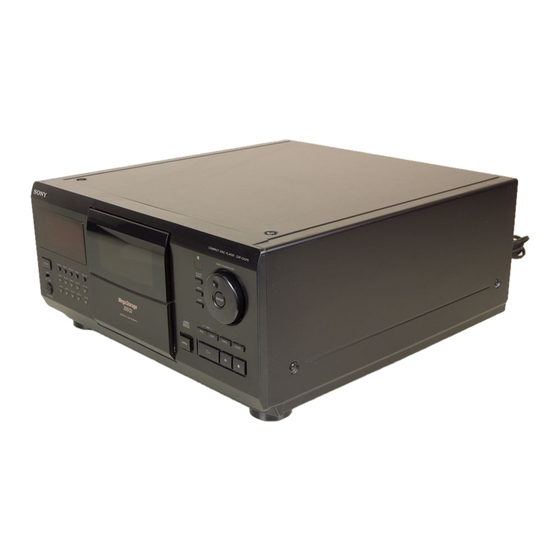
PHOTO : CDP-CX90ES
x
ao
u163
y
i
http://www.xiaoyu163.com
2 9
8
Model Name Using Similar Mechanism
CD Mechanism Type
Base Unit Type
Q Q
Optical Pick-up Type
3
6 7
1 3
1 5
SPECIFICATIONS
co
.
— 1 —
9 4
2 8
US Model
Canadian Model
CDP-CX90ES/CX270
AEP Model
CDP-CX250
CDM-40
KSM-213BKN/M-N
KSS-213B/S-N
0 5
8
2 9
9 4
2 8
(USA, Canadian model)
220V-230V AC, 50Hz (AEP, German model)
COMPACT DISC PLAYER
m
9 9
CDP-CX270
9 9
Advertisement
Table of Contents

Related Manuals for Sony CDP-CX90ES


Summary of Contents for Sony CDP-CX90ES
- Page 1 3 7 63 1515 0 CDP-CX90ES/CX270 SERVICE MANUAL US Model Canadian Model CDP-CX90ES/CX270 AEP Model CDP-CX270 PHOTO : CDP-CX90ES Model Name Using Similar Mechanism CDP-CX250 CD Mechanism Type CDM-40 Base Unit Type KSM-213BKN/M-N Optical Pick-up Type KSS-213B/S-N L 13942296513...
-
Page 2: Table Of Contents
http://www.xiaoyu163.com 3 7 63 1515 0 MODEL IDENTIFICATION TABLE OF CONTENTS — BACK PANEL — 1. SERVICING NOTE ............3 2. GENERAL ..............3. DISASSEMBLY 3-1. Front Panel Assembly ............15 4-983-366- 3-2. Back Panel Assembly ............15 3-3. Table Assembly ..............16 3-4. -
Page 3: Servicing Note
FONCTIONNEMENT. NE REMPLACER CES COMPOSANTS u163 WHOSE PART NUMBERS APPEAR AS SHOWN IN THIS QUE PAR DES PIÈCES SONY DONT LES NUMÉROS MANUAL OR IN SUPPLEMENTS PUBLISHED BY SONY. SONT DONNÉS DANS CE MANUEL OU DANS LES SUPPLÉMENTS PUBLIÉS PAR SONY. -
Page 4: General
http://www.xiaoyu163.com 3 7 63 1515 0 SECTION 2 GENERAL LOCATION OF PARTS AND CONTROLS Front Panel !£ !¢ !∞ !§ 90!¡ !™ @∞ @¢ @£ @™ @¡ @º !ª !¶ @§ !• L 13942296513 1 POWER button !¢ ENTER button 2 CONTINUE button !∞... - Page 5 http://www.xiaoyu163.com 3 7 63 1515 0 This section is extracted from instruction manual. L 13942296513 u163 — 5 — http://www.xiaoyu163.com...
- Page 6 http://www.xiaoyu163.com 3 7 63 1515 0 L 13942296513 u163 — 6 — http://www.xiaoyu163.com...
- Page 7 http://www.xiaoyu163.com 3 7 63 1515 0 L 13942296513 u163 — 7 — http://www.xiaoyu163.com...
- Page 8 http://www.xiaoyu163.com 3 7 63 1515 0 L 13942296513 u163 — 8 — http://www.xiaoyu163.com...
- Page 9 http://www.xiaoyu163.com 3 7 63 1515 0 L 13942296513 u163 — 9 — http://www.xiaoyu163.com...
- Page 10 http://www.xiaoyu163.com 3 7 63 1515 0 L 13942296513 u163 — 10 — http://www.xiaoyu163.com...
- Page 11 http://www.xiaoyu163.com 3 7 63 1515 0 L 13942296513 u163 — 11 — http://www.xiaoyu163.com...
- Page 12 http://www.xiaoyu163.com 3 7 63 1515 0 L 13942296513 u163 — 12 — http://www.xiaoyu163.com...
- Page 13 http://www.xiaoyu163.com 3 7 63 1515 0 L 13942296513 u163 — 13 — http://www.xiaoyu163.com...
- Page 14 http://www.xiaoyu163.com 3 7 63 1515 0 L 13942296513 u163 — 14 — http://www.xiaoyu163.com...
-
Page 15: Disassembly
http://www.xiaoyu163.com 3 7 63 1515 0 SECTION 3 DISASSEMBLY 3-1. FRONT PANEL ASSEMBLY 1 Two screws 8 Remove the claw (BVTP 3x8) 2 Two screws (BVTP 3x8) 7 Remove the claw 4 Two screws (BVTT 3x6) 9 Front panel assembly 6 Connector (Main board, CN404) 5 Flat type wire (23 core) (Main board, CN403) -
Page 16: Table Assembly
http://www.xiaoyu163.com 3 7 63 1515 0 3-3. TABLE ASSEMBLY 2 Three screws (BVTT 3x6) Main board 4 Connector (CN308) 5 Guide assembly 3 Screw (PSW 3x6) 1 Screw (BVTT 3x6) 9 Three screws (BVTT 3x6) L 13942296513 6 Stop ring (E type) 0 Three holder assemblies !¡... -
Page 17: Mechanism Deck
http://www.xiaoyu163.com 3 7 63 1515 0 3-4. MECHANISM DECK 1 Flat type wire 5 Mechanism deck (23core) (CN301) Main board Jack board Main board 2 Connector (CN304) 3 Connector (CN504) L 13942296513 4 Nine screws (BVTT 3x8) 3-5. BASE UNIT 1 Screw (BVTT 3x6) 2 Fulcrum plate (BU UPPER) assy... -
Page 18: Test Mode
http://www.xiaoyu163.com 3 7 63 1515 0 SECTION 4 TEST MODE 4-1. Display Check Mode 4-3. Key and Display Check Mode With the power turned off (standby state), press the POWER button To set this mode, connect the test point (AFADJ) on the MAIN board while pressing the P (pause) button. - Page 19 http://www.xiaoyu163.com 3 7 63 1515 0 4-4. Aging Mode Special Aging Mode Functions The aging mode is provided with the following convenient functions • Disc setting mode (*1) Aging Mode • Selection of presence of protection function during error (*2) •...
- Page 20 http://www.xiaoyu163.com 3 7 63 1515 0 Aging Method 6. Press the ( button. 7. The ( LED blinks, the aging mode is set, and aging is started. 1. Turn ON the power of the unit. Open the front cover. 2. Press the AGING START button of the remote commander for 8.
-
Page 21: Adjustments
http://www.xiaoyu163.com 3 7 63 1515 0 SECTION 5 ADJUSTMENTS 5-1. MECHANICAL ADJUSTMENT Perform the following steps before carrying out adjustments. 1. Turn ON the power of the unit, set disc to disc table No. 92, and perform chucking. 2. Turn OFF the power. 3. - Page 22 http://www.xiaoyu163.com 3 7 63 1515 0 GUIDE (DISC T) ALIGNMENT Holder (guide T) Guide (disc T) Fixed screw (1)Rotate the cam and adjust to the position shown in the figure. Guide (disc T) L 13942296513 (2)Check that the state is as shown in the figure.
- Page 23 http://www.xiaoyu163.com 3 7 63 1515 0 HOLDER (DISC A) ALIGNMENT Holder (disc A) Thrust screw (1)Rotate the cam and adjust to the position shown in the figure. Disc 0 – 1 mm Holder (disc A) L 13942296513 (2)Check that the state is as shown in the figure.
- Page 24 http://www.xiaoyu163.com 3 7 63 1515 0 SENSOR ALIGNMENT Perform this adjustment after the “holder (disc A) adjustment”. If the disc table swings to the left and right just before the disc is chucked, perform the following adjustment. LEVER (stopper) assembly (1)Rotate the cam and adjust to the position Bracket (sensor) shown in the figure.
- Page 25 http://www.xiaoyu163.com 3 7 63 1515 0 PULLY AND DISC CENTER HOLE ALIGNMENT Base unit Bracket (BU adjustment) (1)Rotate the cam and adjust to the position shown in the figure. Magnet assembly (2)Check that the state is as shown in the figure. 0.5 –...
- Page 26 http://www.xiaoyu163.com 3 7 63 1515 0 MAGNET ASSY ALIGNMENT Adjustment screw Magnet assy (1)Rotate the cam and adjust to the posi- tion shown in the figure. Disc Magnet holder L 13942296513 Magnet assy Adjustment screw 1 2 3 4 1 2 3 4 (3)Apply suitable locking compaund to the part after adjusting.
-
Page 27: Electrical Block Checking
http://www.xiaoyu163.com 3 7 63 1515 0 5-2. ELECTRICAL BLOCK CHECKING Note: Note: A clear RF signal waveform means that the shape “◊” can be clearly distinguished at the center of the waveform. 1. CD Block is basically designed to operate without adjustment. Therefore, check each item in order given. - Page 28 http://www.xiaoyu163.com 3 7 63 1515 0 Monitor screen RF PLL Free-run Frequency Check Procedure : 1. Connect frequency counter to test point TP (PLCK) with lead wire. frequency counter BD (TEXT) board TP (PLCK) 2. Turn Power switch on. 3. Put the disc (YEDS-18) in to play the number five track. Adjust C510 so that width of the Orange frame (A) at the right of the Confirm that reading on frequency counter is 4.3218MHz.
- Page 29 http://www.xiaoyu163.com 3 7 63 1515 0 9. Disconnect the resistor connected to Pin 4 of CN305 of the MAIN Waveform 2 board. (Connection 2) 10. Observe the waveform on the oscilloscope. (Waveform 2) 11. Adjust RV401 of the MAIN board so that the waveform on the oscilloscope satisfies the following adjustment value 1.
- Page 30 http://www.xiaoyu163.com 3 7 63 1515 0 Adjustment Location : [ BD (TEXT) BOARD ] — Side B — IC101 (PLCK) TP (VC) TP (FE1) TP (RF) IC103 (TE) [ MAIN BOARD ] — Component Side — DISC SENSOR L 13942296513 ADJUSTMENT for T.
-
Page 31: Diagrams
http://www.xiaoyu163.com 3 7 63 1515 0 SECTION 6 DIAGRAMS 6-1. CIRCUIT BOARDS LOCATION LUMINOUS board MAIN board T SENS. board ILLUMINATION board SW board (AEP, G) OUTLET board (AEP, G) KEY BOARD board DISP board JACK board L 13942296513 DOOR SW board T. -
Page 32: Ic101 Digital Servo, Digital Signal Processor (Cxd2545Q)
http://www.xiaoyu163.com 3 7 63 1515 0 6-2. IC PIN FUNCTIONS • IC101 DIGITAL SERVO, DIGITAL SIGNAL PROCESSOR (CXD2545Q) Pin No. Pin Name Function SRON Sled drive output (Open) SRDR Sled drive output SFON Sled drive output (Open) TFDR Tracking drive output TRON Tracking drive output (Open) TRDR... - Page 33 http://www.xiaoyu163.com 3 7 63 1515 0 Pin No. Pin Name Function – Digital power supply ASYE Asymmetry circuit ON/OFF (Connected to +5V) PSSL Audio data output mode selection input (Connected to Ground) WDCK 48-bit slot D/A interface. Word clock. (Open) LRCK 48-bit slot D/A interface.
- Page 34 http://www.xiaoyu163.com 3 7 63 1515 0 Pin No. Pin Name Function XRST System reset DIRC Used in 1-track jump mode (Connected to +5v) SCLK SENS serial data read-out clock DFSW Defect selection pin (Connected to Ground) ATSK Input pin for anti-shock (Connected to Ground) DATA Serial data input, supplied from CPU XLAT...
-
Page 35: Ic401 System Control (Mb90677)
http://www.xiaoyu163.com 3 7 63 1515 0 • IC401 SYSTEM CONTROL (MB90677) Pin No. Pin Name Function Address terminal for external RAM/ROM Chip select Chip select Chip select ADJ mode input pin AF ADJ AFADJ mode input pin –– Open –– Open Address latch enable Lower during read... - Page 36 http://www.xiaoyu163.com 3 7 63 1515 0 Pin No. Pin Name Function KEY3 Key input – Ground pin CD1/2/3 Command mode switch FL. SLCT Fluorescent indicator tube select port for different destination T. DRV Table driver D. SENS Disc sensor input L.
- Page 37 http://www.xiaoyu163.com 3 7 63 1515 0 Pin No. Pin Name Function XGND – Ground X'tal oscillator terminal X'tal oscillator terminal XVDD – +5V terminal D00/A00 Data/Address common terminal for external RAM/ROM D01/A01 Data/Address common terminal for external RAM/ROM D02/A02 Data/Address common terminal for external RAM/ROM D03/A03 Data/Address common terminal for external RAM/ROM D04/A04...
-
Page 38: Ic407 Osd (Mb90095-Oem166)
http://www.xiaoyu163.com 3 7 63 1515 0 • IC407 OSD (MB90095-OEM166) Pin No. Pin Name Function –– Luminance signal input terminal for superimpose displays – –– Chroma signal input terminal for superimpose displays – –– Composite signal input terminal for superimpose displays –... - Page 39 http://www.xiaoyu163.com w w w http://www.xiaoyu163.com...
- Page 40 http://www.xiaoyu163.com w w w http://www.xiaoyu163.com...
- Page 41 http://www.xiaoyu163.com w w w http://www.xiaoyu163.com...
- Page 42 http://www.xiaoyu163.com w w w http://www.xiaoyu163.com...
- Page 43 http://www.xiaoyu163.com http://www.xiaoyu163.com...
- Page 44 http://www.xiaoyu163.com http://www.xiaoyu163.com...
-
Page 45: Exploded Views
http://www.xiaoyu163.com 3 7 63 1515 0 SECTION 7 EXPLODED VIEWS NOTE: The components identified by • Abbreviation • Items marked “*” are not stocked since they are mark ! or dotted line with mark CND : Canadian model seldom required for routine service. Some delay ! are critical for safety. -
Page 46: Disc Table Section
http://www.xiaoyu163.com 3 7 63 1515 0 7-2. DISC TABLE SECTION not supplied supplied not supplied not supplied not supplied supplied supplied L 13942296513 not supplied supplied M801 supplied supplied Ref. No. Part No. Description Remark Ref. No. Part No. Description Remark * 51 1-661-466-11 T.MOTOR BOARD... -
Page 47: Front Panel Section
* 129 A-4699-088-A JOG BOARD, COMPLETE (EXCEPT AEP,G) 4-977-358-11 CUSHION (8X12.5) * 129 A-4699-530-A JOG BOARD, COMPLETE (AEP,G) u163 4-963-404-21 EMBLEM (5-A), SONY * 130 4-982-812-01 HOLDER (LED) X-4947-219-1 PLATE (A) ASSY, FULCRUM 4-951-620-01 SCREW (2.6X8), +BVTP 4-982-797-11 SPRING (A), TORSION... -
Page 48: Mechanism Section-1 (Cdm-40)
http://www.xiaoyu163.com 3 7 63 1515 0 7-4. MECHANISM SECTION-1 (CDM-40) not supplied not supplied not supplied L 13942296513 not supplied Ref. No. Part No. Description Remark Ref. No. Part No. Description Remark X-4947-241-1 LEVER (C) ASSY A-4672-092-A MAGNET ASSY 4-982-882-01 SPRING (LIMITTER), TORSION 3-366-559-02 MAGNET (CHUCK) 4-982-881-01 SPRING (HOLDER), TORSION 4-960-633-01 YOKE (MAGNET) -
Page 49: Mechanism Section-2 (Cdm-40)
http://www.xiaoyu163.com 3 7 63 1515 0 7-5. MECHANISM SECTION-2 (CDM-40) not supplied not supplied L 13942296513 not supplied M802 Ref. No. Part No. Description Remark Ref. No. Part No. Description Remark 4-976-465-01 GEAR (LOADING 1) X-4947-227-1 LEVER (STOPPER) ASSY 4-976-466-01 GEAR (LOADING 2) 4-982-893-01 GEAR (CENTER 2) 4-951-291-01 SCREW X-4947-607-1 GEAR (PULLEY) ASSY... -
Page 50: Base Unit Section-1 (Ksm-213Bkn/M-N)
http://www.xiaoyu163.com 3 7 63 1515 0 7-6. BASE UNIT SECTION-1 (KSM-213 BKN/M-N) L 13942296513 Ref. No. Part No. Description Remark Ref. No. Part No. Description Remark 3-356-601-11 SCREW, STEP 4-982-872-01 SPRING (F-2), TENSION X-4947-244-1 SLIDER (BU ADJUSTMENT) ASSY 4-982-871-01 SPRING (F-1), TENSION X-4947-243-1 HOLDER (BU) ASSY 4-982-858-01 DAMPER 4-982-859-01 HOLDER (DAMPER) -
Page 51: Base Unit Section-2 (Ksm-213Bkn/M-N)
http://www.xiaoyu163.com 3 7 63 1515 0 7-7. BASE UNIT SECTION-2 (KSM-213 BKN/M-N) not supplied not supplied not supplied L 13942296513 M101 not supplied M102 The components identified by mark ! or dotted line with mark ! are critical for safety. Replace only with part number specified. -
Page 52: Electrical Parts List
http://www.xiaoyu163.com 3 7 63 1515 0 SECTION 8 BD (TEXT) ELECTRICAL PARTS LIST Note: • Due to standardization, replacements in the parts list • SEMICONDUCTORS The components identified by may be different from the parts specified in the dia- In each case, u: µ , for example: mark ! or dotted line with mark grams or the components used on the set. - Page 53 http://www.xiaoyu163.com 3 7 63 1515 0 BD (TEXT) DISP DOOR SW Ref. No. Part No. Description Remark Ref. No. Part No. Description Remark R161 1-216-308-00 METAL CHIP 1/10W R815 1-247-843-11 CARBON 3.3K 1/4W R162 1-216-101-00 METAL CHIP 150K 1/10W R816 1-249-427-11 CARBON 6.8K 1/4W F...
- Page 54 http://www.xiaoyu163.com 3 7 63 1515 0 JACK ILLUMINATION Ref. No. Part No. Description Remark Ref. No. Part No. Description Remark 1-661-471-11 ILLUMINATION BOARD C911 1-164-159-11 CERAMIC 0.1uF ****************** C912 1-124-997-11 ELECT 470uF C913 1-126-163-11 ELECT 4.7uF < CONNECTOR > C914 1-126-163-11 ELECT 4.7uF CN810...
- Page 55 http://www.xiaoyu163.com 3 7 63 1515 0 JACK KEYBOARD Ref. No. Part No. Description Remark Ref. No. Part No. Description Remark < TRANSISTOR > < IC > Q470 8-729-620-05 TRANSISTOR 2SC2603-EF IC804 8-759-373-49 IC NJL54H400 Q901 8-729-119-76 TRANSISTOR 2SA1175-HFE Q902 8-729-119-76 TRANSISTOR 2SA1175-HFE <...
- Page 56 http://www.xiaoyu163.com 3 7 63 1515 0 KEYBOARD MAIN L.MOTOR L.SW LUMINOUS Ref. No. Part No. Description Remark Ref. No. Part No. Description Remark < DIODE > < CAPACITOR > D821 8-719-109-85 DIODE RD5.1ES-B2 C002 1-126-101-11 ELECT 100uF D822 8-719-109-85 DIODE RD5.1ES-B2 C301 1-163-038-91 CERAMIC CHIP 0.1uF...
- Page 57 http://www.xiaoyu163.com 3 7 63 1515 0 MAIN Ref. No. Part No. Description Remark Ref. No. Part No. Description Remark C456 1-163-037-11 CERAMIC CHIP 0.022uF C631 1-130-483-00 MYLAR 0.01uF (CX90ES) C480 1-163-038-91 CERAMIC CHIP 0.1uF C481 1-163-038-91 CERAMIC CHIP 0.1uF C632 1-130-483-00 MYLAR 0.01uF (CX90ES)
- Page 58 http://www.xiaoyu163.com 3 7 63 1515 0 MAIN Ref. No. Part No. Description Remark Ref. No. Part No. Description Remark IC701 8-759-712-02 IC NJM2114D C734 1-136-850-11 FILM 0.1uF IC702 8-759-602-83 IC M5238P (CX90ES) IC703 8-759-900-72 IC NE5532P < CONNECTOR > < COIL > * CN301 1-568-839-11 SOCKET, CONNECTOR 23P CN304...
- Page 59 http://www.xiaoyu163.com 3 7 63 1515 0 MAIN Ref. No. Part No. Description Remark Ref. No. Part No. Description Remark R439 1-220-227-11 METAL GLAZE 1/4W 1-216-295-91 CONDUCTOR, CHIP(2012) R440 1-220-227-11 METAL GLAZE 1/4W (CX90ES/CX270:US,CND) R301 1-216-049-91 METAL GLAZE 1/10W R441 1-216-001-00 METAL CHIP 1/10W R442 1-216-001-00 METAL CHIP...
- Page 60 http://www.xiaoyu163.com 3 7 63 1515 0 MAIN RAY-CATCHER OUTLET BOARD Ref. No. Part No. Description Remark Ref. No. Part No. Description Remark R621 1-216-687-11 METAL CHIP 0.5% 1/10W R721 1-216-687-11 METAL CHIP 0.5% 1/10W (CX270) (CX270) R622 1-216-635-11 METAL CHIP 0.5% 1/10W R722...
- Page 61 http://www.xiaoyu163.com 3 7 63 1515 0 RAY-CATCHER T.MOTOR T.SENS Ref. No. Part No. Description Remark Ref. No. Part No. Description Remark < TRANSISTOR > FL801 1-517-565-11 INDICATOR TUBE, FLUORESCENT M101 X-2626-234-1 T.T CHAISSIS ASSY (MG)(K)(SPINDLE) Q801 8-729-926-31 PHOTO TRANSISTOR PT483F1S M102 X-2625-769-1 MOTOR GEAR ASSY (MB)(RP(SLED) M801...
- Page 62 7-621-775-20 SCREW +B 2.6X5 7-621-255-15 SCREW +P 2X3 7-682-547-04 +B 3X6 L 13942296513 u163 English 96H090467-1 Printed in Japan Sony Corporation © 1996.8 9-960-731-11 Home A&V Products Company Published by Service and Safety Engineering Dept. (Shibaura) — 82 — http://www.xiaoyu163.com...