Pioneer MEP-7000 Service Manual
Multi entertainment player
Hide thumbs
Also See for MEP-7000:
- Operating instructions manual (208 pages) ,
- Control manual (16 pages) ,
- Guía de control (16 pages)
Table of Contents
Advertisement
Quick Links
Download this manual
See also:
Control Manual
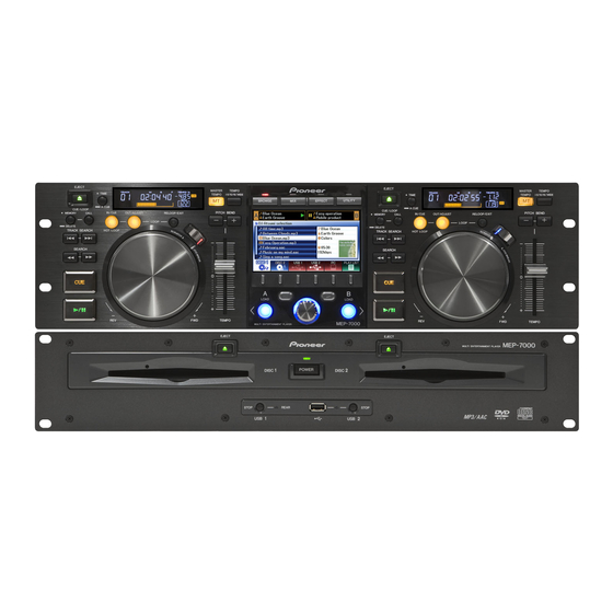
MULTI ENTERTAINMENT PLAYER
MEP-7000
THIS MANUAL IS APPLICABLE TO THE FOLLOWING MODEL(S) AND TYPE(S).
Model
MEP-7000
KUCXJ
MEP-7000
WYXJ5
MEP-7000
TLFXJ
MEP-7000
WAXJ5
: This product comprises a control unit (CU-V170) and a drive unit. Note that
a user should bring in both units for servicing.
For details, refer to "Important Check Points for good servicing".
PIONEER CORPORATION
PIONEER ELECTRONICS (USA) INC. P.O. Box 1760, Long Beach, CA 90801-1760, U.S.A.
PIONEER EUROPE NV Haven 1087, Keetberglaan 1, 9120 Melsele, Belgium
PIONEER ELECTRONICS ASIACENTRE PTE. LTD. 253 Alexandra Road, #04-01, Singapore 159936
PIONEER CORPORATION
Type
AC 120 V
AC 220 V to 240 V
AC 110 V to 240 V
AC 220 V to 240 V
4-1, Meguro 1-chome, Meguro-ku, Tokyo 153-8654, Japan
2008
EJECT
EJECT
MASTER
TEMPO
TIME
TEMPO
6/10/16WIDE
TIME
MT
BROWSE
MIX
EFFECT
UTILITY
A.CUE
A.CUE
CUE/LOOP
CUE/LOOP
MEMORY
CALL
IN/CUE
OUT/ADJUST
RELOOP/EXIT
PITCH BEND
MEMORY
CALL
IN/CUE
OUT/ADJUST
LOOP
LOOP
TRACK SEARCH
HOT LOOP
TRACK SEARCH
HOT LOOP
SEARCH
SEARCH
0
QUE
QUE
A
B
LOAD
LOAD
REV
FWD
TEMPO
REV
MEP-7000
MULTI ENTERTAINMENT PLAYER
CONTROL UNIT
EJECT
EJECT
MULTI ENTERTAINMENT PLAYER
1
POWER
2
DISC
DISC
STOP
REAR
STOP
USB
1
USB
2
DRIVE UNIT
MEP-7000
Power Requirement
MASTER
TEMPO
TEMPO
6/10/16WIDE
MT
RELOOP/EXIT
PITCH BEND
0
FWD
TEMPO
MEP-7000
RRV3719
Remarks.
T-ZZR JULY
2008 Printed in Japan
ORDER NO.
Advertisement
Chapters
Table of Contents

Related Manuals for Pioneer MEP-7000


Summary of Contents for Pioneer MEP-7000
- Page 1 PIONEER CORPORATION 4-1, Meguro 1-chome, Meguro-ku, Tokyo 153-8654, Japan PIONEER ELECTRONICS (USA) INC. P.O. Box 1760, Long Beach, CA 90801-1760, U.S.A. PIONEER EUROPE NV Haven 1087, Keetberglaan 1, 9120 Melsele, Belgium PIONEER ELECTRONICS ASIACENTRE PTE. LTD. 253 Alexandra Road, #04-01, Singapore 159936...
-
Page 2: Safety Information
, a l way s c o n s u l t t h e c u r r e n t P I O N E E R Service Manual. A subscription to, or additional copies Also test with plug reversed of, PIONEER Ser vice Manual may be obtained at a (Using AC adapter Earth nominal charge from PIONEER. - Page 3 Local, State or Federal Laws. For disposal or recycling information, please contact your local authorities or the Electronics Industries Alliance: www.eiae.org IMPORTANT THIS PIONEER APPARATUS CONTAINS LASER DIODE CHARACTERISTICS LASER OF CLASS 1. FOR DVD : MAXIMUM OUTPUT POWER : 5 mW...
- Page 4 To protect products from damages or failures during transit, the shipping mode should be set or the shipping screws should be installed before shipment. Please be sure to follow this method especially if it is specified in this manual. MEP-7000...
-
Page 5: Table Of Contents
10.6 EJTB ASSY ................................156 10.7 FSWB ASSY................................157 10.8 SJACK ASSY................................158 10.9 SRV1 ASSY ................................160 10.10 SLMB1 ASSY ................................. 162 10.11 USBB ASSY ................................163 10.12 SRV2 ASSY ................................164 10.13 SLMB2 ASSY ................................. 166 10.14 ACIN ASSY................................167 MEP-7000... - Page 6 11.7 SRV2 ASSY ................................266 11.8 SLMB2 ASSY................................268 11.9 ACIN ASSY ................................269 : CONTROL UNIT 11.10 NMAIN ASSY ................................270 11.11 NJACK, RENC and DJACK ASSYS........................274 11.12 DISP ASSY ................................276 11.13 JOGT, JOGR and OELB ASSYS ..........................278 12. PCB PARTS LIST ................................280 MEP-7000...
-
Page 7: Service Precautions
6. Data reading starts. When “Done” is displayed and the UTILITY screen is restored, data reading is complete. Note: The data previously stored in the built-in memory are completely erased, and the data in the USB storage device will be copied. MEP-7000... -
Page 8: Note On Entrapment Of Dirt In The Display Panel
Be careful not entrap dirt while reassembling, and check that there is no dirt entrapped after reassembling. 1.4 REPAIR OF THE SJACK ASSY Before repairing the SJACK Assy, check its part number. SJACK ASSY If the part number is “DWX2710,” replace it with a “DWX2896” instead of repairing it. MEP-7000... -
Page 9: Cable Dressing Of The Drive Unit
Parts to be added during servicing : replaced : Locking Mini Clamp (DEC2439) See Fig CASE 8 When the DWX2896 in the permanent cable dressing state is Parts to be added during servicing : replaced : None See Fig MEP-7000... - Page 10 If the previous board is in the temporary cable dressing state: Locking Mini Clamp (DEC2439) If the previous board is in the permanent cable dressing state: No additional parts needed 3: Permanent cable dressing is possible with the Assy for service. MEP-7000...
- Page 11 SLMB Assy them downward so that they are positioned as far from the USB cables as possible. While dressing the cables, be careful that the cables for analog signals do not touch the SLMB Assy. USB cables MEP-7000...
- Page 12 Push the cables for analog signals downward so that SLMB Assy they are positioned as far from the USB cables as possible. While dressing the cables, be careful that the cables for analog signals do not touch the SLMB Assy. USB cables MEP-7000...
- Page 13 USB cables Cables for analog signals Tie the cables for analog signals with the PCB binder at the base. Push the cables down toward the board so that they are positioned as far from the USB cables as possible. MEP-7000...
-
Page 14: Reassembling Of The Control Unit
Make sure that the top end of the load spring is not higher than that of the shaft when it is inserted into the shaft. If it is, turn the JOG dial a little so that the load gear and the gear of the JOG shaft will become properly engaged. Place the JOG smoother so that its convex surface faces the JOG smoother plate. MEP-7000... - Page 15 4 hooks of the TFT holder. Note: When reattaching the LCD module to the TFT holder, engage the 4 hooks of the holder to the slots. Note: Be careful that the aluminum sheet goes Fold the aluminum sheet. above this level. MEP-7000...
- Page 16 Point soldering The holes need not be filled. Bend the hooks according to the printed indications pointed out here, in the order of A, B, C, then D. When attaching the OELB unit to the DISP Assy, perform additional soldering. MEP-7000...
- Page 17 The FFC cables from the NJACK Assy to the NMAIN Assy must be folded at a right angle at the base of the reinforcing plate. Paste. Place on the LCD module so that it will not be positioned outside the module. MEP-7000...
-
Page 18: Specifications
(XDE3063) L=1 m USB auxiliary power cable (DDE1129) • Operating Instructions (KUCXJ: DRB1455) Dedicated remote control cable (WYXJ5: DRB1456, DRB1464) (DDE1115) (TLFXJ: DRB1457) (WAXJ5: DRB1471) DJS installation key sticker (DRM1300) DJS CD-ROM Assy (DXX2585) • Warranty Card except WAXJ5 MEP-7000... -
Page 19: Specifications
Model ........ - Page 20 Model ........
-
Page 21: Regarding Playable Disce And Files
The same symptom may occur if the loop function is used to repeat the same section of a disc for an extremely large number of times. When using discs holding important files or tracks, always make backups first. MEP-7000... -
Page 22: About Playback From Usb Storage Device
CAUTION Depending on the device used, proper playback may not be possible with all USB storage devices. Pioneer assumes no responsibility for any loss of data resulting from connecting any given USB device to this unit. • Proper operation may not be possible when a USB storage device is connected through a USB hub. -
Page 23: About Mp3 Files
® The MEP-7000 is capable of playing iTunes -encoded AAC files with extension .m4a, as well as .aac and .mp4 files. However, copy- protected files purchased at places like iTunes Music Store cannot be played. Further, some files may not be playable, depending on the version of iTunes in which they were encoded. -
Page 24: About Wav Files
File extension .aif .aiff *1 In order to display characters written in a local code other than Unicode, the UTILITY function must be used to set the language. MEMO • AIFF files recorded in disc media are not supported. MEP-7000... -
Page 25: Panel Facilities
2.4 PANEL FACILITIES FRONT PANEL Drive Unit EJECT EJECT MEP-7000 MULTI ENTERTAINMENT PLAYER POWER DISC DISC STOP REAR STOP Forced eject hole USB1 STOP button and indicator Press when removing a USB memory device from USB1 port. Disc loading slot... - Page 26 Each time this button is pressed, the display returns to the next higher menu level. 20 Select down ( ) button Each time this button is pressed, the display advances to the next lower menu level. 21 Center display 22 Display A/Display B 23 Jog dial (+FWD/–REV) MEP-7000...
- Page 27 Indicates track is currently playing. Indicates track is currently paused. Indicates track is currently in cue standby condition ( “SETTING CUE POINTS”). MEMO • Track name and artist name can be displayed in Western European languages, Russian, Chinese (simplified Mandarin), and Japanese. MEP-7000...
-
Page 28: Rear Panel
When the supplied control cord is used to connect this unit to Use the supplied power cord household AC outlet. a Pioneer DJ mixer, the DJ mixer can be used to control this unit so as to perform fader start play and back cue operations. PC connector: USB port (type B) Also, by connecting this jack to another DJ player’s control... -
Page 29: Basic Items For Service
Position to be cleaned Position to be cleaned Position to be cleaned Cleaning tools Cleaning tools Cleaning tools Remark Remark Remark Pickup leneses Cleaning liquid : GEM1004 Refer to "7. DISASSEMBLY SECTION" ,"9.4 SLOT-IN MECHANISM SECTION" . Cleaning paper : GED-008 MEP-7000... -
Page 30: Pcb Locations
3.2 PCB LOCATIONS DRIVE UNIT SJACK ASSY ACIN ASSY POWER SUPPLY UNIT SMAIN ASSY EJTB ASSY FSWB ASSY USBB ASSY SLMB1 ASSY SLMB2 ASSY SLOT-IN MECHANISM ASSY SRV1 ASSY SRV2 ASSY SLOT-IN MECHANISM ASSY MEP-7000... - Page 31 DWS1399 (WYXJ5, TLFXJ, WAXJ5) 2..NJACK ASSY DWX2708 2..FSWB ASSY DWS1400 2..DJACK ASSY DWX2788 2..SLMB1 ASSY DWS1401 2..SLMB2 ASSY DWS1402 2..EJTB ASSY DWS1403 2..SJACK ASSY DWX2896 2..USBB ASSY DWX2713 > 1..POWER SUPPLY UNIT DWR1440 1..SLOT-IN MECHANISM ASSY (2 pair) DXA2123 MEP-7000...
-
Page 32: Jigs List
This software consists of a driver, software communication which must be installed before the (with utility program MEP-7000 is connected to the PC for version display) via USB ports, and a utility program for checking communication. Firmware For updating the firmware See “8 EACH SETTING AND... - Page 33 MEP-7000...
-
Page 34: Block Diagram
The > mark found on some component parts indicates the importance of the safety factor of the part. Therefore, when replacing, be sure to use parts of identical designation. : The power supply is shown with the marked box. MEP-7000... - Page 35 CONTROLLER JOGR ASSY IC706 JOGT ASSY Y (DWX2705) RENC ASSY (DWX2709) (DWX2750) (DWS1399) ROTARY SELECTOR S2107 DDD1405- L=100mm CN2201 SLW24S-1C7 CN2202 DKN1237-A B-TYPE JA2201 DC5V DKN1523-A DC IN JACK JACK ASSY JA2200 MONITOR OUT AKB7175-A DWX2708) VIDEO PIN JACK MEP-7000...
-
Page 36: Overall Wiring (Drive Unit)
KM200NA3L SLW4R-1C7 DDD1357-A DKP3796-A L=125mm L=160mm OKN8002-A 04SD PICK UP ASSY R SPINDLE MOTOR 04 (VXM1112-) (OWY8036- /XDP/5) DC MOTOR S(ROHS) STEPPING MOTOR 04 (DXM1230-) (VXM1113-) 03TM.ASSY(RO) (VWT1225- /J) DDF1035-A L=45mm SLOT IN MECHA ASSY (DXA2123- /J) LOADING MECHA MEP-7000... - Page 37 /WYXJ5 ADG1154- DWR1439- /J JA15 /KUCXJ ADG7021- DWR1438- /J BKP1164-A DSA1033-A LIVE NEUTRAL ACIN ASSY (DWR1438 : CN101 B2P3-VH MEP-7000/KUC Only) VIOLET LIVE POWER SUPPLY UNIT BLUE (DWR1439 : NEUTRAL DKP3780-A L=70mm (DWR1440) JJ,TLF,WA, WY) CN201 CN16 B5B-PH-K-S KM200NA4E V+18A...
-
Page 38: Block Diagram
4.3 BLOCK DIAGRAM [1] CIRCUIT DIAGRAM CONTROL UNIT MEP-7000... - Page 39 DRIVE UNIT IDE I/F MEP-7000...
- Page 40 [2] CLOCK DELIVERY CONTROL UNIT to Drive Unit MEP-7000...
- Page 41 DRIVE UNIT from Control Unit MEP-7000...
-
Page 42: Control Unit
"PC" CPLD When the potential difference of "PC" PDY084x is more than 0.1V, the lower one is cut . "5V" P.CONT (EPM3064ATC4 "Remote" IC1700 "Remote" DJACK ASS'Y "Remote" V+8D : Connect the cable : Non-connect Remote Control MEP-7000... - Page 43 (Same as Controller A) North CPU ADSP-BF531SBSTZ400 IC SPEC (Blackfin) IC601 3.3V±9% OELB ASS'Y SDRAM K4S281632I-UC75 IC610 3.3V±9% 16MB FLASH DYW1767-x/J (S29AL016D70TFI010) 3.3V±9% IC609 USB Controller TDOTG242-0F0C8 3.3V±9% IC706 CPLD PDY084x8 3.0 ~ 3.6V (EPM3064ATC44-10N) Controller B DISP ASS'Y SLDB ASS'Y IC1700 MEP-7000...
- Page 44 5V Reg OEIC5V ±1% 400mA BUFFER NJU7016M IC108 SWITCH TC7W53FU IC110 4.3 ~ 6.0V 4.3 ~ 14V SRV DRIVER BD7956FS IC100 PQ200WNA1ZPH 6R5V 6.5V Reg IC109 4.3 ~ 14V ±2% 1A SERVO of DVD/CD DRIVE 1 Variable output type MEP-7000...
- Page 45 Loading Detect SW TM ASS'Y TM ASS'Y IC SPEC HOLE Element 5V±5% DVD/CD DRIVE 2 SPECLESS (Same as DVD/CD DRIVE 1) OEIC 5V±5% Spindle Motor Stepping Motor Loading Motor DVD/CD DRIVE 1 SERVO of DVD/CD DRIVE 2 DVD/CD DRIVE 2 MEP-7000...
- Page 46 [4] RESET & MUTE CONTROL UNIT MEP-7000...
- Page 47 DRIVE UNIT MEP-7000...
-
Page 48: Diagnosis
5. DIAGNOSIS 5.1 POWER ON SEQUENCE [1] Operation sequence after power-on of the MEP-7000 (Normal Style) Control Unit ATAPI Drive Drive Unit (Normal Style) Power-on Power-on Power-on Canceling reset of the NORTH Canceling reset of SODC Canceling reset of the SOUTH... - Page 49 Normal Style. as Manipulator Style. The PRO DJ logo The PRO DJ logo screen ays “noDISC.” screen fades out. will remain displayed. “PRO DJ” indications on the LCD disappear. sses for key-status Service mode indication DISC1 screen data output follow. MEP-7000...
- Page 50 [2] Operation sequence after power-on of the MEP-7000 (Manipulator Style) and the SEP-C1 Control Unit (Normal Style) PC connection Canceling reset of the NORTH CPU (IC601) at Pin 13 Initial setting for the NORTH CPU Initialization of the SDRAM Program transfer from the...
- Page 51 While the Control Unit is in Service mode After communication with the PC is established, indications appear on the OEL display. (The photo below shows the display when DJS is running.) If communication is established with the PC ALL screen MEP-7000...
- Page 52 SD2_OUT (Pin 36) SPICLK (Pin 53) SPIOUT (Pin 55) Transfer of the FPGA firmware FDONE (Pin 37) 1 ms or more FPGARST# (Pin 46) Approx. 200 msec Note: The above-mentioned pin numbers are those of the IC202 (SOUTH CPU). MEP-7000...
- Page 53 Canceling offset for FE, TE, AS, RFENV, LNSC, and JIT LD ON again (only LD selected as a result of the latest medium judgment) Focus ON Final judgment of CD/DVD with sync signal Coarse adjustment of focus position Tracking actuator offset adjustment MEP-7000...
- Page 54 Tracking gain adjustment Tracking balance adjustment Tracking error amplitude adjustment Off-track slice level adjustment Tracking close Tracking gain adjustment Focus gain adjustment Lens error gain adjustment Focus error attenuator learning TOC reading Spindle CLV Searching for 30000 H Searching for 0m01s MEP-7000...
-
Page 55: Confirmation Of Communication With The Pc Via Usb
PC to this unit, the dedicated driver software (with the utility program for version indication) must be installed on the PC. For details on how to install it, refer to “About the Driver Software” in the Operation Manual of the MEP-7000. -
Page 56: Trouble Shooting
Depending on the play style, items to be checked for the control unit differ. 1. Normal Style (Control Unit + Drive Unit) 2. Manipulator Style (Control Unit + PC) For details on the play styles, refer to the operation manual of the MEP-7000. MEP-7000... -
Page 57: Problems Upon Startup (Normal Style)
If no signal is input to the buffer ICs (IC303 and • BRDG_FS IC306), connection between the SJACK and • BRDG_CS# • KEY_DATA SMAIN Assys is poor. Resolder the corre- From the drive unit to the sponding ICs. control unit: • DISP ASSY_DATA1 • DISP ASSY_DATA2 PRO DJ screen MEP-7000... - Page 58 SMAIN and SRV 1/2 cable. Assys are securely connected If there is breakage, replace the FFC cable. CABLES and if there is breakage in the Poor connection or breakage of the FFC FFC cables. cables may cause the SOUTH CPU to freeze MEP-7000...
-
Page 59: Control Unit (Normal Style)
NMAIN Assy, referring to “[3] POWER DELIVERY” in “4.3 BLOCK DIAGRAM” If the problem is not resolved, the See “[8] Auto Device Diagnosis/Status LEDs” NORTH CPU (IC601) may not in this section. NMAIN ASSY have properly started up. DRIVE UNIT MEP-7000... - Page 60 (IC702/IC703). shifter (IC702/IC703). If they are properly NMAIN ASSY mounted, the port connector may be defective; replace it. If the problem is not resolved Replace the LCD panel. even after the above-mentioned NMAIN ASSY measures are taken. LCD brightness MEP-7000...
- Page 61 Check if the cables that connect If a connection is loose, firmly connect the the DISP and OELB Assys are cables. If there is breakage, replace the cable. Cable securely connected and if there is breakage in the cables. MEP-7000...
- Page 62 (IC2601). hysteresis (IC2601). If it is properly mounted, it DISP ASSY may be defective; replace it. If there is no input signal, the photo interrupter may be degraded. Replace the JOGT Assy. MEP-7000...
- Page 63 NG, it has not been correctly LEDs, or check the pulse wave- started up.See “[8] Auto Device iagnosis/Status form output at Pin 2 of the CPLD LEDs” in this section. (IC1700). MEP-7000...
- Page 64 (IC2600) to the mounting status of the SIDE PANEL microcom- DISP ASSY diagram. transistor for the matrix group of an puter (IC2600). If it is properly mounted, the port LED that does not light. connector may be defective; replace it. MEP-7000...
-
Page 65: Control Unit (Manipulator Style)
If there is poor connection on the USB commu- NMAIN ASSY/ communication line. nication line, resolder chips or coils. NJACK ASSY If the problem is not resolved Replace the USB controller (IC706). NMAIN ASSY even after the above-mentioned measures are taken. PRO DJ screen MEP-7000... -
Page 66: Drive Unit
(IC501). defective; replace it. Check the mounting status of If the mounting status of IC559 is OK, that IC IC559 from which the DAC_16M may be defective; replace it. SMAIN ASSY clock signal is output. MEP-7000... - Page 67 B signal, check the mounting status of the 22,23 SMAIN ASSY (Q553) of the D-OUT buffer. D-OUT BUFFER (Bch: Q553). If it is properly mounted, it may be defective; replace it. Replace the AUDIO DSP (IC501). SMAIN ASSY MEP-7000...
- Page 68 If the voltage in the normal direction is in the electrodes of the LED. range of 2.2-2.7 V, the LED is defective; EJTB ASSY replace it. If the voltage is outside the above range, the transistor is defective; replace it. MEP-7000...
- Page 69 IC401. If it is properly mounted, it is defective; replace it. If the clock signal is not output, the crystal SMAIN ASSY oscillator (X400) and its peripheral chips may be defective or improperly mounted. Resolder them. If the problem is not resolved, replace them. MEP-7000...
- Page 70 If V+5USB2D is output, go to [5]. If the problem is not resolved Check the mounting status of the USB HUB IC even after the above-mentioned (IC403). If it is properly mounted, the port SMAIN ASSY measures are taken. connector may be defective; replace it. MEP-7000...
- Page 71 SJACK Assy. Check the mounting status of the USB If the problem is not resolved CONTROLLER (IC402). If it is properly even after the above-mentioned SMAIN ASSY mounted, the port connector may be defective; measures are taken. replace it. MEP-7000...
-
Page 72: Srv 1/2 Drive
(H when LPS1 is defective. Resolder the switch. If the problem removed. ON). is not resolved, replace them. Loading operation is abnormally slow. The protectors (P103/105) on the Replace the protectors. SMAIN ASSY SMAIN Assy may be defective. MEP-7000... - Page 73 (IC301) on the SMAIN Assy is defective. Check the mounting status of the FPGA (IC301). If it is properly mounted, it is defective; replace it. Note: After this check, be sure to return the cables to their original positions. MEP-7000...
- Page 74 Check on the UTILITY menu if The unit can enter CD-G mode via the CD-G the unit is set to CD-G mode. screen of the UTILITY menu. Check if the disc is in CD-G The CD-EG format is not supported. DISC format. MEP-7000...
-
Page 75: Service Mode
ASSY unit removed. Check the ripple of the input If the capacity of the switching power unit is with the voltage of V+8D and V+5SD insufficient, replace it. SRV1/2 DVD/CD power. drives ASSY removed MEP-7000... - Page 76 FEP (IC102/902). If these voltages are not output, check the mounting status of the FEP. If they are properly mounted, they are defective; replace them. If the problem is not resolved. The DRIVER ICs (IC100/900) are defective; replace them. MEP-7000...
- Page 77 If there are not E nor F signals, check the with the and F signals (signals at 2.2 V mounting status of CN100/900. If they are not SRV1/2 DVD/CD center). properly mounted, resolder them. If the ASSY drives problem is not resolved, replace the Traverse removed. mechanism. MEP-7000...
- Page 78 SMAIN with SRV1/2 nication between the SMAIN and SRV1/2 SMAIN Assys. Assys is not established. Reconnect the FFC ASSY/SRV1/2 cables. If it does not resolve the problem, see ASSY “[8] Auto device diagnosis/Status LEDs” in this section. MEP-7000...
- Page 79 (6 MHz) is input to the USB be defective or improperly mounted. Resolder controller (IC706). them. If the problem is not resolved, replace them. If the problem is not resolved Replace the USB controller (IC706). even after the above-mentioned measures are taken. MEP-7000...
- Page 80 If the problem is • PNL_FS not resolved, replace the ICs. • PNL_CLK • PNL_OUT • PNL_RST# If the problem is not resolved Replace the SIDE PANEL µ.com (IC2600). even after the above-mentioned measures are taken. MEP-7000...
- Page 81 AUDIO DSP CPU (IC202): • DSPRST# • SPIOUT • DSPCS# Signals output from the AUDIO DSP (IC501): • SPIIN • DSPDREQB# If the problem is not resolved Replace the AUDIO DSP (IC501). even after the above-mentioned measures are taken. MEP-7000...
- Page 82 SODC (IC106/906) and flash memory may not be established. Check the mounting status of the corresponding ICs. If they are improperly mounted, resolder them. If the problem is not resolved Replace the SRV1/2 Assys. even after the above-mentioned measures are taken. MEP-7000...
- Page 83 Check if the FFC cables between If the FFC cables between the SMAIN and the SMAIN and SRV1/2 Assys SRV1/2 Assys are not securely connected (no are securely connected. ATAPI communication,) “Ver. 3.04” is displayed as the result of the servo version check. MEP-7000...
- Page 84 • A timeout caused by a mechanical error was generated during loading or unloading of a disc. Check that the disc is not loaded. See “[6-1] Abnormal operation of the loading mechanism” of “[6] SRV 1/2 DRIVE” in this section. MEP-7000...
-
Page 85: Defect Judgment Of The Pickup Assy
Pins 1 and 2 of the FFC. • Tracking side: Disconnect the FFC cable from the CN100/900,*3 then measure the resistance between Pins 3 and 4 of the FFC. LD short-circuit pads SRV1 ASSY SRV2 ASSY MEP-7000... -
Page 86: Service Mode
The operation specifications for “Manipulator Style” with the MEP-7000 are the same as those with the SEP-C1. When operating the SEP-C1, descriptions on Manipulator Style mode or the control unit of the MEP-7000 in this manual are applicable to the SEP-C1. -
Page 87: Service Mode For The Drive Unit
LD status (LD current) LD status (accumulated time of LD light emission) DVD/CD drive diagnosis RESET OF DVD/CD DRIVE DATA MANUAL INPUT OF DVD/CD DRIVE DATA Select Up key Select Down key USB STOP 1 key USB STOP 2 key MEP-7000... - Page 88 Connector on the front panel Source DRV1 DVD/CD drive 1 (left as viewed from the front) DRV2 DVD/CD drive 2 (right as viewed from the front) CD (CD-DA/CD-ROM/CD-G) Media DVD (DVD-ROM) Maximum number of recorded error logs: 16 (recorded in the drive unit) MEP-7000...
- Page 89 Memo: In Manipulator Style mode, the version is displayed as “0.00.” Memo: If the main CPU cannot properly communicate with a device, “0.00” or an irregular indication is displayed. (In such a state, the result of auto device diagnosis conducted by the main CPU will become “NG.”) MEP-7000...
-
Page 90: Auto Device Diagnosis/Status Leds
If “---” continues to be displayed for several minutes, the results may have been produced. In such a case, update the screen by pressing the Select Down then Select Up keys. Device name How to Read Data Device diagnosis in progress The device has started up normally. The device has NOT started up normally. MEP-7000... - Page 91 “8.2 RESET OF DVD/CD DRIVE DATA ,” is displayed. The LD current value is automatically measured each time this unit is turned on. The measured value is CURRENT VALUE displayed as the “CURRENT VALUE.” (This value will not be written to memory.) 0000~9999 Current (mA) MEP-7000...
- Page 92 A continuous 6-hour playback session per day 6 hours ± 4 minutes 7000 hours ± 77 hours A total of 6 hours of playback with 3 power-on 6 hours ± 12 minutes 7000 hours ± 233 hours sessions per day MEP-7000...
- Page 93 The basic operations of the DVD/CD drives, such as playback, pause, and search, can be manually operated. The error rate can be also measured. Function Key operation Play(Trace) / Pause PLAY/PAUSE Track Search Fwd/Rev TRACK SEARCH FWD/REV Error Rate Count Stop (Servo All Off) TIME Eject EJECT Mode Change (to Test Operation mode) MASTER TEMPO MEP-7000...
- Page 94 Memo: Addresses corresponding to the inner/middle/outer tracks are relative addresses. The corresponding addresses to be searched for vary depending on the total capacity of a disc. Memo: The address approximately 20,000 sectors before the outermost-track address of a disc is searched for during outer-track search. MEP-7000...
- Page 95 DVD Select CALL Step command PITCH BEND + Focus Jump Up LOOP IN Focus Jump Down LOOP OUT Slider Move Fwd SEARCH FWD Slider Move Rev SEARCH REV Lens up/down TEMPO Mode Change (to Player Operation mode) MASTER TEMPO MEP-7000...
- Page 96 Mode Change (To shift to Player Operation mode) Press the MASTER TEMPO key during Test Operation mode. The MASTER TEMPO LED will go dark, the servo will stop then Player Operation mode will be entered. On the drive status display, [PLAYER MODE] is displayed. MEP-7000...
-
Page 97: Service Mode For The Control Unit
LEDs and OEL displays. The OEL displays are lit while the corresponding key is held pressed. The OEL segments are divided into the following 10 groups: Display A/B (OEL) To confirm lighting of the whole OEL displays on the control unit, press the CALL key. MEP-7000... - Page 98 MONITOR OUT of this unit.* SELECT DOWN ( *See “[2] Video Test Patterns.” LOAD A LOAD A LOAD B LOAD B Rotary Selector PUSH ENCODER RING Rotary Selector FWD ROTATE LOAD B flashes Rotary Selector REV ROTATE LOAD A flashes MEP-7000...
- Page 99 Fully white screen Center display and Four test patterns in the monitor connected main flash memory (NMAIN) For checking for dark via MONITOR OUT of the control unit cells or dirt on the LCD Monochrome bars For use by engineers MEP-7000...
- Page 100 12 RAMP A WITH For use by engineers CHROMINANCE 2 13 100IRE RAMP WITH For use by engineers COLOR 1 14 100IRE RAMP WITH For use by engineers COLOR 2 15 80IRE RAMP WITH COLOR For use by engineers MEP-7000...
- Page 101 (stored in the memory of the video encoder) [F2 key] to MONITOR OUT Test patterns (stored in the main Aspect ratio setting Video TV signal setting flash memory) [F4 key] connector [F3 key] [F1 key] External Monitor to center display (built-in LCD) MEP-7000...
- Page 102 Resetting of the main flash memory of the drive unit starts, and the USB STOP 1 and USB STOP 2 LEDs light in red for approx. 10 sec. When resetting of the main flash memory of the drive unit is completed, the LEDs go dark. MEP-7000...
-
Page 103: Error Code List
*1 For E-8301 and E-8302 errors, it is very likely that the DVD/CD drive is defective. *2 Failure in ATAPI communication between the main CPU of the control unit and the DVD/CD drive is suspected. MEP-7000... -
Page 104: Status Leds
Pulse output [reverse side] IC1700 CPLD 2pin Main CPU [reverse side] (NORTH CPU) NMAIN ASSY Memo: Besides the Status LEDs, a Power indicator is provided for the NMAIN Assy. When power is supplied to the V+BF3R3D power line, D601 lights in red. MEP-7000... - Page 105 (Lit for 2 sec) Memo: If the N0 step is successfully cleared, the startup sequence will not be interrupted even if not all devices operate properly. Memo: If several devices are in failure, the least critical failure is indicated with the LEDs. MEP-7000...
- Page 106 Main CPU (SOUTH CPU) D201 POWER INDICATOR of V+3R3D D202 SMAIN ASSY Memo: Besides the Status LEDs, a Power indicator is provided for the NMAIN Assy. When power is supplied to the V+3R3D power line, D202 lights in red. MEP-7000...
- Page 107 Memo: If several devices are in failure, the least critical failure is indicated with the LEDs. Memo: It may take dozens of seconds for the unit to determine OK or NG for devices other than the AUDIO DSP/FPGA, because of retries. MEP-7000...
-
Page 108: Disassembly
Remove the bottom plate. Note: During reassembling, tighten Screw A first then Screw B. Rear view Remove the four screws. Bottom view Bottom plate Side L Side R Remove the six screws. Remove the bonnet. SRV2 Assy SRV1 Assy Bonnet Diagnosis MEP-7000... - Page 109 DISC 1 DISC 2 PCB Stay Assy SMAIN Assy Note: When tightening the screws, tighten the grounding lead unit together. Remove the six screws. Lift the SMAIN Assy. Remove the Drive Section. SMAIN Assy SRV1 Assy Drive Section Diagnosis MEP-7000...
- Page 110 This boss is not installation position. Earth spring Disconnect the connector. Bottom view Disconnect the flexible cable. Unhook the four hooks. Reverse the Drive again, and remove the four Remove the Slot-in Mechanism Assy. DM screws. SLMB1Assy Slot-in Mechanism Assy MEP-7000...
- Page 111 Note on the float rubber installation Pole of the float base 04 Assy Hook ×2 Float Base Section Direction of the dampers when attaching them When attaching the dampers, place them so that their projections (large) face front. Projection (large) To the front Damper MEP-7000...
- Page 112 Cleaning liquid : GEM1004 Cleaning paper: GED-008 Pickup lens Arrangement of the flexible cables Flexible cable Flexible cable for stepping motor for pickup Flexible cable for spindle motor Flexible cable for stepping motor Bottom view MEP-7000...
-
Page 113: Control Unit
Rear view Adjust plate Adjust plate About details of Adjustment etc., refer to the “8.1 Mode for checking load on the JOG dial and Rear view Adjustment” in “8. EACH SETTING AND ∗ (Jog dial fixed screw ×3) ADJUSTMENT”. MEP-7000... - Page 114 PC boards and JOG Assy. Remove the three fixing screws that secure the JOG dial, by accessing through the hole indicated with an asterisk on the previous page. Lever holder MEP-7000...
-
Page 115: Each Setting And Adjustment
Adjust plate (See “JOG Dial” of “7. DISASSEMBLY.”) How to Reset the Measured Value To reset the progressive average value of measured deceleration Location of the adjustor plates Adjust plate time, set the TEMPO adjustment slider to its center position. MEP-7000... -
Page 116: Reset Of Dvd/Cd Drive Data
USB storage device, referring to “Backing Up User Data” in the operation manual. Then perform factory-reset, referring to [3] of “6.3 SERVICE MODE FOR THE CONTROL UNIT.” Then copy the data on the USB storage device back to the memory. MEP-7000... -
Page 117: Updating/Recovery Of Firmware
Short-circuit pad for recovery Short-circuit pad for recovery SERVO DRIVE 1(DRIVE UNIT) SERVO DRIVE 2(DRIVE UNIT) for IC104 SERVO FLASH (for for IC904 SERVO FLASH (for SODC) SODC) Update File : MEP7KSRV.MOT Update File : MEP7KSRV.MOT MEP-7000... - Page 118 PSN each time the firmware been installed on the PC beforehand.) (DJS) is updated. : Recommended : Possible : Impossible Normal Style mode Firmware Updating Program (DJS) CD-ROM USB storage device Manipulator Style mode (The SEP-C1 is assumed.) Firmware Updating Program (DJS) MEP-7000...
- Page 119 SERVO 2 serial connectors is offered from the cables, and PC Design Department to the PSN. Note: For an emergency boot, the USB storage device must have been formatted in FAT/FAT32. (For updating, FAT/FAT32/HFS+ formats can be used.) MEP-7000...
- Page 120 The unit is started with the latest latest version of the firmware. version of the firmware. Abnormal startup? MAIN firmware SERVO firmware (for the drive and control units) Recovery via the RS-232C external control Updating to the latest version of the firmware. MEP-7000...
- Page 121 CONTROL UNIT "MAIN" In maximum DRIVE UNIT "SERVO DRIVE" of 2 minutes DRIVE UNIT "MAIN" Memo: Updating does not start if updater files are not found. Time for updating: Max. 2 minutes Memo: The percentage display shows the progress of updating. MEP-7000...
- Page 122 Check that the versions are updated in Service mode. For details on how to check, see “[2] Version Information” “6.2 SERVICE MODE FOR THE DRIVE UNIT.” On the UTILITY screen, only the version of the Memo: main Assy can be checked. MEP-7000...
- Page 123 Memo: After updater files are copied from the CD-ROM, the disc will be ejected. The procedures for updating after this step are the same as those when using a USB storage device. Time for updating: Max. 2 minutes (Omitted) MEP-7000...
- Page 124 Memo: To check that the dedicated USB driver has been installed on the PC, from the Start menu of the PC, click on All Programs (or Programs), Pioneer, MEP-7000[SEP-C1], then MEP-7000[SEP-C1] Version Indication Utility, in that order. Copy the Firmware Updating Program file (updtmep#.##.exe) to any directory of your PC.
- Page 125 Recovery using external serial download software See “Recovery of the Main Firmware See “Recovery of the Main Firmware See “Recovery of the Servo Firmware Program of the Control Unit.” Program of the Drive Unit.” Program of the Drive Unit.” MEP-7000...
- Page 126 In such a case, be sure to check that updating for the drive unit is successfully completed. (Be sure NOT to unplug the USB storage device during updating, because updating for the drive unit takes a longer time.) Unlit: Successful Flashing in red: Failed MEP-7000...
- Page 127 Unlit: Successful Flashing in red: Failed When updating is successfully completed, the USB 1 STOP and USB 2 STOP LEDs go dark. If updating fails again, the USB 1 STOP and USB 2 STOP LEDs flash in red. MEP-7000...
- Page 128 A USB connector of the PC can be used if a USB-RS-232C conversion adaptor is used. USB serial converter The dedicated USB driver software must be downloaded from the Web site of RATOC Systems, Inc. GGD1583 (REX-USB60F by RATOC) Rs_dwl.exe dl_01.bin Serial download software dl.bat Mep7000srv.bin Folder name: mep7000srv MEP-7000...
- Page 129 Port: COM1 through the PSN. Baud rate: 9,600 bps Set the two switches on the RS-232C conversion board as follows: RS-232C conversion board Settings of the switches on the RS-232C conversion board SW1: TEST MODE SW2: OTHER MEP-7000...
- Page 130 “Connection configuration for recovery” an RS-232C cable To connect to a USB connector of the PC Use a USB serial converter. The dedicated USB driver software must have been downloaded from the Web site of RATOC Systems, Inc. MEP-7000...
- Page 131 Be sure to update the DVD/CD drive firmware program after recovery of the servo firmware program. After checking that updating has been successfully completed, dress the cables, following the instructions in the service manual. Then screw on the upper plate. MEP-7000...
-
Page 132: Manual Input Of Dvd/Cd Drive Data
SMAIN Assy. Writing starts when the USB STOP LED lights and is completed when it goes dark. Reenter Service mode (by turning the unit off then back on again) to confirm that the present DVD/CD drive data have been stored. MEP-7000... - Page 133 MEP-7000...
-
Page 134: Exploded Views And Parts List
Screws adjacent to b mark on product are used for disassembly. For the applying amount of lubricants or glue, follow the instructions in this manual. (In the case of no amount instructions, apply as you think it appropriate.) 9.1 PACKING SECTION (WYXJ5 only) (WYXJ5 only) (KUCXJ only) (TLFXJ only) MEP-7000... - Page 135 See Contrast table (2) NSP 13 DJS Installation Key Sticker See Contrast table (2) (2) CONTRAST TABLE MEP-7000/KUCXJ, WYXJ5, TLFXJ and WAXJ5 are constructed the same except for the following: Mark No. Symbol and Description MEP-7000/KUCXJ MEP-7000/WYXJ5 MEP-7000/TLFXJ MEP-7000/WAXJ5 1 Power Cord...
-
Page 136: Exterior Section
9.2 EXTERIOR SECTION Note: When reassembling the upper panel 42 , tighten Screws A first then Screws B. Refer to “9.4 SLOT-IN MECHA SECTION”. Refer to “9.4 SLOT-IN MECHA SECTION”. Refer to “9.3 FRONT PANEL SECTION”. MEP-7000... - Page 137 See Contrast table (2) PCB Shield SLMB DEC3059 Rivet 3x4.5 RBM-003 (2) CONTRAST TABLE MEP-7000/KUCXJ, WYXJ5, TLFXJ and WAXJ5 are constructed the same except for the following: Mark No. Symbol and Description MEP-7000/KUCXJ MEP-7000/WYXJ5 MEP-7000/TLFXJ MEP-7000/WAXJ5 1 ACIN Assy DWR1438...
-
Page 138: Front Panel Section
Attach the Panel 4 to the Panel Stays 11 with the screws. Note: When tightening screws 20 , tighten Screw A first then Screw B. Note: Note that the type of the screws 20 is M, but not B Tight. KUCXJ only MEP-7000... - Page 139 Lens A DNK4904 STOP Knob L DNK4902 Panel Stay DNH2837 (2) CONTRAST TABLE MEP-7000/KUCXJ, WYXJ5, TLFXJ and WAXJ5 are constructed the same except for the following: Mark No. Symbol and Description MEP-7000/KUCXJ MEP-7000/WYXJ5 MEP-7000/TLFXJ MEP-7000/WAXJ5 5 Label DRW1975 Not used...
-
Page 140: Slot-In Mecha Section
Grease GYA1001 SLMB1 CN4400 (ZLB-PN397B) (DRIVE 1) SLMB2 CN4500 (DRIVE 2) (Stepping motor) Note: The Traverse Assy 03-S is supplied only in assembly form, not as a single parts. SRV1 CN103 (DRIVE 1) SRV2 CN903 (DRIVE 2) (Spindle motor) MEP-7000... - Page 141 SW Lever SV2 DNK4371 Gear Holder SV DNK4372 Clamper 04 Assy DXX2591 Screw BPZ20P060FTC Float Rubber (SI) VEB1351 Float Base 04 Assy DXB1838 Spacer (T3) DEB1566 Vessel Cushion A DEC2852 Vessel Cushion B DEC2853 Vessel Cushion C DEC2854 Front Sheet DED1132 MEP-7000...
-
Page 142: Exterior Section
9.5 EXTERIOR SECTION Note: When replacing the LCD module 5 , also replace the aluminum tape 12 , as it must not be reused. DISP CN2601 DISP CN2601 Refer to “9.6 CONTROL PANEL SECTION”. MEP-7000... - Page 143 DNK4925 Flange Nut M7 DBN1011 Earth Plate F BLACK DBK1323 (2) CONTRAST TABLE MEP-7000/KUCXJ, WYXJ5, TLFXJ and WAXJ5 are constructed the same except for the following: Mark No. Symbol and Description MEP-7000/KUCXJ MEP-7000/WYXJ5 MEP-7000/TLFXJ MEP-7000/WAXJ5 37 Rear Panel DNC1825 DNC1884...
-
Page 144: Control Panel Section
Be sure to place the convex surface of 12 toward 11 . See “1.6 REASSEMBLING THE CONTROL UNIT” in this manual. Daifree Lubricating Oil GEM1036 GYA1001 (ZLX-ME413A) (ZLB-PN397B) Note: Do not spread the Lubricating oil on No.11 and 12. NMAIN CN602 NMAIN CN600 CN2603 MEP-7000... - Page 145 Scratch Holder DNK4930 PCB Support DNK4928 Earth Stay DNH2794 PCB Sheet DEC3047 Rivet RBM-003 NSP 43 OEL Stay DNH2793 NSP 44 OEL Holder DNK4929 NSP 45 OLED Unit MXS8237 Connector Assy 13P DKP3795 Screw BPZ20P060FTC Screw BPZ20P080FTB Screw DBA1265 MEP-7000...
-
Page 146: Schematic Diagram
GND11 VDDEXT8 C233 GND12 GND22 0.1u GND13 GND21 GND15 GND14 GND20 GND18 VDDEXT5 GND19 R217 FPGARST# CPU_FPGA V+3R3D FPGARST# DGND V+1R2BD V+1R2BD V+3R3D V+3R3D STATUS LED Q202 Q201 RT1N241M 3:6G IO_CPU_LATCHOE# 5:2F CPU_DOUT_DSP_SPIIN DGND DGND CPU_DSP J-TAG 2/5,5/5 FPGA_CPU_DSP_DAC_D.OUT MEP-7000... - Page 147 D_14 VSS2 CIRCUIT GND C240 D_15 BYTE# 0.1u R281 V+3R3D DYW1768- /J 32MB FLASH DGND (AL) : Ach Audio Data (L) (AR) : Ach Audio Data (R) (BL) : Bch Audio Data (L) (BR) : Bch Audio Data (R) MEP-7000...
-
Page 148: Smain Assy (2/5)
R316 SPIOUT IO/VREF_4 IO_L27N_4/DIN/D0 DONE CCLK VCCO_BOTTOM3 VCCO_TOP1 C316 C307 R300 0.01u 0.01u R311 R314 4.7k R315 FDONE V+2R5FD C300 0.01u DGND IC300 TC7SH08FUS1 OUTY 3.0V 2.5V DGND Level Shifter 1/5, SDRAM_FLASH_FPGA_USB_I/O_DATA ATA1_RST# ATA2_RST# ATA1_IRQ CPU_ATA1_IRQ CPU_ATA2_IRQ DGND CN904 MEP-7000... - Page 149 V+2R5FD V+1R2FD 2.5V V+1R2FD V+2R5FD IC305 BD00KA5WFP V+3R3D R E G R385 R386 D300 F300 F301 N.C. STBY VOUT IC304 BH25FB1WG FPGA_MCLK 1/5,3/5,4/5 DGND LASH_FPGA_USB_I/O_DATA CPU_FPGA : Ach Digital Audio Signal (LR) : Ach Audio Data (LR) DGND CN104 MEP-7000...
-
Page 150: Smain Assy (3/5)
1000p SDGND P106 C704 100p DEK1098-A C714 1000p C363 0.1u C710 100p R1376 C720 1000p R1377 DGND R1378 R1379 DGND V+3R3D SAGND SDGND DGND V+3R3D DGND KN361 VNF1109 KN362 VNF1109 KN363 VNF1109 KN364 VNF1109 KN365 VNF1109 KN366 VNF1109 DGND MEP-7000... - Page 151 0.1u EJECTLED1 TPD10 EJECTLED1 TPD11 DGND TPD12 EJECT1 EJECTLED2 TPD13 EJECTLED2 ADDRESS TPD14 EJECT2 DECODER TPD15 USBOFF2 R1356 USBOFF1 EXPOUT12_CS# USBLED1 USBLED1 USBLED2 IO_CPU_LATCHOE# DGND USBLED2 DEBUG_CS# DGND 1/5,2/5,4/5 SDRAM_FLASH_FPGA_USB_I/O_DATA Alternative Parts List Q350-353 2SC4154(EFG) 2SC4081(QRS) Q354,355 RT1N241M DTC124EUA MEP-7000...
-
Page 152: Smain Assy (4/5)
1/5,2/5,3/5 SDRAM_FLASH_FPGA_USB_IO_DATA TDOTG242-0F0C8 R417 2.5VDD1 V+2R5UD R418 USB CONTROLLER 1:12I;1:6B;2:2A R419 AWE# USB_FPGA_CPU_FLASH_AWE# /EXVBO R420 1/5,2/5 3.3VDD VSS1 1:10I;1:6B;2:2A ARE# USB_FPGA_CPU_FLASH_ARE# C414 V+3R3D 0.1u V+2R5UD (PC) DGND (USB) USBDM1 USBDP1 1/5,2/5 SDRAM_FLASH_FPGA_USB_CPU_ADDRESS1 SDRAM_FLASH_USB_CPU_ADDRESS2 USBPW2# CPU_USB USBOC2# USBPW1# USBOC1# R423 MEP-7000... - Page 153 USBDM2 DGND R458 D-_B USBDP2 R457 D+_B V+5DETD R1588 V+5DETD L403 DTH1197-A DGND DGND V+5D DGND DGND (USB1) : USB1 Terminal Signal (USB2) : USB2 Terminal Signal (USB) USB Controller - USB Hub Signal (PC) : PC Terminal Signal MEP-7000...
-
Page 154: Smain Assy (5/5)
IC504 FPGA_MCLK TC7SZU04FU TC7WHU04FU RS1/16SS***J or RS1/16S***J R538 RS1/16SS****F DGND DGND V+3R3D R539 CKSSYB or CKSRYB 16.9344MHz 1.5k X500 DAC_16M CCSSCH C527 VSS1084-A 0.1u CEVW R573 DAC_16M C524 C525 OUTY FRAME GND DGND IC559 CIRCUIT GND TC7SH04FUS1 DGND DGND MEP-7000... - Page 155 : Ach Analog Audio Signal (L) (AR) : Ach Analog Audio Signal (R) (BL) : Ach Digital Audio Signal (LR) : Bch Analog Audio Signal (L) (BR) : Bch Analog Audio Signal (R) : Bch Digital Audio Signal (LR) MEP-7000...
-
Page 156: Ejtb Assy
EJECT2 EJECTLED2 EJECT2 USBOFF2 USBOFF1 DGND USBLED1 V+5D USBLED2 EJECT1 EJECT2 CN4201 SLW6R-1C7 GREEN GREEN USBLED2 USBLED1 USBOFF2 USBOFF1 V+5D DGND Q4200 Q4201 RT1N241M RT1N241M V+5D DGND NOTES DGND RS1/16S CIRCUIT GND Alternative Parts List DGND Q4200,Q4201 RT1N241M DTC124EUA MEP-7000... -
Page 157: Fswb Assy
10.7 FSWB ASSY FSWB ASSY (DWS1400) V+5D V+5D USB2 USB1 CN4100 USB2_OFF SLW6R-1C7 S4100 USBLED2 VSG1024-A USBLED1 USBOFF2 USBOFF1 S4101 DGND V+5D VSG1024-A USB1_OFF Q4100 Q4101 RT1N241M RT1N241M R4100 DGND Alternative Parts List NOTES Q4100,Q4101 RT1N241M DTC124EUA RS1/16S CIRCUIT GND DGND MEP-7000... -
Page 158: Sjack Assy
CNTB2 DISP_DATA2 NDGND NDGND HZM6R2ZMWA CONTROL V+8D V+8D FGND V+8D JA10 DISP_DATA1 NDGND NDGND DISP_DATA2 BRDG_FS NDGND CH_B NDGND VKB1243-A KEY_DATA BRDG_CS# KEY_DATA BRDG_FS BRDG_FS BRDG_CS# BRDG_CLK BRDG_CS# HZM6R2ZMWA DISP_DATA1 KEY_DATA BRDG_CLK BRDG_CLK DGND DISP_DATA2 CN18 V+8D NDGND NDGND MEP-7000... - Page 159 : Ach Analog Audio Signal (R) (USB1) (BL) : USB1 Terminal Signal : Ach Digital Audio Signal (LR) : Bch Analog Audio Signal (L) (PC) (BR) : Bch Analog Audio Signal (R) : PC Terminal Signal : Bch Digital Audio Signal (LR) MEP-7000...
-
Page 160: Srv1 Assy
IC109 IC103 1.5V REG IC R1138 PQ200WNA1ZPH BD00KA5WFP SMGND IC101 MM1478DFBE V+8D 6R5V C116 SAGND KN105 V+5SD R1143 VNF1109 RESET SDGND Q101 CONT RT1N144M R112 VOUT SMGND Q100 RT1N144M SDGND SAGND 3.3V REG IC KN106 SDGND VNF1109 SMGND SDGND MEP-7000... - Page 161 1101 SDGND SDGND SDGND (RS-232C) D1R5V VDRAM NRST# 5.0V REG IC V+8D OEIC5V IC105 NJM2880U1-05 (RF) : RF DATA SIGNAL ROUTE (FS) : FOCUS SERVO LOOP LINE (TS) : TRACKING SERVO LOOP LINE (SS) : STEPPING SIGNAL ROUTE SAGND MEP-7000...
-
Page 162: Slmb1 Assy
10.10 SLMB1 ASSY SLMB1 ASSY (DWS1401) CN4400 SLW4R-1C7 ST1- ST1+ ST2+ ST2- CN4401 KM200NA9LE ST2- ST2+ ST1+ S4400 ST1- DSG1017-A CN101 DGND LPS2 LPS1 S4401 DGND DSG1017-A Slot in Mecha SW CN4402 KM200NA3L MEP-7000... -
Page 163: Usbb Assy
HZM6R2ZMWA A Type V+5USB2D CN4300 JA4301 KM200NA4L VKB1248-A DGND DGND R4300 R4301 (USB2) V+5USB2D V+5USB2D DGND D4301 KN4300 HZM6R2ZMWA VNF1084-A-T FGND FGND FGND NOTES (USB2) :USB2 Terminal Signal means STANDBY RS1/16S CKSRYB CEJQ FRAME GND FGND CIRCUIT GND DGND MEP-7000... -
Page 164: Srv2 Assy
1.5V REG IC SDGND PQ200WNA1ZPH IC903 BD00KA5WFP R1938 SMGND IC901 MM1478DFBE V+8D 6R5V SAGND C916 R1943 V+5SD KN905 RESET VNF1109 SDGND Q901 CONT RT1N144M R912 VOUT SMGND Q900 RT1N144M SDGND SAGND 3.3V REG IC KN906 SMGND VNF1109 SDGND SDGND MEP-7000... - Page 165 1901 SDGND SDGND SDGND (RS-232C) D1R5V VDRAM NRST# 5.0V REG IC V+8D OEIC5V IC905 NJM2880U1-05 (RF) : RF DATA SIGNAL ROUTE (FS) : FOCUS SERVO LOOP LINE (TS) : TRACKING SERVO LOOP LINE (SS) : STEPPING SIGNAL ROUTE SAGND MEP-7000...
-
Page 166: Slmb2 Assy
10.13 SLMB2 ASSY SLMB2 ASSY (DWS1402) CN4500 SLW4R-1C7 ST1- ST1+ ST2+ ST2- CN4501 KM200NA9LE ST2- ST2+ ST1+ S4500 ST1- DSG1017-A CN901 DGND LPS2 LPS1 S4501 DGND DSG1017-A Slot in Mecha SW CN4502 KM200NA3L MEP-7000... -
Page 167: Acin Assy
10.14 ACIN ASSY ACIN ASSY (DWR1438 : MEP-7000/KUC) (DWR1439 : MEP-7000/JJ, TLF, WA, WY) DSA1033-A LIVE *AN1 ACG7033-A NEUTRAL DKP3780-A JJ,TLF,WA,WY XKP3042-A XKP3041-A MEP-7000... -
Page 168: Power Supply Unit
10.15 POWER SUPPLY UNIT POWER SUPPLY UNIT (DWR1440) • NOTE FOR FUSE REPLACEMENT FOR CONTINUED PROTECTION AGAINST RISK OF FIRE, CN101 CAUTION - REPLACE WITH SAME TYPE AND RATINGS OF FUSE. MEP-7000... - Page 169 CN201 CN202 MEP-7000...
-
Page 170: Nmain Assy (1/5)
APNL_OUT BPNL_OUT R630 R667 APNL_RST# BPNL_RST# NDGND NDGND C621 NDGND NDGND NDGND C641 V+BUS5D V+BUS5D 0.1u V+BUS5D 0.1u V+USB5D V+BUS5D V+BUS5D C622 C642 V+5D V+5D V+5D V+5D 0.1u 0.1u NDGND NDGND NDGND NDGND NDGND V+14V V+14V V+14V V+14V NDGND MEP-7000... - Page 171 DQ15_A-1 VSS_46 /BYTE C645 V+BF3R3D 0.1u C646 CCG1192-A NDGND 16MB FLASH BUSY# NOTES means STANDBY RS1/16S***J RS1/16SS****F CKSRYB CCSSCH RAB4CQ***J Alternative parts list CIRCUIT GND NDGND Q601 RT1N241M DTC124EUA C660 , C664 BCG1054 CKSYB106K10 : RGB Video Data (VD) MEP-7000...
-
Page 172: Nmain Assy (2/5)
NDGND (VD) LEVEL SHIFTER (3.3V to 2.5V) LEVEL SHIFTER (3.3V to 2.5V) V+3R3D 9MHz OSC TC7WHU04FU R702 SUB_CLK9M LCD_CENTER_CLK IC701 R709 R711 IC701 TC7WHU04FU NDGND R708 PLD_CLK9M LCD_PLD_CLK9M R706 R712 R713 PPI_CLK9M 1/5,4/5 LCD_CPU_VID_PPI_CLK X700 DSS1164-A IC701 TC7WHU04FU NDGND MEP-7000... - Page 173 0.1u 0.1u VSS3 C712 CCG1192-A WVDD3 USB CONTROLLER TDOTG242-0F0C8 IC706 CLKW WVDD2 C717 0.1u VSSA2 2.5VDDA OSC1 OSC2 R727 6.00MHz DSS1136-A X701 R734 NDGND 6MHz OSC (VD) : RGB Video Data : Video Signal (PC) : PC Terminal Signal MEP-7000...
-
Page 174: Nmain Assy (3/5)
P9_1 P1_5 P9_2 P1_4 P9_3 P1_3 P9_4 LCD_CENTER_DISP_ON V+3R3D R804 R805 NDGND R806 V+BUS5D RENC_1 RENC_2 NDGND C853 C855 1000p 1000p C854 C856 FGND NDGND FGND NDGND C857 C859 NDGND 1000p 1000p C858 C860 FGND NDGND FGND NDGND CN2100 MEP-7000... - Page 175 D813 , D816 Q807 , Q812 RT1N144M DTC114YUA Q800 , Q801 RT1N241M DTC124EUA Q802 , Q803 NOTES means STANDBY RS1/16S***J RAB4CQ***J RS1/16SS****F RN1/16SE****D 1/4W FRAME GND RS1/4SA***J FGND CIRCUIT GND CKSRYB or CKSSYB or CKSYB NDGND CCSRCH or CCSSCH MEP-7000...
-
Page 176: Nmain Assy (4/5)
MD14 MD10 IOVDD1 GPIO4 PCLK NDGND C1601 R1600 NDGND 1.5k PLLVDD IOVDD PLLVDD IOVDD4 MD11 V+CORE1R5D PLLVSS VSS9 CLKOUTEN MD12 VSS3 COREVDD2 VSS2 NDGND NDGND PLLGND NDGND V+CORE1R5D CLKI CLKOUT COREVDD3 MD13 MD15 S1D13746B01B IC1600 NDGND VIDEO ENCODER (VD) MEP-7000... - Page 177 CPU_LCD_PLD_VID_VSYNC (J6) PPI_CLK9M 1/5,2/5 LCD_CPU_VID_PPI_CLK PLLGND NDGND NDGND NAGND NDGND NDGND NDGND NDGND HSYNC 1/5,2/5,5/5 CPU_LCD_PLD_VID_HSYNC DATAENV PLD_VID_DE NOTES means STANDBY RS1/16S***J RS1/16S****D RS1/16S****F CKSRYB : Video Signal CCSRCH or CCSSCH LCTC***K (VD) : RGB Video Data CIRCUIT GND MEP-7000...
-
Page 178: Nmain Assy (5/5)
PDY084A8 I/O21 V+BF3R3D IC1700 TDO_F I/O7 I/O20/TCK TCK_F CPLD VCC1 I/O19 I/O8 GND4 CN1700 GND2 I/O18 VKN1410-A NDGND FLCS0# CPU_PLD_FLASH_FLCS0# FLCS1# V+BF3R3D CPU_PLD_FLCS1# FLCS3# CPU_PLD_FLCS3# NDGND HSYNC CPU_LCD_PLD_VID_HSYNC 1/5,2/5,4/5 VSYNC CPU_LCD_PLD_VID_VSYNC NOTES means STANDBY RS1/16S***J CKSRYB CIRCUIT GND NDGND MEP-7000... - Page 179 NMAIN ASSY (5/5) (DWX2705) FLCS# CPU_PLD_FLASH_FLCS# P.CONT PLD_REG_CONT PNL_RST# PLD_CPU_RST# R1701 RST_PL# PLD_CENTER_RST# V+BF3R3D C1705 NDGND 0.1u V_RST# PLD_VID_RESET DATAENV PLD_VID_DE PANEL_CS# PLD_CENTER_PANEL#CS VIDEO_CS# PLD_VID_CS# BRDG_CS# PLD_CN702_CS# MEP-7000...
-
Page 180: Njack Assy
(Q2201) (Q2202) COMPARATOR Non-Voltage Non-Voltage JGND JGND JGND JGND Non-Voltage Non-Voltage V+USB5D V+DCIN5D V+USB5D & V+USB5D = V+DCIN5D V+DCIN5D : Video Signal V+USB5D < V+DCIN5D V+DCIN5D (0.1V over) V+USB5D > V+DCIN5D (PC) V+USB5D (0.1V over) : PC Terminal Signal MEP-7000... - Page 181 JGND V+8D C2232 100p Q2207 V+DCIN5D NDGND C2270 1000p NDGND C2263 C2271 1000p C2264 C2261 C2262 D2206 HZM6R2ZMWA 1000p JH2203 JGND FGND NDGND JA2201 51048-1000 FGND DKN1523-A (DC IN JACK) DC 5V JGND JGND CN2400 D20PYY1010E Flat Parallel Cord MEP-7000...
-
Page 182: Renc Assy
C2101 C2103 Rotary ENC. C2102 C2104 S2107 DSX1056-A FGND NDGND V+BUS5D NDGND LOAD_A RENC LOAD_B LED DYNAMICS DRIVE Brightness:5 [BLUE] [BLUE] [BLUE] [BLUE] [BLUE] D2100 D2102 D2104 D2101 D2103 Brightness:1 UTILITY STATUS Bright Duty ratio ness RT1N241M SLR343BC4T(JKLM) NDGND MEP-7000... -
Page 183: Djack Assy
CCSRCH FRAME GND D2404 FGND CIRCUIT GND D2403 HZM6R2ZMWA D2401 FGND V+8D HZM6R2ZMWA C2409 D2402 C2406 470p 1000p C2407 D2400 C2408 HZM6R2ZMWA FGND 0.01u C2404 NDGND R2400 V+8D FGND NDGND C2405 FGND NDGND JA2400 FGND DKP3788-A to DRIVE Unit MEP-7000... -
Page 184: Disp Assy
R2625 LOOPOUT/ADJ DSG1079-A S2615 EJECT REV<< VSG1024-A S2600 VSG1024-A S2604 S2608 VSG1024-A R2626 RELOOP/EXIT DSG1079-A S2616 MEMORY TEMPO RANGE TR REV<< VSG1024-A S2602 S2607 VSG1024-A VSG1024-A S2609 PITCH BEND+ R2627 VSG1024-A S2617 NDGND PITCH BEND- R2628 VSG1024-A S2618 NDGND MEP-7000... - Page 185 NDGND OEL_CLK OEL_CLK OEL_DATA OEL_DATA Alternative parts list NOTES NDGND means STANDBY D2604,D2622,D2623,D2624 1SS355 CN2603 1SS352 RS1/16S***J D2625,D2628,D2629 NDGND KM200NA13LE RS1/16S****F Q2601 Q2605 RT1N241M DTC124EUA CKSRYB Q2609 Q2611 CCSRCH Q2606 Q2608 CEAL 2SA1162(YGR) 2SA1037K(RS) FRAME GND FGND CIRCUIT GND MEP-7000...
-
Page 186: Jogt Assy
10.25 JOGT ASSY JOGT ASSY (DWX2750) V+5D2 CN2800 KM200NA3L NDGND V+5D2 IC2800 Q2800 NDGND 2SC4154(EFG) R2801 NDGND R2802 GP1S94 JOG TOUCH NDGND DETECT NDGND NDGND NDGND NOTES means STANDBY RS1/16S***J CKSRYB CIRCUIT GND NDGND Alternative parts list Q2800 2SC4154(EFG) 2SC4081(QRS) MEP-7000... -
Page 187: Jogr Assy
RTT2 2SC4154(EFG) GP1S94 NDGND JOG ROTATE DETECT NDGND NDGND NDGND NDGND NDGND IC2700 R2704 R2700 Q2700 2SC4154(EFG) GP1S94 R2712 JOG ROTATE DETECT NDGND NDGND NDGND NOTES means STANDBY RS1/16S***J CKSRYB CIRCUIT GND NDGND Alternative parts list Q2700,Q2701 2SC4154(EFG) 2SC4081(QRS) MEP-7000... -
Page 188: Oelb Assy
The low voltage for anode driver Clock for serial interface CKSQYF VSSA GND(Analog) SI_RX Receive data for serial interface CCSRCH Clock inputs SO_TX Transmit data for serial interface VSSD GND(logic) VSSD GND(logic) CIRCUIT GND For Ceramics osillation mode , outputs 24 N.C. Dummy NDGND MEP-7000... -
Page 189: Voltages
IC104 , IC904 DYW1769-*/J FLASH ROM IC 8.2 Vin Pin No. Voltage(V) Pin No. Voltage(V) 1.7 Vin 8.1 Vin N.C. 5.1 Vin 5.1 Vin N.C. N.C. N.C. IC109 , IC909 PQ200WNA1ZPH REGULATOR IC Pin No. Voltage(V) 8.1 Vin 6.5 Vout MEP-7000... - Page 190 3.3 Vin 3.3 Vin N.C. N.C. N.C. 1.2 Vin N.C. N.C. 1.2 Vin N.C. 3.3 Vin 1.2 Vin 1.2 Vin N.C. 3.3 Vin 3.3 Vin 3.3 Vin N.C. N.C. N.C. N.C. N.C. N.C. N.C. 1.2 Vin 1.2 Vin 3.3 Vin MEP-7000...
- Page 191 5.1 Vin 5.1 Vout IC503 BD00KA5WFP IC204 BD00KA5WFP IC405 R5523N001B USB POWER1 REGULATOR IC REGULATOR IC HIGHT SIDE SW Pin No. Voltage(V) Pin No. Voltage(V) Pin No. Voltage(V) 3.3 Vin 3.3 Vin 1.2 Vout Vout 5.1 Vin 5.1 Vout MEP-7000...
- Page 192 Measurement condition of IC501 Play style: Normal (The control unit and the drive unit are connected.) Measurement mode : CD playback mode of Disk 1 and Disk 2, Pioneer Test disc (STD-905 Track 2) IC501 DSPC56371AF180 AUDIO DSP Pin No. Voltage(V) Pin No.
- Page 193 Measurement condition of IC506 and IC507 Play style: Normal (The control unit and the drive unit are connected.) Measurement mode : CD playback mode of Disk 1 and Disk 2, Pioneer Test disc (STD-905 Track 2) IC506,IC507 PE8001A Pin No. Voltage(V) Pin No.
- Page 194 Play style: Normal style + PC (Conditions where the control unit and the drive unit are connected and where the PC on which the USB driver dedicated to the MEP-7000 has been installed is connected) Measurement mode : Idling (State when the AC power is set to ON)
- Page 195 3.30 Measurement condition of IC706 Play style: Manipulator style (Conditions where the PC in which the USB driver dedicated to the MEP-7000 has been installed is connected) Measurement mode : State when the USB bus power is set to ON...
- Page 196 N.C. 2.50 N.C. 3.70 N.C. NJACK ASSY (CONTROL UNIT) IC2200 BA33BC0WFP IC2204 NJM2903M REGULATOR IC COMPARATOR IC Pin No. Voltage(V) Pin No. Voltage(V) 7.60 5.00 7.60 Vin 0.00 0.00 0.00 3.30 Vout 0.00 N.C. 0.00 0.00 5.00 5.00 Vin MEP-7000...
-
Page 197: Waveforms
Signal Name No.(SCH/PCB) Measurement Point RST# RST# (TP) DSPRST# DSPRST# (TP) RST# USBRST# USBRSTv# (TP) DACRST# DACRST# (TP) Time DSPRST# 200ms/div Voltage USBRST# 2.0V/div 2.0V/div 2.0V/div DACRST# 2.0V/div USB CONTROLLER Measurement conditions Reset Clear DAC Reset Clear At the time of power on MEP-7000... - Page 198 At the time of power on AUDIO DSP control A CH Signal Name Measurement Point No.(SCH/PCB) DSPCS# R223 SPICLK SPICLK (TP) DSPCS# SPIOUT SPIOUT (TP) DACALTH IC351 (16P) Time SPICLK 10µs/div Voltage 5.0V/div SPIOUT 5.0V/div 5.0V/div 5.0V/div Measurement conditions DACALTH Idling MEP-7000...
- Page 199 No.(SCH/PCB) Measurement Point RST# RST# (TP) RST# DAC_16M DAC_16M (TP) DACRST# DACRST# (TP) Time 500ms/div DAC_16M Voltage 2.0V/div 2.0V/div DAC_RST# 2.0V/div Measurement conditions At the time of power on DAC Reset Clear South CPU Reset Clear a-b = 1555.00ms MEP-7000...
- Page 200 DAC setting is changed. DACRST# Signal Name No.(SCH/PCB) Measurement Point CH1 DACRST# DACRST# (TP) SPICLK SPICLK (TP) SPICLK SPIOUT SPIOUT (TP) CH4 DACALTH IC351 (16P) Time SPIOUT 10µs/div Voltage 5.0V/div 5.0V/div DACALTH 5.0V/div 5.0V/div Measurement conditions Idling MEP-7000...
- Page 201 DLRCK DLRCK (TP) DDATAB DDATAB (TP) DBCLK DBCLK (TP) MUTEB# MUTEB# (TP) DDATAB Time 2s/div DBCLK Voltage 5.0V/div 5.0V/div 5.0V/div 5.0V/div MUTEB# Measurement conditions A disc is loaded in DISC 2. At the time of power on Play Start MEP-7000...
- Page 202 BFDATLA R243 (Side A) BFLRCK R241 (Side A) BFDATRA Time 1s/div BFDATLA Voltage 5.0V/div 2.0V/div 2.0V/div BFDATRA 2.0V/div Measurement conditions Audio data A disc is loaded in DISC 1. At the time of power on (Start of CD playback) MEP-7000...
- Page 203 Digital audio output, Channel A (during DVD/CD playback) Signal Name No.(SCH/PCB) Measurement Point DIGITAL OUT A DIGITAL OUT A (RCA connector) Time 1µs/div Voltage 200mV/div DTGITAL OUT A Measurement conditions During playback of a CD in DISC 1 75-ohm termination MEP-7000...
- Page 204 75-ohm termination REMOTE CONTROL (Internet communication)_1 Signal Name No.(SCH/PCB) Measurement Point BRDG_CS# BRDG_CS# (TP) BRDG_FS BRDG_FS (TP) BRDG_CS# BRDG_CLK BRDG_CLK (TP) KEY_DATA KEY_DATA (TP) Time BRDG_FS 500ms/div Voltage 2.0V/div BRDG_CLK 2.0V/div 2.0V/div 2.0V/div KEY_DATA Measurement conditions Idling 1 cycle MEP-7000...
- Page 205 2. Play back discs on both DISC 1 and 2. 3. Set cue points with Controllers A and B. 4. From the mixer, command a Back Cue to Controller A. 5. From the mixer, command a Play Play Start a-b 100ms to Controller A. MEP-7000...
- Page 206 Measurement Point USBDP11 (D+_A) On the IC403 side of R452 USBDM11 (D-_A) On the IC403 side of R453 Time 100ns/div Voltage USBDP11 1.0V/div 1.0V/div USBDM11 Measurement conditions Plug a USB memory device into the USB A-Type connector on the rear. MEP-7000...
- Page 207 Measurement Point No.(SCH/PCB) On the IC402 side of R458 USBDP2 (D+_B) USBDM2 (D-_B) On the IC402 side of R458 Time 100ns/div USBDP1 Voltage USBDM1 1.0V/div 1.0V/div Measurement conditions Connect the PC via the USB B-Type connector on the rear. MEP-7000...
- Page 208 Measurement conditions Idling DSP_16MHz Signal Name Measurement Point No.(SCH/PCB) CH1 DSP_16M DSP_16M (TP) Time 20ns/div Voltage DSP_16M 1.0V/div Measurement conditions Idling DAC_16MHz Signal Name Measurement Point No.(SCH/PCB) CH1 DAC_16M DAC_16M (TP) Time 20ns/div Voltage 1.0V/div DAC_16M Measurement conditions Idling MEP-7000...
- Page 209 FPGA_MCLK 1.0V/div Measurement conditions Idling HUB_24MHz Signal Name Measurement Point No.(SCH/PCB) HUB_24M HUB_24M (TP) Time 20ns/div Voltage HUB_24M 1.0V/div Measurement conditions Idling USB_6MHz Signal Name Measurement Point No.(SCH/PCB) USB_6M USB_6M (TP) Time 50ns/div Voltage USB_6M 1.0V/div Measurement conditions Idling MEP-7000...
- Page 210 [3] SMAIN: DIGITAL OUT SIGNALS Digital out signals SMAIN CN501 Signal Name Measurement Point No.(SCH/PCB) Audio DSP output CN501 (1P) FPGA output CN501 (3P) Time 100ms/div Voltage 2.0V/div 2.0V/div Measurement conditions During playback of a CD (1 kHz, 0 dB) MEP-7000...
- Page 211 During playback of a CD (1 kHz, 0 dB) DLRCK and DBCLK signals of AUDIO DSP Signal Name Measurement Point No.(SCH/PCB) DBCLK IC501(62) DLRCK IC501(60) Lch INPUT Time 2µs/div Voltage 2.0V/div Lch OUTPUT 2.0V/div Measurement conditions During playback of a CD (1 kHz, 0 dB) MEP-7000...
- Page 212 During playback of a CD (1 kHz, 0 dB) in DISC 1 10-kilohm termination Latter stage of the audio filter Signal Name No.(SCH/PCB) Measurement Point CHA_LOUT Time 200µs/div Voltage CHA_LOUT 2.0V/div Measurement conditions During playback of a CD (1 kHz, 0 dB) in DISC 1 10-kilohm termination MEP-7000...
- Page 213 Output terminal on the SJACK board (Jack output terminal) Signal Name No.(SCH/PCB) Measurement Point CHA_LOUT JA14_5P Time 200µs/div FPGA_16M Voltage 2.0V/div Measurement conditions During playback of a CD (1 kHz, 0 dB) in DISC 1 10-kilohm termination MEP-7000...
- Page 214 Completion of loading Load-out (CD/DVD) LPS1 Signal Name Measurement Point No.(SCH/PCB) LPS1 LPS1(TP) LPS2 LPS2(TP) LOAD LOAD(TP) LPS2 Time 100ms/div Voltage 5.00V/div 5.00V/div 2.00V/div LOAD Measurement conditions While a disc is unloaded EJECT key is pressed. Disc is ejected. MEP-7000...
- Page 215 C H 3 1.00V/div 1.00V/div Measurement conditions C H 4 TEDRV During Tracking Close of a DVD 53, 54 Focusing (CD/DVD), 1-ch FE, 2-ch FEDRV Signal Name No.(SCH/PCB) Measurement Point FE (TP) FEDRV FEDRV (TP) CD Waveforms DVD Waveforms FEDRV MEP-7000...
- Page 216 TRACK SEARCH (CD/DVD) Signal Name Measurement Point No.(SCH/PCB) TE (TP) TEDRV (TP) TEDRV SLIN1 (TP) SLIN1 SLIN2 (TP) SLIN2 Time 20.0ms/div Voltage TEDRV TEDRV 1.00V/div 1.00V/div 5.00V/div SLIN1 SLIN1 5.00V/div Measurement conditions SLIN2 SLIN2 During Track Search of a CD/DVD MEP-7000...
- Page 217 During search operation of a CD-DA STOP (CD/DVD) Signal Name No.(SCH/PCB) Measurement Point FE (TP) FEDRV FEDRV (TP) SPIN SPIN (TP) SPDLFG SPDLFG (TP) Time 100ms/div FEDRV Voltage 1.00V/div 1.00V/div 2.00V/div SLIN 5.00V/div Measurement conditions While a disc is unloaded SPDLFG MEP-7000...
- Page 218 North CPU Reset clear Start of LCD power Signal Name No.(SCH/PCB) Measurement Point V+BUS5D C600 V+2R5V R864 P.CONT R824 V+SW5D Q811-1 V+BUS5D Time 100ms/div V+2R5V a-b: 390 Voltage 5.0V/div PCONT 5.0V/div 5.0V/div 5.0V/div V+SW5D Measurement conditions At the time of power on MEP-7000...
- Page 219 R701 LUMICON R705 V+LCDVF V+BUS5D Time 500ms/div DISP_ON a-b: 1.3s Voltage LUMICON 5.0V/div 2.0V/div 2.0V/div V+LCDVF 20.0V/div Measurement conditions Power on LCD: Lit At the time of power on Brightness: 2 V+BUS5D DISP_ON LUMICON V+LCDVF Power on LCD: Lit MEP-7000...
- Page 220 Brightness: 3 V+BUS5D DISP_ON LUMICON V+LCDVF Power on LCD: Lit Brightness: 4 V+BUS5D DISP_ON LUMICON V+LCDVF Power on LCD: Lit Brightness: 5 V+BUS5D DISP_ON LUMICON V+LCDVF Power on LCD: Lit MEP-7000...
- Page 221 24.576MHz X600 Time 20ns/div Voltage 1.0V/div Measurement conditions Idling TFT_CLK9M Signal Name No.(SCH/PCB) Measurement Point 9MHz R711 Time 50ns/div Voltage 1.0V/div Measurement conditions Idling PLD_CLK9M Signal Name No.(SCH/PCB) Measurement Point 9MHz R708 Time 50ns/div Voltage 1.0V/div Measurement conditions Idling MEP-7000...
- Page 222 6.00MHz ( for USB CONTROLLER ) Signal Name No.(SCH/PCB) Measurement Point 6.00MHz X701 Time 50ns/div Voltage 1.0V/div Measurement conditions Idling 27MHz ( for VIDEO ENCODER ) Signal Name No.(SCH/PCB) Measurement Point 27MHz X1600 Time 20ns/div Voltage 1.0V/div Measurement conditions Idling MEP-7000...
- Page 223 NMAIN ASSY Signal Name No.(SCH/PCB) Measurement Point V+3R3D 27MHz R1600 V_RST# IC1700(20) CH4 VIDEO_CS# R1718 V+3R3D Time 100ms/div a-b: 710ms 27MHz Voltage 2.0V/div 2.0V/div V_RST# 2.0V/div 2.0V/div VIDEO_CS# Measurement conditions At the time of power on Power on Reset clear MEP-7000...
- Page 224 NMAIN ASSY & OELB ASSY Signal Name No.(SCH/PCB) Measurement Point V+5D D815(Cathode) V+14D V+8R5D OEL_RST# V+5D Time 200ms/div a-b: 1.04s V+14D Voltage 5.0V/div 10.0V/div V+8R5D 5.0V/div 5.0V/div OEL_RST# Measurement conditions At the time of power on Power on Reset clear MEP-7000...
- Page 225 Board to be measured · · · NMAIN ASSY No.(SCH/PCB) Signal Name Measurement Point R803 MOSI R808 MISO R809 VIDEO_CS# R1718 Time 20ms/div MOSI Voltage MISO 2.0V/div 2.0V/div 2.0V/div VIDEO_CS# 2.0V/div Measurement conditions At the time of power on MEP-7000...
- Page 226 OEL Data Control Line Board to be measured · · · DISP ASSY Signal Name No.(SCH/PCB) Measurement Point OEL_RST# OEL_CS# OEL_CLK OEL_DATA OEL_RST# Time OEL_CS# 100ms/div Voltage OEL_CLK 5.0V/div 5.0V/div 5.0V/div OEL_DATA 5.0V/div Measurement conditions At the time of power on MEP-7000...
- Page 227 Board to be measured · · · NMAIN ASSY Signal Name No.(SCH/PCB) Measurement Point VIDEO AMP C1840 4pin(Vin) Time 10µms/div Measurement conditions Service mode Display pattern Color bars Video signal standard Video signal standard PAL BDGHI 625 NTSC M 525 MEP-7000...
- Page 228 NTSC M 525 Board to be measured · · · NMAIN ASSY Signal Name No.(SCH/PCB) Measurement Point CVBS_OUT L1600 Time 10µms/div Measurement conditions Service mode Display pattern Color bars Video signal standard Video signal standard PAL BDGHI 625 NTSC M 525 MEP-7000...
- Page 229 Time TEMPO 0% point 200ms/div Voltage 1.0V/div center (2.5V) 1.0V/div 5.0V 2.5V Measurement conditions When the slider is shifted from -100% to +100% ADIN (0->5V) T EM P O : +100% poi n t (M P 3 : +16%) MEP-7000...
- Page 230 Time 100µs/div Voltage 5.0V/div 5.0V/div PNL_CLK 5.0V/div 5.0V/div Measurement conditions PNL_OUT Idling Communication between the OEL and SIDE PANEL microcomputer Signal Name No.(SCH/PCB) OEL_DATA CH2 OEL_CMD# OEL_CS# OEL_DATA Time 200µs/div OEL_CMD# Voltage 5.0V/div 5.0V/div 5.0V/div OEL_CS# Measurement conditions Idling MEP-7000...
- Page 231 5.0V/div Measurement conditions High-speed counterclockwise rotation JOGT TOUCH Signal Name No.(SCH/PCB) Measurement Point CH1 INPUT TCH IC2601(6) CH2 OUTPUT TCH IC2601(2) Time INPUT RTT1 50ms/div Voltage 2.0V/div Measurement conditions TOUCH ON/OFF OUTPUT RTT1 JOG Touch ON JOG Touch OFF MEP-7000...
- Page 232 No.(SCH/PCB) INPUT IC2205(1P) OUTPUT IC2205(7P) Time BRDG_FS 100ms/div INPUT Voltage 2.0V/div 2.0V/div BRDG_FS OUTPUT Measurement conditions Idling BRDG_CS# Signal Name No.(SCH/PCB) Measurement Point INPUT IC2201(1P) OUTPUT IC2201(7P) BRDG_CS# Time INPUT 100ms/div Voltage 2.0V/div 2.0V/div Measurement conditions BRDG_CS# Idling OUTPUT MEP-7000...
- Page 233 Measurement Point INPUT IC2207(1P) OUTPUT IC2207(7P) DISP_DATA1 Time INPUT 100ms/div Voltage 2.0V/div 2.0V/div DISP_DATA1 Measurement conditions OUTPUT Idling DISP_DATA2 Signal Name No.(SCH/PCB) Measurement Point INPUT IC2207(3P) OUTPUT IC2207(5P) Time DISP_DATA1 100ms/div INPUT Voltage 2.0V/div 2.0V/div Measurement conditions DISP_DATA1 Idling OUTPUT MEP-7000...
- Page 234 Time 20µs/div Voltage 1.0V/div If communication with the video encoder failed Signal Name No.(SCH/PCB) Measurement Point IC1700(2P) Time 20µs/div Voltage 1.0V/div If communication with the center panel microcomputer failed Signal Name No.(SCH/PCB) Measurement Point IC1700(2P) Time 20µs/div Voltage 1.0V/div MEP-7000...
- Page 235 IC1700(2P) Time 20µs/div Voltage 1.0V/div If communication with the side panel microcomputer (for B player) failed Signal Name No.(SCH/PCB) Measurement Point IC1700(2P) Time 20µs/div Voltage 1.0V/div During normal operation Signal Name Measurement Point No.(SCH/PCB) IC1700(2P) Time 20µs/div Voltage 1.0V/div MEP-7000...
- Page 236 [16] NMAIN_USB USB_B Signal Name No.(SCH/PCB) Measurement Point L701 L701 Time 100ms/div Voltage 1.0V/div Measurement conditions DJS play MEP-7000...
-
Page 237: Information On Functions Of Ic Terminals
V+3R3D I/O power supply input (3.3 V) 46 PF5 FPGARST# FPGA reset 47 PF4 DSPRST# DSP reset 48 PF3 STATUS LED LED for diagnosis 49 PF2 LATCHOE# IC351 (latch output) output enable 50 PF1 DSPCS# DSP serial chip select MEP-7000... - Page 238 For debugging 95 BMODE1 BMODE1 Boot mode setting (connect to GND.) 96 BMODE0 BMODE0 Boot mode setting (connect to 3.3 V power.) 97 GND23 DGND 98 DATA15 I/O Data bus 99 DATA14 I/O Data bus 100 DATA13 I/O Data bus MEP-7000...
- Page 239 CPU core power supply input (1.2 V) 144 GND32 DGND 145 VDDEXT12 V+3R3D I/O power supply input (3.3 V) 146 ADDR4 Address bus 147 ADDR3 Address bus 148 ADDR2 Address bus 149 ADDR1 Address bus 150 /ABE1 DQMU DQMU MEP-7000...
- Page 240 169 CLKOUT 100MHz Bus clock (24.576x4 MHz) 170 GND34 DGND 171 VDDEXT14 V+3R3D I/O power supply input (3.3 V) 172 /SMS SMS# SDRAM chip select 173 SCKE SCKE SDRAM clock enable 174 GND35 DGND 175 GND36 DGND 176 GND37 DGND MEP-7000...
- Page 241 CPU address bus 44 IO/VREF_5 45 GND6 DGND CPU address bus 46 IO_L28P_5/D7 CPU address bus 47 IO_L28N_5/D6 Auxiliary power input (2.5 V) 48 VCCAUX1 V+2R5FD Core power supply input (1.2 V) 49 VCCINT1 V+1R2FD 50 IO_L31P_5/D5 CPU address bus MEP-7000...
- Page 242 O ATA2 I/O read output 96 IO_L24N_2 ATA2_WR O ATA2 write signal 97 IO_L23P_2 ATA2_DREQ ATA2 DMA request signal 98 IO_L23N_2/VREF_2 ATA2_D15 I/O ATA2 data bus I/O ATA2 data bus 99 IO_L22P_2 ATA2_D0 100 IO_L22N_2 ATA2_D14 I/O ATA2 data bus MEP-7000...
- Page 243 138 VCCO_TOP3 V+3R3D 139 GND16 DGND 140 IO_L01P_0/VRN_0 ATA1_DREQ ATA1 DMA request signal I/O ATA1 data bus 141 IO_L01N_0/VRP_0 ATA1_D15 142 HSWAP_EN Operating mode setting (connect to GND) 143 PROG_B FPRGM FPGA configuration start input 144 TDI For debugging MEP-7000...
- Page 244 46 PF5 O Red signal output of LCD/video encoder 47 PF4 STATUS LED O LED for diagnosis 48 PF3 O Not used (connect to GND) 49 PF2 LATCHOE# O CPLD control signal output 50 PF1 USBIRQ# USBIC interrupt request MEP-7000...
- Page 245 BMODE1 Boot mode setting (connect to GND.) 96 BMODE0 BMODE0 Boot mode setting (connect to 3.3 V power.) 97 GND23 NDGND 98 DATA15 FB_D15 I/O Data bus 99 DATA14 FB_D14 I/O Data bus 100 DATA13 FB_D13 I/O Data bus MEP-7000...
- Page 246 CPU core power supply input (1.2 V) 144 GND32 NDGND 145 VDDEXT12 V+BF3R3D I/O power supply input (3.3 V) 146 ADDR4 O Address bus 147 ADDR3 O Address bus 148 ADDR2 O Address bus 149 ADDR1 O Address bus 150 /ABE1 DQMU O SDRAM DQMU MEP-7000...
- Page 247 O Bus clock (24.576x4 MHz) 170 GND34 NDGND 171 VDDEXT14 V+BF3R3D I/O power supply input (3.3 V) 172 /SMS SMS# O SDRAM chip select 173 SCKE SCKE O SDRAM clcok enable 174 GND35 NDGND 175 GND36 NDGND 176 GND37 NDGND MEP-7000...
- Page 248 IN2/OE1 LATCHOE# Control input of NORTH CPU IN3/GCLRn Connect to GND IN4/OE2/GCLK2 Connect to GND VCC4 V+BF3R3D Power supply input (3.3 V) I/O28 NORTH CPU address bus I/O29 Not used (open) I/O30 FLCS# Chip select output of FLASH ROM MEP-7000...
- Page 249 Not used (open) P5_2 Not used (open) P5_1 Not used (connect to 3.3 V) P5_0 P4_7 Not used (open) P4_6 Not used (open) P4_5 Not used (open) P4_4 Not used (open) P4_3 Not used (open) P4_2 Not used (open) MEP-7000...
- Page 250 AVSS Not used (open) P10_0 Reference power supply input (3.3 V) VRFF V+3R3D Analog power supply input (3.3 V) AVCC V+3R3D Not used (open) P9_7 P9_6 Operating mode setting (connect to 3.3 V power.) 100 P9_5 Not used (open) MEP-7000...
- Page 251 Not used (connect to GND) P5_2 Not used (connect to GND) P5_1 Not used (connect to 5 V) P5_0 P4_7 Not used (connect to GND) P4_6 Not used (connect to GND) P4_5 Not used (connect to GND) P4_4 Not used (connect to GND) MEP-7000...
- Page 252 Tempo Slder input P10_1/AN1 Tempo Slder reference input (2.5 V) AVSS NDGND P10_0/AN0 Not used (connect to GND) VREF Reference power supply input (5.0 V) V+5D1 AVCC Analog power supply input (5.0 V) V+5D1 P9_7//ADTRG Not used (connect to GND) MEP-7000...
-
Page 253: Pcb Connection Diagram
Symbol In PCB Symbol In Schematic Part Name Diagrams Diagrams C E B Capacitor Connector Transistor B C E SIDE A Transistor with resistor B C E Field effect SIDE B Chip Part P.C.Board transistor Resistor array 3-terminal regulator MEP-7000... -
Page 254: Smain Assy
7. DGND 16. ATA1_DIOR 7. DGND 16. ATA2_DIOR 25. ATA2_D14 34. ATA2_D5 9. DGND 8. ATA2_A1 17. DGND 26. ATA2_D1 35. ATA2_D9 8. ATA1_A1 17. DGND 10. DGND 9. DGND 18. ATA1_WR 9. DGND 18. ATA2_WR 27. ATA2_D13 36. ATA2_D6 MEP-7000... - Page 255 32. ATA1_D4 5. CHB_LOUT . ATA1_A0 15. DGND 24. ATA1_D0 33. ATA1_D10 6. AGND . DGND 16. ATA1_DIOR 25. ATA1_D14 34. ATA1_D5 7. CHB_ROUT . ATA1_A1 17. DGND 26. ATA1_D1 35. ATA1_D9 . DGND 18. ATA1_WR 27. ATA1_D13 36. ATA1_D6 MEP-7000...
- Page 256 IC507 C537 C513 IC506 R518 IC506 R1595 C516 IC504 IC504 R1594 R1596 C526 C522 R520 R523 L408 R547 R546 R545 R548 C502 C554 R570 IC558 IC558 Q553 R568 Q553 C524 R538 R539 C525 Q552 Q552 X500 C567 CN500 CN501 MEP-7000...
- Page 257 C717 C1406 C335 C336 C720 F301 V+1R2FD C332 C369 C324 R385 V+2R5FD C1393 F300 C337 C338 R386 D301 R399 C315 IC304 C323 0 1 2 3 0 1 2 3 4 5 6 7 8 9 CN300 CN302 (DNP2283-B) MEP-7000...
-
Page 258: Ejtb And Fswb Assys
11.2 EJTB and FSWB ASSYS SIDE A SIDE A EJTB ASSY FSWB ASSY 6.USBLED2 5.USBLED1 4.USBOFF2 3.USBOFF1 2.DGND 1.V+5D (DNP2299-D) (DNP2299-D) MEP-7000... - Page 259 SIDE B SIDE B EJTB ASSY FSWB ASSY Q4201 Q4101 6.USBLED2 5.USBLED1 4.USBOFF2 3.USBOFF1 2.DGND 1.V+5D Q4100 (DNP2299-D) Q4200 (DNP2299-D) MEP-7000...
-
Page 260: Sjack Assy
11.3 SJACK ASSY SIDE A SIDE A SJACK ASSY CN301 CN10 IC10 IC11 IC12 IC13 CN17 CN16 CN501 CN201 (DNP2299-D) MEP-7000... - Page 261 SIDE B SIDE B SJACK ASSY 4.DGND 3.D+ 2.D- 1.V+5USB1D (DNP2299-D) MEP-7000...
-
Page 262: Srv1 Assy
R 1 1 5 0 IC108 I C 1 0 8 C 1 8 6 Q104 Q 1 0 4 C 1 2 0 C 1 1 2 4 R 1 2 1 C 1 1 3 D 1 0 1 (DNP2291-B) MEP-7000... - Page 263 C 1 1 1 7 IC105 I C 1 0 5 C 1 8 7 C 1 8 8 C N 1 0 8 F O R S E R V I C E C 1 1 1 9 CN108 (DNP2291-B) For SERVICE MEP-7000...
-
Page 264: Slmb1 Assy
11.5 SLMB1 ASSY SIDE A SIDE A SLMB1 ASSY 1/2b SLMB1 S4400 DWS1401- [[ G ]] S4401 CONTACT SIDE DOWN (DNP2299-D) CN4400 CN4401 CN4402 TO STEPPING MOTOR CN101 TO DC MOTOR SIDE B SIDE B SLMB1 ASSY (DNP2299-D) MEP-7000... -
Page 265: Usbb Assy
11.6 USBB ASSY SIDE A SIDE A USBB ASSY (DNP2299-D) SIDE B SIDE B USBB ASSY USBB DWX2713- V+5USB2D DGND C4303 J4301 FGND J4303 V+5USB2D D4301 D4300 J4302 FGND (DNP2299-D) MEP-7000... -
Page 266: Srv2 Assy
12. VRCOM 24. SAGND C 1 9 1 9 IC905 I C 9 0 5 F O R S E R V I C E C N 9 0 8 C 1 9 1 7 CN908 (DNP2291-B) For SERVICE MEP-7000... - Page 267 C 9 1 3 R 1 9 4 5 R 9 2 1 C 1 9 2 4 Q904 Q 9 0 4 C 9 2 0 C 9 8 6 R 1 9 5 0 R 1 9 4 9 (DNP2291-B) MEP-7000...
-
Page 268: Slmb2 Assy
11.8 SLMB2 ASSY SIDE A SIDE A SLMB2 ASSY 1/2c SLMB2 S4500 DWS1402- [[ G ]] S4501 CONTACT SIDE DOWN (DNP2299-D) CN4500 CN4501 CN4502 TO STEPPING MOTOR CN901 TO DC MOTOR SIDE B SIDE B SLMB2 ASSY (DNP2299-D) MEP-7000... -
Page 269: Acin Assy
11.9 ACIN ASSY SIDE A SIDE A ACIN ASSY DWR1438 NEUTRAL J1001 DWR1439 J1002 2/2e [[ G ]] PRIMARY LIVE (DNP2299-D) SIDE B SIDE B ACIN ASSY (DNP2299-D) MEP-7000... -
Page 270: Nmain Assy
R616 IC810 R1655 R1605 C638 C1621 C637 Q807 R1607 C639 R1611 R1610 R1617 IC700 IC700 Q806 D700 IC610 C700 R750 IC803 R609 R698 L700 R1718 IC603 IC604 IC603 IC604 R647 IC1700 IC609 R653 C614 R685 R654 R686 R606 R655 MEP-7000... - Page 271 C638 C874 R734 C648 C722 C637 L805 BF3R3D R874 C639 R671 C862 R875 R670 D813 R669 V+3R3D Q806 R1700 C829 R821 R1706 C812 C815 IC610 C650 C653 C652 C654 IC803 C651 V+2R5D C646 R1718 C645 IC609 C1703 IC1700 (DNP2284-B) MEP-7000...
- Page 272 CN702 USB_DM1 13. BRDG_FS USB_DP1 14. BRDG_CLK NDGND 15. KEY_DATA NDGND 16. BRDG_CS# VIDEO_OUT 17. NDGND NDGND 18. NDGND NAGND 19. V+BUS5D 20. V+BUS5D DISP_DATA1 21. V+BUS5D 10. NDGND 22. V+8D 11. DISP_DATA2 23. V+8D 12. NDGND 24. V+8D MEP-7000...
- Page 273 BRDG-CLK BRDG-FS DISP-DATA2 C810 C725 C823 D815 C661 R828 C809 C860 R827 CN702 CONTACT SIDE C723 Q802 Q803 R815 L804 C869 V+8D NDGND R868 R818 R867 C807 CN702 (DNP2284-B) RDG_FS RDG_CLK EY_DATA CN2201 RDG_CS# DGND DGND +BUS5D +BUS5D +BUS5D MEP-7000...
-
Page 274: Njack, Renc And Djack Assys
[[ G ]] D2104 FUNC_6 FUNC_1 FUNC_5 S2103 S2105 S2104 S2108 S2106 FUNC_4 S2102 FUNC_3 FUNC_2 (DNP2298-C) CN2400 DJACK ASSY CN2400 [[ G ]] 1.V+8D 2.V+8D 3.NDGND 4.NDGND 5.KEY_DATA 6.BRDG_CS# 7.BRDG_CLK 8.DISP_DATA2 9.DISP_DATA1 10.BRDG_FS DJACK 1/4b DWX2788 (DNP2298-C) M N O MEP-7000... - Page 275 RENC ASSY J2100 (DNP2298-C) JA2400 DJACK ASSY V+8D V+8D C2403 C2402 C2409 NDGND NDGND CN2400 D2404 KEY_DATA C2400 BRDG_CS# FGND BRDG_CLK J2404 DISP_DATA2 DISP_DATA1 10. BRDG_FS D2400 R2407 D2403 1/4b D2402 DWX2788 J2403 R2412 FGND SOLDER DJACK R2411 (DNP2298-C) MEP-7000...
-
Page 276: Disp Assy
11.12 DISP ASSY SIDE A SIDE A DISP ASSY CONTACT SIDE=UP CN2800 CN2601 CN2604 X2600 C2640 (DNP2300-D) MEP-7000... - Page 277 BEND C2638 R2650 R2617 NDGND 11.NDGND V+5D1 D2625 10.V+5D 8.TxD 9.DEL_MCLK 7.RxD 8.DEL_CS ADIN 6.CLK 7.NDGND D2624 1.V+5D2 5.VCC D2622 BEND 6.DEL_RST 2.RTT1 4.BUSY 5.DEL_CMD 3.RTT2 ADD SOLDER 3.NDGND 4.NDGND 4.NDGND 2.RST 3.DEL_CLK 1.CNVSS 2.DEL_DATA 1.NDGND ADD SOLDER (DNP2300-D) MEP-7000...
-
Page 278: Jogt, Jogr And Oelb Assys
6VKH IC2302 IC2302 OPEN SIDE R2312 RST# 4CVDL Q2301 3IREF V+5D C2321 2VSSK R2303 V+8R5D C2322 MCLK 24NC 23VSSD 19XCMD 15NC OELB OELG 22SOTX 18XRES 14IFSEL ADD SOLDER R2313 21SIRX 17XCS 13REGS DWX2714 20SCL 16VDD 12XO (DNP2308-C) CN2300 CN2603 MEP-7000... - Page 279 R2708 C2706 Q2700 4.NDGND 3.RTT2 IC2701 IC2700 R2702 Q2701 2.RTT1 1.V+5D2 (DNP2300-D) OELB ASSY 0 1 2 3 0 1 2 3 4 5 6 7 8 9 DWX2714- 6/10 [[ G ]] OELB A30C5/C7 (DNP2308-C) S R Q MEP-7000...
-
Page 280: Pcb Parts List
CKS5054 ADSP-BF531SBSTZ400 IC 202 IC 203 TC7SZ08FU CN 301 CONNECTOR CKS4187 IC 204,305,503 BD00KA5WFP CN 350 CONNECTOR VKN1948 CN 351 CONNECTOR AKM1299 IC 205 DYW1768 CN 352,353 CONNECTOR AKM1291 IC 206,207 K4S560832H-UC75 CN 400 CONNECTOR AKM1290 IC 208 TC74LCX32FTS1 MEP-7000... - Page 281 10P MIN DIN SOCKET DKP3788 C 418-420,422,425 CKSSYB104K10 C 423,424,429 BCG1054 JA 14 PIN JACK(4P) DKB1090 C 426,428,431-434 CKSSYB104K10 JA 15 USB CONNECTOR BKP1164 JA 16 USB CONNECTOR DKN1237 C 435,436,541-544 CEVW470M16 KN 10,11 WRAPPING TERMINAL VNF1084 C 502,505-507 CKSSYB104K10 MEP-7000...
- Page 282 C 182 CKSRYB333K16 Q 100,101 RT1N144M Q 102,103 2SA1036K(PQR) C 183 CKSRYB473K50 Q 104 HN1B04FU C 191,1103-1105,1114 CKSSYB103K16 Q 105 UM5K1N C 196,197,1108,1109 CKSSYB104K10 D 101 RB060L-40 C 1102 CCSRCH470J50 C 1106 CKSRYB224K10 MISCELLANEOUS L 101,102 CHIP COIL OTL1009 MEP-7000...
- Page 283 CN 900 24P FFC CONNECTOR DKN1445 C 1915 CKSSYB103K16 CN 901 CONNECTOR VKN1935 C 1917 CKSSYB333K10 C 1921 CEHVW470M16 CN 903 CONNECTOR CKS4179 CN 904 CONNECTOR CKS4868 C 1926 BCG1054 CN 907 CONNECTOR AKM1276 CN 908 CONNECTOR AKM1277 RESISTORS SLMB2 ASSY MEP-7000...
- Page 284 IC 1601 BH30MA3WHFV C 604,615,616,646 CCG1192 IC 1602 BH15LB1WG C 605,606,703,705 CCSSCH8R0D50 IC 1603 NJM2561F1 C 609-614,617-627 CKSRYB104K16 IC 1700 PDY084A8 C 628,629 CCSSCH221J50 Q 601,800-803 RT1N241M C 630-645,647-649 CKSRYB104K16 Q 805,806,811 RTQ040P02 C 650,712,817,824 CCG1192 Q 807,812 RT1N144M MEP-7000...
- Page 285 EZJZ1V270RM DISP ASSY SEMICONDUCTORS RESISTORS IC 2600 PEG480A R 2252-2255,2257-2260 RS1/16S2701D IC 2601 TC7W14FU R 2303 RS1/16S75R0F Q 2601-2605,2609-2611 RT1N241M Other Resistors RS1/16S###J Q 2606-2608 2SA1162 D 2604,2622-2625,2628 1SS352 CAPACITORS C 2201,2202,2205,2206 CKSRYB104K16 D 2606,2610,2611,2616 SLI-343Y8C(KLMN) C 2203,2225,2234,2238 CKSRYB103K50 MEP-7000...
- Page 286 GP1S94 Q 2800 2SC4154 MISCELLANEOUS CN 2800 L-PLUG(3P) KM200NA3L RESISTORS All Resistors RS1/16S###J CAPACITORS C 2801 CKSRYB104K16 JOGR ASSY SEMICONDUCTORS IC 2700,2701 GP1S94 Q 2700,2701 2SC4154 MISCELLANEOUS CN 2700 L-PLUG(4P) KM200NA4L RESISTORS All Resistors RS1/16S###J CAPACITORS C 2702 CKSRYB104K16 MEP-7000...