Table of Contents
Advertisement
Quick Links
This service information is designed for experienced repair technicians only and is not designed for use by the general public.
It does not contain warnings or cautions to advise non-technical individuals of potential dangers in attempting to service a product.
Products powered by electricity should be serviced or repaired only by experienced professional technicians. Any attempt to service
or repair the products dealt with in this service information by anyone else could result in serious injury or death.
In order to avoid frostbite, be assured of no refrigerant leakage during the installation or repairing of refrigerant circuit.
WARNING
PRECAUTION OF LOW TEMPERATURE
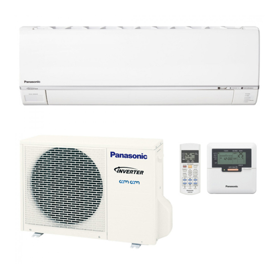
Indoor Unit
CS-E7PKEW
CS-E9PKEW
CS-E12PKEW
CS-E15PKEW
CS-E18PKEW
CS-E21PKEW
CS-E24PKEW
CS-XE7PKEW
CS-XE9PKEW
CS-XE12PKEW
CS-XE15PKEW
CS-XE18PKEW
CS-XE21PKEW
CS-E28PKES
Order No: PAPAMY1212045CE
Outdoor Unit
CU-E7PKE
CU-E9PKE
CU-E12PKE
CU-E15PKE
CU-E18PKE
CU-E21PKE
CU-E24PKE
CU-E7PKE
CU-E9PKE
CU-E12PKE
CU-E15PKE
CU-E18PKE
CU-E21PKE
CU-E28PKE
Destination
EU
E.Europe
L.America
New Zealand
Turkey
Croatia
S.Africa
© Panasonic Corporation 2012.
Advertisement
Table of Contents

Related Manuals for Panasonic CS-E7PKEW


Summary of Contents for Panasonic CS-E7PKEW
- Page 1 PRECAUTION OF LOW TEMPERATURE In order to avoid frostbite, be assured of no refrigerant leakage during the installation or repairing of refrigerant circuit. © Panasonic Corporation 2012.
- Page 2 CAUTION Before performing any of the electrical installation works, please verify on which of the intended connection use. Generally there are 2 types of indoor-outdoor connections: ○ Single Connection (Single Indoor Unit connects with Single Outdoor Unit) ○ Multiple Connection (Multiple Indoor Unit connect with Single Outdoor Unit) Both connections have different connecting methods.
-
Page 3: Table Of Contents
TABLE OF CONTENTS 13.12 In-filter Deactivation Operation....89 1. Safety Precautions..........4 13.13 Mild Dry Cooling Operation ......90 13.14 AUTO COMFORT and ECONAVI Operation. 2. Specifications .............6 ..............90 3. Features ............27 14. Operation Control (For Multi Split Connection) 4. Location of Controls and Components ..28 ................98 Indoor Unit..........28 14.1... -
Page 4: Safety Precautions
1. Safety Precautions • Read the following “SAFETY PRECAUTIONS” carefully before perform any servicing. • Electrical work must be installed or serviced by a licensed electrician. Be sure to use the correct rating of the power plug and main circuit for the model installed. •... - Page 5 WARNING During pump down operation, stop the compressor before remove the refrigeration piping. (Removal of compressor while compressor is operating and valves are opened will cause suck-in of air, abnormal high pressure in refrigeration cycle and result in explosion, injury etc.) After completion of installation or service, confirm there is no leakage or refrigerant gas.
-
Page 6: Specifications
2. Specifications Indoor CS-E7PKEW, CS-XE7PKEW CS-E9PKEW, CS-XE9PKEW Model Outdoor CU-E7PKE CU-E9PKE Performance Test Condition EUROVENT EUROVENT Phase, Hz Single, 50 Single, 50 Power Supply Min. Mid. Max. Min. Mid. Max. 0.75 2.05 2.40 0.85 2.50 3.00 Capacity BTU/h 2560 6990... - Page 7 Indoor CS-E7PKEW, CS-XE7PKEW CS-E9PKEW, CS-XE9PKEW Model Outdoor CU-E7PKE CU-E9PKE Type Hermetic Motor (Rotary) Hermetic Motor (Rotary) Compressor Motor Type Brushless (6 poles) Brushless (6 poles) Output Power Type Cross-Flow Fan Cross-Flow Fan Material ASG33 ASG33 Motor Type DC / Transistor (8-poles)
- Page 8 Indoor CS-E7PKEW, CS-XE7PKEW CS-E9PKEW, CS-XE9PKEW Model Outdoor CU-E7PKE CU-E9PKE Pipe Diameter (Liquid / Gas) mm (inch) 6.35 (1/4) / 9.52 (3/8) 6.35 (1/4) / 9.52 (3/8) Standard length m (ft) 5.0 (16.4) 5.0 (16.4) Length range (min – max) m (ft) 3 (9.8) ~ 15 (49.2)
- Page 9 Indoor CS-E12PKEW, CS-XE12PKEW CS-E15PKEW, CS-XE15PKEW Model Outdoor CU-E12PKE CU-E15PKE Performance Test Condition EUROVENT EUROVENT Phase, Hz Single, 50 Single, 50 Power Supply Min. Mid. Max. Min. Mid. Max. 0.85 3.50 4.00 0.85 4.20 5.00 Capacity BTU/h 2900 11900 13600 2900 14300 17100 Kcal/h...
- Page 10 Indoor CS-E12PKEW, CS-XE12PKEW CS-E15PKEW, CS-XE15PKEW Model Outdoor CU-E12PKE CU-E15PKE Type Hermetic Motor (Rotary) Hermetic Motor (Rotary) Compressor Motor Type Brushless (6 poles) Brushless (6 poles) Output Power Type Cross-Flow Fan Cross-Flow Fan Material ASG33 ASG33 Motor Type DC / Transistor (8-poles) DC / Transistor (8-poles) Input Power 44.9...
- Page 11 Indoor CS-E12PKEW, CS-XE12PKEW CS-E15PKEW, CS-XE15PKEW Model Outdoor CU-E12PKE CU-E15PKE Pipe Diameter (Liquid / Gas) mm (inch) 6.35 (1/4) / 9.52 (3/8) 6.35 (1/4) / 12.70 (1/2) Standard length m (ft) 5.0 (16.4) 5.0 (16.4) Length range (min – max) m (ft) 3 (9.8) ~ 15 (49.2) 3 (9.8) ~ 15 (49.2) I/D &...
- Page 12 Indoor CS-E18PKEW, CS-XE18PKEW CS-E21PKEW, CS-XE21PKEW Model Outdoor CU-E18PKE CU-E21PKE Performance Test Condition EUROVENT EUROVENT Phase, Hz Single, 50 Single, 50 Power Supply Min. Mid. Max. Min. Mid. Max. 0.98 5.00 6.00 0.98 6.30 7.10 Capacity BTU/h 3340 17100 20500 3340 21500 24200 Kcal/h...
- Page 13 Indoor CS-E18PKEW, CS-XE18PKEW CS-E21PKEW, CS-XE21PKEW Model Outdoor CU-E18PKE CU-E21PKE Type Hermetic Motor (Rotary) Hermetic Motor (Rotary) Compressor Motor Type Brushless (4 poles) Brushless (4 poles) Output Power Type Cross-Flow Fan Cross-Flow Fan Material ASG33 ASG33 Motor Type DC / Transistor (8-poles) DC / Transistor (8-poles) Input Power 80.0...
- Page 14 Indoor CS-E18PKEW, CS-XE18PKEW CS-E21PKEW, CS-XE21PKEW Model Outdoor CU-E18PKE CU-E21PKE Pipe Diameter (Liquid / Gas) mm (inch) 6.35 (1/4) / 12.70 (1/2) 6.35 (1/4) / 12.70 (1/2) Standard length m (ft) 5.0 (16.4) 5.0 (16.4) Length range (min – max) m (ft) 3 (9.8) ~ 20 (65.6) 3 (9.8) ~ 20 (65.6) I/D &...
- Page 15 Indoor CS-E24PKEW CS-E28PKES Model Outdoor CU-E24PKE CU-E28PKE Performance Test Condition EUROVENT EUROVENT Phase, Hz Single, 50 Single, 50 Power Supply Min. Mid. Max. Min. Mid. Max. 0.98 6.80 8.10 0.98 7.65 8.60 Capacity BTU/h 3340 23200 27600 3340 26100 29300 Kcal/h 5850 6970...
- Page 16 Indoor CS-E24PKEW CS-E28PKES Model Outdoor CU-E24PKE CU-E28PKE Type Hermetic Motor (Rotary) Hermetic Motor (Rotary) Compressor Motor Type Brushless (4 poles) Brushless (4 poles) Output Power 1.7k 1.7k Type Cross-Flow Fan Cross-Flow Fan Material ASG33 ASG33 Motor Type DC / Transistor (8-poles) DC / Transistor (8-poles) Input Power 104.0...
- Page 17 Indoor CS-E24PKEW CS-E28PKES Model Outdoor CU-E24PKE CU-E28PKE Pipe Diameter (Liquid / Gas) mm (inch) 6.35 (1/4) / 15.88 (5/8) 6.35 (1/4) / 15.88 (5/8) Standard length m (ft) 5.0 (16.4) 5.0 (16.4) Length range (min – max) m (ft) 3 (9.8) ~ 30 (98.4) 3 (9.8) ~ 30 (98.4) I/D &...
- Page 18 4.0kW to 5.6kW) 1) Two CS-E7PKEW only. (Total nominal cooling capacity is 4.0kW) 2) One CS-E7PKEW and one CS-E9PKEW. (Total nominal cooling capacity is 4.5kW) Remarks for CU-3E18PBE / CU-4E23PBE / CU-4E27PBE 1. At least two indoor units must be connected.
- Page 19 • Indoor Unit : CS-E7/9/12PKEW • Outdoor Unit : CU-2E15PBE 2Room 1Room Indoor Unit Capacity (kW) Total Indoor Capacity (kW) Indoor Unit Capacity (kW) Total Indoor Capacity (kW) 16+16 16+20 16+25 16+28 16+32 20+20 20+25 20+28 20+32 25+25 25+28 • Indoor Unit : CS-E7/9/12PKEW •...
- Page 20 • Indoor Unit : CS-E7/9/12/15/18PKEW • Outdoor Unit : CU-3E18PBE 3Room 2Room 1Room Indoor Unit Total Indoor Indoor Unit Total Indoor Indoor Unit Total Indoor Capacity (kW) Capacity (kW) Capacity (kW) Capacity (kW) Capacity (kW) Capacity (kW) 16+16+16 16+32 16+16+20 16+40 16+16+25 16+50...
- Page 21 • Indoor Unit : CS-E7/9/12/15/18PKEW • Outdoor Unit : CU-4E23PBE 4Room 3Room 2Room 1Room Indoor Unit Total Indoor Indoor Unit Total Indoor Indoor Unit Total Indoor Indoor Unit Total Indoor Capacity (kW) Capacity (kW) Capacity (kW) Capacity (kW) Capacity (kW) Capacity (kW) Capacity (kW) Capacity (kW)
- Page 22 20+25+28+32 28+28+32 20+25+32+32 28+28+40 20+28+28+28 28+28+50 20+28+28+32 28+32+32 25+25+25+25 28+32+40 25+25+25+28 28+32+50 25+25+25+32 28+40+40 25+25+28+28 32+32+32 25+25+28+32 32+32+40 25+28+28+28 • Indoor Unit : CS-E7/9/12/15/18/21/24PKEW • Outdoor Unit : CU-4E27PBE 4Room 3Room 2Room 1Room Indoor Unit Total Indoor Indoor Unit Total Indoor Indoor Unit Total Indoor Indoor Unit...
- Page 23 25+25+25+50 28+28+50 25+25+25+60 28+28+60 25+25+28+28 28+28+70 25+25+28+32 28+32+32 25+25+28+40 28+32+40 25+25+28+50 28+32+50 25+25+32+32 28+32+60 25+25+32+40 28+32+70 25+25+32+50 28+40+40 25+25+40+40 28+40+50 25+28+28+28 28+40+60 25+28+28+32 28+50+50 25+28+28+40 32+32+32 25+28+28+50 32+32+40 25+28+32+32 32+32+50 25+28+32+40 32+32+60 25+28+32+50 32+32+70 25+28+40+40 32+40+40 25+32+32+32 32+40+50 25+32+32+40 32+40+60 28+28+28+28 32+50+50 28+28+28+32...
- Page 24 20+20+25+25+50 20+25+25+28 25+25+25 20+20+25+25+60 20+25+25+32 25+25+28 20+20+25+25+70 20+25+25+40 25+25+32 20+20+25+28+28 20+25+25+50 25+25+40 20+20+25+28+32 20+25+25+60 25+25+50 20+20+25+28+40 20+25+25+70 25+25+60 20+20+25+28+50 20+25+28+28 25+25+70 20+20+25+28+60 20+25+28+32 25+28+28 20+20+25+28+70 20+25+28+40 25+28+32 20+20+25+32+32 20+25+28+50 25+28+40 20+20+25+32+40 20+25+28+60 25+28+50 20+20+25+32+50 20+25+28+70 25+28+60 20+20+25+32+60 20+25+32+32 25+28+70 20+20+25+32+70 20+25+32+40 25+32+32 20+20+25+40+40...
- Page 25 20+25+28+32+60 25+25+28+70 20+25+28+32+70 25+25+32+32 20+25+28+40+40 25+25+32+40 20+25+28+40+50 25+25+32+50 20+25+28+40+60 25+25+32+60 20+25+28+50+50 25+25+32+70 20+25+32+32+32 25+25+40+40 20+25+32+32+40 25+25+40+50 20+25+32+32+50 25+25+40+60 20+25+32+32+60 25+25+40+70 20+25+32+40+40 25+25+50+50 20+25+32+40+50 25+25+50+60 20+25+40+40+40 25+25+50+70 20+25+40+40+50 25+25+60+60 20+28+28+28+28 25+28+28+28 20+28+28+28+32 25+28+28+32 20+28+28+28+40 25+28+28+40 20+28+28+28+50 25+28+28+50 20+28+28+28+60 25+28+28+60 20+28+28+28+70 25+28+28+70 20+28+28+32+32 25+28+32+32 20+28+28+32+40...
- Page 26 25+25+40+40+40 28+32+50+50 25+28+28+28+28 28+32+50+60 25+28+28+28+32 28+40+40+40 25+28+28+28+40 28+40+40+50 25+28+28+28+50 28+40+40+60 25+28+28+28+60 28+40+50+50 25+28+28+32+32 32+32+32+32 25+28+28+32+40 32+32+32+40 25+28+28+32+50 32+32+32+50 25+28+28+32+60 32+32+32+60 25+28+28+40+40 32+32+32+70 25+28+28+40+50 32+32+40+40 25+28+32+32+32 32+32+40+50 25+28+32+32+40 32+32+40+60 25+28+32+32+50 32+32+40+70 25+28+32+40+40 32+32+50+50 25+28+32+40+50 32+32+50+60 25+28+40+40+40 32+40+40+40 25+32+32+32+32 32+40+40+50 25+32+32+32+40 32+40+40+60 25+32+32+32+50 32+40+50+50 25+32+32+40+40...
-
Page 27: Features
Features • Inverter Technology Wider output power range Energy saving Quick Cooling Quick Heating More precise temperature control • Environment Protection Non-ozone depletion substances refrigerant (R410A) • Long Installation Piping Long piping up to 15 meters (0.75 ~ 1.75HP) and 20 meters (2.0 ~ 2.25HP) during single split connection only CS/CU-E24/28PK, long piping up to 30 meter •... -
Page 28: Location Of Controls And Components
4. Location of Controls and Components Indoor Unit Outdoor Unit Remote Control... -
Page 29: Dimensions
5. Dimensions Indoor Unit 5.1.1 CS-E7PK CS-E9PK CS-E12PK CS-E15PK CS-XE7PK CS-XE9PK CS-XE12PK CS-XE15PK... - Page 30 5.1.2 CS-E18PK CS-E21PK CS-E24PK CS-E28PK CS-XE18PK CS-XE21PK...
-
Page 31: Outdoor Unit
Outdoor Unit 5.2.1 CU-E7PKE CU-E9PKE 5.2.2 CU-E12PKE CU-E15PKE... - Page 32 5.2.3 CU-E18PKE CU-E21PKE...
- Page 33 5.2.4 CU-E24PKE CU-E28PKE...
-
Page 34: Refrigeration Cycle Diagram
6. Refrigeration Cycle Diagram CU-E7PKE CU-E9PKE CU-E12PKE CU-E15PKE INDOOR OUTDOOR LIQUID EXPANSION SIDE VALVE MUFFLER STRAINER 2-WAY VALVE INTAKE TEMP. PIPE SENSOR TEMP. CONDENSER SENSOR HEAT EXCHANGER (EVAPORATOR) SIDE 4-WAYS VALVE 3-WAY MUFFLER VALVE COMPRESSOR COOLING HEATING... -
Page 35: Cu-E18Pke Cu-E21Pke
CU-E18PKE CU-E21PKE INDOOR OUTDOOR LIQUID EXPANSION SIDE VALVE STRAINER 2-WAY PROCESS VALVE TUBE TEMP. SENSOR CONDENSER INTAKE TEMP. PIPE SENSOR TEMP. SENSOR PIPE TEMP. SENSOR HEAT EXCHANGER DIS. TEMP. (EVAPORATOR) SENSOR SIDE 4-WAYS VALVE OIL SEPERATOR 3-WAY (E21PKE only) VALVE TANK SENSOR COMPRESSOR... -
Page 36: Cu-E24Pke Cu-E28Pke
CU-E24PKE CU-E28PKE INDOOR OUTDOOR LIQUID SIDE RECEIVER STRAINER STRAINER EXPANSION 2-WAY VALVE VALVE INTAKE F. COND. TEMP. SENSOR PIPE TEMP. DISTRIBUTOR SENSOR HEAT EXCHANGER (EVAPORATOR) PROCESS TUBE SIDE 4-WAYS VALVE DISCHARGE 3-WAY MUFFLER VALVE COMPRESSOR COOLING HEATING... -
Page 37: Block Diagram
7. Block Diagram CU-E7PKE... -
Page 38: Cu-E9Pke Cu-E12Pke Cu-E15Pke
CU-E9PKE CU-E12PKE CU-E15PKE... -
Page 39: Cu-E18Pke Cu-E21Pke
CU-E18PKE CU-E21PKE... -
Page 40: Cu-E24Pke Cu-E28Pke
CU-E24PKE CU-E28PKE... -
Page 41: Wiring Connection Diagram
8. Wiring Connection Diagram Indoor Unit 8.1.1 CS-E7PK CS-E9PK CS-E12PK CS-E15PK CS-E18PK CS-E21PK CS-E24PK CS-XE7PK CS-XE9PK CS-XE12PK CS-XE15PK CS-XE18PK CS-XE21PK... - Page 42 8.1.2 CS-E28PKES...
-
Page 43: Outdoor Unit
Outdoor Unit 8.2.1 CU-E7PKE Resistance of Compressor Windings MODEL CU-E7PKE CONNECTION 5RS092XCD21 (Ω) 1.152 1.152 1.152 Note: Resistance at 20°C of ambient temperature. - Page 44 8.2.2 CU-E9PKE CU-E12PKE CU-E15PKE Resistance of Compressor Windings Resistance of Compressor Windings MODEL CU-E9PKE MODEL CU-E12PKE / CU-E15PKE CONNECTION 5RS102XBC21 (Ω) CONNECTION 5RS102XNA21 (Ω) 0.858 1.211 0.858 1.211 0.858 1.211 Note: Resistance at 20°C of ambient temperature. Note: Resistance at 20°C of ambient temperature.
- Page 45 8.2.3 CU-E18PKE CU-E21PKE Resistance of Compressor Windings MODEL CU-E18PKE / CU-E21PKE CONNECTION 5RD102XBA21 (Ω) 1.897 1.907 1.882 Note: Resistance at 20°C of ambient temperature.
- Page 46 8.2.4 CU-E24PKE Resistance of Compressor Windings MODEL CU-E24PKE CONNECTION 5KD240XAF21 (Ω) 0.720 0.726 0.708 Note: Resistance at 20°C of ambient temperature.
- Page 47 8.2.5 CU-E28PKE Resistance of Compressor Windings MODEL CU-E28PKE CONNECTION 5KD240XAF21 (Ω) 0.720 0.726 0.708 Note: Resistance at 20°C of ambient temperature.
-
Page 48: Electronic Circuit Diagram
9. Electronic Circuit Diagram Indoor Unit... -
Page 49: Outdoor Unit
Outdoor Unit 9.2.1 CU-E7PKE TO INDOOR UNIT ELECTRO-MAGNETIC COIL (EXPANSION VALVE) REACTOR TERMINAL (BLACK) (WHITE) (RED) BOARD RAT2 RAT1 CN-STM (GRY) (GRY) (WHT) 15.8k 15.0k OUTDOOR TEMP. 1µ 1µ SENSOR (15kΩ 3950) DATA (RED) COMMUNICATION PIPE TEMP. CIRCUIT SENSOR1 (4.96kΩ 3800) AC-BLK (BLK) CIRCUIT... - Page 50 9.2.2 CU-E9PKE CU-E12PKE CU-E15PKE TO INDOOR UNIT REACTOR TERMINAL (BLACK) (WHITE) (RED) BOARD RAT2 RAT1 (GRY) (GRY) C190 0.1µ IC12 ELECTRONIC EXPANSION CONTROLLER VALVE CN-STM FUSE104 15.8k 15.0k (15A 250V) DATA IC19 (RED) OUTDOOR TEMP. 1µ 1µ SENSOR (15kΩ 3950) NOISE FILTER AC-BLK...
- Page 51 9.2.3 CU-E18PKE CU-E21PKE TO INDOOR UNIT REACTOR TERMINAL (BLK) (WHT) (RED) BOARD L2-I L2-O (GRAY) (GRAY) COMP. TEMP. SENSOR R410 1µ 4.99k (THERMISTOR) COM3 (RED) (50kΩ 3950) COMMUNICATION OUTDOOR A R TEMP. CIRCUIT SENSOR R101 R100 (THERMISTOR) 15.8k 15.0k AC-BLK (15kΩ...
- Page 52 9.2.4 CU-E24PKE REACTOR REACTOR L1-I L2-I L1-O L2-O ACL1 CN-BLK AC-BLK (GREEN) (BLACK) (GRAY) (GRAY) (BLACK) (BLACK) (BLACK) (BLACK) TERM NAL NOISE FILTER FUSE3 CN-WHT AC-WHT BOARD (RED) (25A 250V) (WHITE) (WHITE) CIRCUIT (BLU) ACN1 (YELLOW) (WHITE) COMMUNICATION FUSE2 COMPRESSOR CIRCUIT COM3 T3.15A...
-
Page 53: Noise Filter
9.2.5 CU-E28PKE THERMAL REACTOR PROTECTOR 150°C REACTOR L1-I L2-I L2-O L2-O ACL1 CN-BLK AC-BLK *CN-RY1 (BLACK) (GREEN) (GRAY) (GRAY) (BLACK) (BLACK) (BLACK) (BLACK) TERMINAL NOISE FILTER FUSE3 CN-WHT AC-WHT BOARD (25A 250V) (WHITE) (WHITE) C RCUIT RY-PWR2 ACN1 *JP1 (WHITE) COMMUNICATION FUSE2 C RCUIT... -
Page 54: Printed Circuit Board
10. Printed Circuit Board 10.1 Indoor Unit 10.1.1 Main Printed Circuit Board 10.1.2 Indicator Printed Circuit Board... - Page 55 10.1.3 Receiver Printed Circuit Board 10.1.4 High Voltage Power Supply Printed Circuit Board 10.1.5 Fuse Printed Circuit Board...
- Page 56 10.1.6 Human Activity Sensor Printed Circuit Board...
-
Page 57: Outdoor Unit
10.2 Outdoor Unit 10.2.1 CU-E7PKE... - Page 58 10.2.2 CU-E9PKE CU-E12PKE CU-E15PKE...
- Page 59 10.2.3 CU-E18PKE CU-E21PKE...
- Page 60 10.2.4 CU-E24PKE CU-E28PKE...
-
Page 61: Installation Instruction
11. Installation Instruction 11.1 Select the Best Location 11.1.3 Indoor/Outdoor Unit Installation Diagram 11.1.1 Indoor Unit • Do not install the unit in excessive oil fume area such as kitchen, workshop and etc. • There should not be any heat source or steam near the unit. -
Page 62: Indoor Unit
11.2 Indoor Unit The mounting wall shall be strong and solid enough to prevent it from vibration. Dimension Model E7***, E9***, E12***, E15*** 490 mm 82 mm 439 mm 432 mm 43 mm 95 mm XE7***, XE9***, XE12***, XE15*** E18***, E21***, E24*** 590 mm 82 mm 539 mm... - Page 63 11.2.2 Indoor Unit Installation 11.2.2.1 For the right rear piping 11.2.2.2 For the right and right bottom piping 11.2.2.3 For the embedded piping (This can be used for left rear piping and bottom piping also.)
- Page 64 11.2.3 Connect the Cable to the Indoor Unit The power supply cord, indoor and outdoor unit connection cable can be connected without removing the front grille. Install the indoor unit on the installing holder that mounted on the wall. Open the front panel and grille door by loosening the screw. Cable connection to the power supply through Isolating Devices (Disconnecting means).
- Page 65 Remove the tapes and connect the power supply cord and connection cable between indoor unit and outdoor unit according to the diagram below. Secure the power supply cord and connection cable onto the control board with the holder. Close grille door by tighten with screw and close the front panel. Note: •...
-
Page 67: Outdoor Unit
11.3 Outdoor Unit 11.3.1 Install the Outdoor Unit • After selecting the best location, start installation according to Indoor/Outdoor Unit Installation Diagram. Fix the unit on concrete or rigid frame firmly and horizontally by bolt nut (ø10 mm). When installing at roof, please consider strong wind and earthquake. Please fasten the installation stand firmly with bolt or nails. - Page 68 * For Gas side piping please refer table and diagram below...
- Page 69 11.3.3 Evacuation of the Equipment WHEN INSTALLING AN AIR CONDITIONER, BE SURE TO EVACUATE THE AIR INSIDE THE INDOOR UNIT AND PIPES in the following procedure. Connect a charging hose with a push pin to the Low side of a charging set and the service port of the 3-way valve.
- Page 70 11.3.4 Connect the cable to the Outdoor Unit Remove the control board cover from the unit by loosening the screw. Connection cable between indoor unit and outdoor unit shall be approved polychloroprene sheathed 4 × 1.5 (3/4 ~ 1.75HP) or 4 × 2.5 mm (2.0 ~ 2.5HP) flexible cord, type designation 60245 IEC 57 or heavier cord.
-
Page 71: Installation Instruction
12. Installation Instruction (CS-E28PKES CU-E28PKE only) 12.1.3 Indoor/Outdoor Unit Installation 12.1 Select the Best Location Diagram 12.1.1 Indoor Unit • Do not install the unit in excessive oil fume area such as kitchen, workshop and etc. • There should not be any heat source or steam near the unit. -
Page 72: Indoor Unit
12.2 Indoor Unit The mounting wall shall be strong and solid enough to prevent it from vibration. Dimension Model E28*** 590 mm 82 mm 539 mm 532 mm 169 mm 219 mm ○ The centre of installation plate should be at more than 1 at right and left of the wall. - Page 73 12.2.2 Indoor Unit Installation 12.2.2.1 For the right rear piping 12.2.2.2 For the right and right bottom piping 12.2.2.3 For the embedded piping (This can be used for left rear piping and bottom piping also.)
- Page 74 12.2.3 Connect the Cable to the Indoor Unit The power supply cord, indoor and outdoor unit connection cable can be connected without removing the front grille. Install the indoor unit on the installing holder that mounted on the wall. Open the front panel and grille door by loosening the screw. Cable connection to the power supply through Isolating Devices (Disconnecting means).
- Page 75 Remove the tapes and connect the power supply cord and connection cable between indoor unit and outdoor unit according to the diagram below. Secure the power supply cord and connection cable onto the control board with the holder. Close grille door by tighten with screw and close the front panel. Note: •...
-
Page 77: Outdoor Unit
12.3 Outdoor Unit 12.3.1 Install the Outdoor Unit • After selecting the best location, start installation according to Indoor/Outdoor Unit Installation Diagram. Fix the unit on concrete or rigid frame firmly and horizontally by bolt nut (ø10 mm). When installing at roof, please consider strong wind and earthquake. Please fasten the installation stand firmly with bolt or nails. - Page 78 12.3.3 Evacuation of the Equipment WHEN INSTALLING AN AIR CONDITIONER, BE SURE TO EVACUATE THE AIR INSIDE THE INDOOR UNIT AND PIPES in the following procedure. Connect a charging hose with a push pin to the Low side of a charging set and the service port of the 3-way valve.
- Page 79 12.3.4 Connect the cable to the Outdoor Unit Remove the control board cover from the unit by loosening the screw. Connection cable between indoor unit and outdoor unit shall be approved polychloroprene sheathed 4 × 4.0 (3.0HP) flexible cord, type designation 60245 IEC 57 or heavier cord. Do not use joint connection cable. Replace the wire if the existing wire (from concealed wiring, or otherwise) is too short.
-
Page 80: Operation Control
13. Operation Control 13.1 Basic Function Inverter control, which equipped with a microcomputer in determining the most suitable operating mode as time passes, automatically adjusts output power for maximum comfort always. In order to achieve the suitable operating mode, the microcomputer maintains the set temperature by measuring the temperature of the environment and performing temperature shifting. -
Page 81: Indoor Fan Motor Operation
13.1.5 Automatic Operation • This mode can be set using remote control and the operation is decided by remote control setting temperature, remote control operation mode and indoor intake air temperature. • During operation mode judgment, indoor fan motor (with speed of Lo-) is running for 30 seconds to detect the indoor intake air temperature. -
Page 82: Outdoor Fan Motor Operation
[Heating] • According to indoor pipe temperature, automatic heating fan speed is determined as follows. B. Feedback control • Immediately after the fan motor started, feedback control is performed once every second. • During fan motor on, if fan motor feedback ≥ 2550 rpm or < 50 rpm continue for 10 seconds, then fan motor error counter increase, fan motor is then stop and restart. -
Page 83: Airflow Direction
Control of airflow direction can be automatic (angles of direction is determined by operation mode, heat exchanger temperature and intake air temperature) and manual (angles of direction can be adjusted using remote control). 13.4.1 Vertical Airflow CS-E7PKEW CS-E9PKEW CS-E12PKEW CS-E15PKEW Upper Vane Angle (°) Lower Vane Angle (°) Operation Mode Airflow Direction... -
Page 84: Quiet Operation (Cooling Mode/Cooling Area Of Dry Mode)
13.4.2 Horizontal Airflow • Automatic horizontal airflow direction can be set using remote control; the vane swings left and right within the angles as stated below. For heating mode operation, the angle of the vane depends on the indoor heat exchanger temperature as Figure 1 below. -
Page 85: Quiet Operation (Heating)
• Control contents Fan speed is changed from normal setting to quiet setting of respective fan speed. Fan speed for quiet operation is reduced from setting fan speed. 13.6 Quiet operation (Heating) • Purpose To provide quiet heating operation compare to normal operation. •... -
Page 86: Timer Control
13.8 Timer Control • There are 2 sets of ON and OFF timer available to turn the unit ON or OFF at different preset time. • If more than one timer had been set, the upcoming timer will be displayed and will activate in sequence. 13.8.1 ON Timer Control •... -
Page 87: Nanoe-G Operation
13.11 nanoe-G Operation • This operation provides clean air by producing great amount of negative ions and distribute through the discharge airflow to capture or deactivate molds, bacteria or viruses. • nanoe-G operation start condition During unit running at any operation mode, if nanoe-G operation is activated, combination operation (operation mode + nanoe-G operation) starts. - Page 88 • nanoe-G check mode To enable nanoe-G check mode, during nanoe-G operation ON: If there is abnormal discharge, nanoe-G indicator blinks immediately. • Error detection control When nanoe-G indicator blinks, it indicates error listed below: nanoe-G connector at main PCB open Judgment method •...
-
Page 89: In-Filter Deactivation Operation
nanoe-G breakdown error Judgment method • Hi-feedback voltage (at microcontroller) supplied to the nanoe-G system when nanoe-G operation is OFF; nanoe-G breakdown error show immediately. • It is due to indoor PCB or nanoe-G high voltage power supply damage. • Operations except nanoe-G continue. -
Page 90: Mild Dry Cooling Operation
13.13 Mild Dry Cooling Operation • This operation helps to prevent decreases in room humidity while maintaining the setting temperature. • During unit running at Cooling operation mode, if “Mild Dry Cooling” button is pressed, Mild Dry Cooling operation starts and Mild Dry Cooling indicators turns ON at remote control display. •... - Page 91 13.14.1 Human Activity Sensor Area of human availability, activity level and absent is judged based on pulses by using infrared sensor. The internal setting temperature shift, fan speed and horizontal airflow direction are adjusted in order to provide comfort environment while maintain the energy saving level. ...
- Page 92 13.14.1.2 Information Log • The signal from Infrared sensors will be log to human activity database for further analysis. 13.14.1.3 Human Position Analysis • According to Area of Living, frequency of activity, the system will analyze the human position away from the indoor unit.
- Page 93 13.14.1.9 Rhythmic Temperature Wave Operation • To further maximize the energy saving during ECONAVI or AUTO COMFORT operates at low activity level. • Start condition The unit is operates in Cool or Dry mode under ECONAVI or AUTO COMFORT operation, and Human activity sensor detects low activity level, and Neuro stable zone continuously for 60 minutes.
- Page 94 13.14.1.10 ECONAVI and AUTO COMFORT Demo Mode • To enable ECO DEMO mode: • To disable ECO Demo MODE: Transmit ECO Demo signal again. 13.14.1.11 Human Activity Sensor Abnormality • Abnormality detection: Connector disconnection / Wire cut abnormality o Sensor judge Hi level continuously for 25 seconds Circuit abnormality o 70 seconds after power ON, if human activity sensor judge Lo level continuously for 25 seconds •...
- Page 95 13.14.1.12 Human Activity Sensor Check Mode • To enable human activity sensor abnormality check mode: • During ECONAVI is ON, when CHECK signal received, if either sensors has abnormality, the 4 times abnormality counter is ignored, ECONAVI Indicator will blink immediately and error code is memorized. •...
- Page 96 13.14.2.2 Judge Sunlight Intensity • Based on sunlight sensor output voltage, the sunlight intensity value will be computed and logged to sunlight intensity database. • The sunlight sensor sensitivity could be adjusted: 13.14.2.3 Judge Ambient Condition • According to sunlight intensity over a period of time, the system will analyze the ambient condition is sunny, cloudy or night.
- Page 97 13.14.2.5 Sunlight Sensor Check Mode • To enable sunlight sensor check mode, during unit is OFF (power standby): • Operation details The sunlight sensor check mode will be operated for 5 minutes. During check mode, the ON and OFF timer will be memorized but it operation be ignored. During check mode, if the sunlight sensor check code is retransmitted, the 5 minutes counter will be reset.
-
Page 98: Operation Control (For Multi Split Connection)
14. Operation Control (For Multi Split Connection) During multi split connection, indoor unit’s operation controls are same with single split connection unless specified in this chapter. 14.1 Cooling operation 14.1.1 Thermostat control • Capability supply to indoor unit is OFF (Expansion valve closed) when Intake Air Temperature — Internal setting temperature <... -
Page 99: Automatic Operation
14.4 Automatic Operation • This mode can be set using remote control and the operation is decided by remote control setting temperature, remote control operation mode, indoor intake and outdoor air temperature. • During operation mode judgment, indoor fan motor (with speed of -Lo) and outdoor fan motor are running for 30 seconds to detect the indoor intake and outdoor air temperature. -
Page 100: Protection Control
15. Protection Control 15.1 Protection Control For All Operations 15.1.1 Restart Control (Time Delay Safety Control) • The Compressor will not turn on within 3 minutes from the moment operation stops, although the unit is turned on again by pressing OFF/ON button at remote control within this period. •... - Page 101 15.1.4 Compressor Overheating Prevention Control • Instructed frequency for compressor operation will be regulated by compressor discharge temperature. The changes of frequency are as below. • If compressor discharge temperature exceeds 107°C, compressor will be stopped, occurs 4 times per 20 minutes, timer LED will be blinking.
-
Page 102: Protection Control For Cooling & Soft Dry Operation
15.2 Protection Control For Cooling & Soft Dry Operation 15.2.1 Outdoor Air Temperature Control • The compressor operating frequency is regulated in accordance to the outdoor air temperature as shown in the diagram below. • This control will begin 1 minute after the compressor starts. •... -
Page 103: Odor Cut Control
15.2.6 Odor Cut Control • To reduce the odor released from the unit. Start Condition AUTO FAN Speed is selected during COOL or DRY operation. During freeze prevention control and timer preliminary operation, this control is not applicable. Control content Depends on compressor conditions: 1. -
Page 104: Servicing Mode
16. Servicing Mode 16.1 Auto OFF/ON Button AUTO OPERATION MODE The Auto operation will be activated immediately once the Auto OFF/ON button is pressed. This operation can be used to operate air conditioner with limited function if remote control is misplaced or malfunction. TEST RUN OPERATION (FOR PUMP DOWN/SERVICING PURPOSE) The Test Run operation will be activated if the Auto OFF/ON button is pressed continuously for more than 5 seconds. -
Page 105: Remote Control Button
REMOTE CONTROL RECEIVING SOUND OFF/ON MODE The Remote Control Receiving Sound OFF/ON Mode will be activated if the Auto OFF/ON button is pressed continuously for more than 16 seconds (4 “beep” sounds will occur at 16th seconds to identify the Remote Control Receiving Sound Off/On Mode is in standby condition) and press “AC Reset”... -
Page 106: Troubleshooting Guide
17. Troubleshooting Guide 17.1 Refrigeration Cycle System In order to diagnose malfunctions, make sure that there are no Normal Pressure and Outlet Air Temperature (Standard) electrical problems before inspecting the refrigeration cycle. Gas Pressure Outlet air Temperature Such problems include insufficient insulation, problem with the (kg/cm (°C) power source, malfunction of a compressor and a fan. - Page 107 17.1.1 Relationship between the condition of the air conditioner and pressure and electric current Cooling Mode Heating Mode Condition of the Electric current Electric current air conditioner Low Pressure High Pressure Low Pressure High Pressure during operation during operation Insufficient refrigerant (gas leakage) Clogged capillary tube or Strainer...
-
Page 108: Breakdown Self Diagnosis Function
17.2 Breakdown Self Diagnosis Function 17.2.1 Self Diagnosis Function (Three Digits Alphanumeric Code) • When the latest abnormality code on the main Once abnormality has occurred during operation, unit and code transmitted from the remote the unit will stop its operation, and Timer LED controller are matched, power LED will light blinks. -
Page 109: Error Codes Table
17.3 Error Codes Table Diagnosis Abnormality / Abnormality Protection Problem Check location display Protection control Judgment Operation No memory of failure — Normal operation — — Indoor fan only • Indoor/outdoor wire terminal Indoor/outdoor operation can Indoor/outdoor After operation for •... - Page 110 Diagnosis Abnormality / Abnormality Protection Problem Check location display Protection control Judgment Operation • Check indoor/outdoor Wrong wiring and connection wire and connection Abnormal wiring or — — connecting pipe, expansion pipe piping connection valve abnormality • Expansion valve and lead wire and connector •...
-
Page 111: Self-Diagnosis Method
17.4 Self-diagnosis Method 17.4.1 H11 (Indoor/Outdoor Abnormal Communication) Malfunction Decision Conditions • During startup and operation of cooling and heating, the data received from outdoor unit in indoor unit signal transmission is checked whether it is normal. Malfunction Caused • Faulty indoor unit PCB. - Page 112 17.4.2 H12 (Indoor/Outdoor Capacity Rank Mismatched) Malfunction Decision Conditions • During startup, error code appears when different types of indoor and outdoor units are interconnected. Malfunction Caused • Wrong models interconnected. • Wrong indoor unit or outdoor unit PCBs mounted. •...
- Page 113 17.4.3 H14 (Indoor Intake Air Temperature Sensor Abnormality) Malfunction Decision Conditions • During startup and operation of cooling and heating, the temperatures detected by the indoor intake air temperature sensor are used to determine sensor errors. Malfunction Caused • Faulty connector connection. •...
- Page 114 17.4.4 H15 (Compressor Temperature Sensor Abnormality) Malfunction Decision Conditions • During startup and operation of cooling and heating, the temperatures detected by the outdoor compressor temperature sensor are used to determine sensor errors. Malfunction Caused • Faulty connector connection. • Faulty sensor.
- Page 115 17.4.5 H16 (Outdoor Current Transformer) Malfunction Decision Conditions • An input current, detected by Current Transformer CT, is below threshold value when the compressor is operating at certain frequency value for 3 minutes. Malfunction Caused • Lack of gas • Broken CT (current transformer) •...
- Page 116 17.4.6 H19 (Indoor Fan Motor – DC Motor Mechanism Locked) Malfunction Decision Conditions • The rotation speed detected by the Hall IC during fan motor operation is used to determine abnormal fan motor (feedback of rotation > 2550rpm or < 50rpm) Malfunction Caused •...
- Page 117 17.4.7 H23 (Indoor Pipe Temperature Sensor Abnormality) Malfunction Decision Conditions • During startup and operation of cooling and heating, the temperatures detected by the indoor heat exchanger temperature sensor are used to determine sensor errors. Malfunction Caused • Faulty connector connection. •...
- Page 118 17.4.8 H27 (Outdoor Air Temperature Sensor Abnormality) Malfunction Decision Conditions • During startup and operation of cooling and heating, the temperatures detected by the outdoor air temperature sensor are used to determine sensor errors. Malfunction Caused • Faulty connector connection. •...
- Page 119 17.4.9 H28 (Outdoor Pipe Temperature Sensor Abnormality) Malfunction Decision Conditions • During startup and operation of cooling and heating, the temperatures detected by the outdoor pipe temperature sensor are used to determine sensor errors. Malfunction Caused • Faulty connector connection. •...
- Page 120 17.4.10 H30 (Compressor Discharge Temperature Sensor Abnormality) Malfunction Decision Conditions • During startup and operation of cooling and heating, the temperatures detected by the outdoor discharge pipe temperature sensor are used to determine sensor errors. Malfunction Caused • Faulty connector connection. •...
- Page 121 17.4.11 H32 (Outdoor Heat Exchanger Temperature Sensor 2 Abnormality) Malfunction Decision Conditions • During startup and operation of cooling and heating, the temperatures detected by the outdoor heat exchanger temperature sensor are used to determine sensor errors. Malfunction Caused • Faulty connector connection.
- Page 122 17.4.12 H33 (Unspecified Voltage between Indoor and Outdoor) Malfunction Decision Conditions • The supply power is detected for its requirement by the indoor/outdoor transmission. Malfunction Caused • Wrong models interconnected. • Wrong indoor unit and outdoor unit PCBs used. • Indoor unit or outdoor unit PCB defective.
- Page 123 17.4.13 H34 (Outdoor Heat Sink Temperature Sensor Abnormality) Malfunction Decision Conditions • During startup and operation of cooling and heating, the temperatures detected by the outdoor heat sink temperature sensor are used to determine sensor errors. Malfunction Caused • Faulty connector connection. •...
- Page 124 17.4.14 H36 (Outdoor Gas Pipe Sensor Abnormality) Malfunction Decision Conditions • During startup and operation of cooling and heating, the temperatures detected by the outdoor gas pipe temperature sensor are used to determine sensor errors. Malfunction Caused • Faulty connector connection. •...
- Page 125 17.4.15 H37 (Outdoor Liquid Pipe Temperature Sensor Abnormality) Malfunction Decision Conditions • During startup and operation of cooling and heating, the temperatures detected by the outdoor liquid pipe temperature sensor are used to determine sensor errors. Malfunction Caused • Faulty connector connection. •...
- Page 126 17.4.16 H97 (Outdoor Fan Motor – DC Motor Mechanism Locked) Malfunction Decision Conditions • The rotation speed detected by the Hall IC during fan motor operation is used to determine abnormal fan motor. Malfunction Caused • Operation stops due to short circuit inside the fan motor winding. •...
- Page 127 17.4.17 H98 (Error Code Stored in Memory and no alarm is triggered / no TIMER LED flashing) Malfunction Decision Conditions • Indoor high pressure is detected when indoor heat exchanger is detecting very high temperature when the unit is operating in heating operation. •...
- Page 128 17.4.18 H99 (Indoor Freeze Prevention Protection: Cooling or Soft Dry) Error Code will not display (no Timer LED blinking) but store in EEPROM Malfunction Decision Conditions • Freeze prevention control takes place (when indoor pipe temperature is lower than 2°C) Malfunction Caused •...
- Page 129 17.4.19 F11 (4-way Valve Switching Failure) Malfunction Decision Conditions • When indoor heat exchanger is cold during heating (except deice) or when indoor heat exchanger is hot during cooling and compressor operating, the 4-way valve is detected as malfunction. Malfunction Caused •...
- Page 130 17.4.20 F17 (Indoor Standby Units Freezing Abnormality) Malfunction Decision Conditions • When the different between indoor intake air temperature and indoor pipe temperature is above 10°C or indoor pipe temperature is below -1.0°C. Remark: When the indoor standby unit is freezing, the outdoor unit transfers F17 error code to the corresponding indoor unit and H39 to other indoor unit(s).
- Page 131 17.4.21 F90 (Power Factor Correction Protection) Malfunction Decision Conditions • To maintain DC voltage level supply to power transistor. • To detect high DC voltage level after rectification. Malfunction Caused • During startup and operation of cooling and heating, when Power Factor Correction (PFC) protection circuitry at the outdoor unit main PCB senses abnormal DC voltage level for power transistors.
- Page 132 17.4.22 F91 (Refrigeration Cycle Abnormality) Malfunction Decision Conditions • The input current is low while the compressor is running at higher than the setting frequency. Malfunction Caused • Lack of gas. • 3-way valve close. Troubleshooting...
- Page 133 17.4.23 F93 (Compressor Rotation Failure) Malfunction Decision Conditions • A compressor rotation failure is detected by checking the compressor running condition through the position detection circuit. Malfunction Caused • Compressor terminal disconnect • Faulty Outdoor PCB • Faulty compressor Troubleshooting...
- Page 134 17.4.24 F95 (Outdoor High Pressure Protection: Cooling or Soft Dry) Malfunction Decision Conditions • During operation of cooling or soft dry, when outdoor unit heat exchanger high temperature data is detected by the outdoor unit heat exchanger thermistor. Malfunction Caused •...
- Page 135 17.4.25 F96 (IPM Overheating) Malfunction Decision Conditions • During operating of cooling and heating, when IPM temperature data (100°C) is detected by the IPM temperature sensor. Multi Models only Compressor Overheating: During operation of cooling and heating, when the compressor OL is activated. Heat Sink Overheating: During operation of cooling and heating, when heat sink temperature data (90°C) is detected by the heat sink temperature sensor.
- Page 136 17.4.26 F97 (Compressor Overheating) Malfunction Decision Conditions • During operation of cooling and heating, when compressor tank temperature data (112°C) is detected by the compressor tank temperature sensor. Malfunction Caused • Faulty compressor tank temperature sensor • 2/3 way valve closed •...
- Page 137 17.4.27 F98 (Input Over Current Detection) Malfunction Decision Conditions • During operation of cooling and heating, when an input over-current (X value in Total Running Current Control) is detected by checking the input current value being detected by current transformer (CT) with the compressor running.
- Page 138 17.4.28 F99 (DC Peak Detection) Malfunction Decision Conditions During startup and operation of cooling and heating, when inverter DC peak data is received by the outdoor internal DC Peak sensing circuitry. Malfunction Caused • DC current peak due to compressor failure. •...
-
Page 139: Disassembly And Assembly Instructions
18. Disassembly and Assembly Instructions WARNING High Voltage is generated in the electrical parts area by the capacitor. Ensure that the capacitor has discharged sufficiently before proceeding with repair work. Failure to heed this caution may result in electric shocks. 18.1 CS-E7PK CS-E9PK CS-E12PK CS-E15PK CS-XE7PK CS-XE9PK CS-XE12PK CS-XE15PK 18.1.1... - Page 140 Figure 3 Figure 4 18.1.1.3 To remove discharge grille Figure 5...
- Page 141 18.1.1.4 To remove control board Figure 6 18.1.1.5 To remove cross flow fan and indoor fan motor Figure 7...
- Page 142 Figure 8 Figure 9...
- Page 143 Figure 10...
-
Page 144: Cs-E18Pk Cs-E21Pk Cs-E24Pk Cs-E28Pk Cs-Xe18Pk Cs-Xe21Pk
18.2 CS-E18PK CS-E21PK CS-E24PK CS-E28PK CS-XE18PK CS-XE21PK 18.2.1 Indoor Electronic Controllers, Cross Flow Fan and Indoor Fan Motor Removal Procedures 18.2.1.1 To remove front grille Figure 11 18.2.1.2 To remove horizontal vane Figure 12... - Page 145 18.2.1.3 To remove power electronic controller Figure 13 Figure 14 Figure 15 Figure 16...
- Page 146 18.2.1.4 To remove discharge grille Figure 17 18.2.1.5 To remove control board Figure 18 18.2.1.6 To remove cross flow fan and indoor fan motor Figure 19...
- Page 147 Figure 20 Figure 21...
- Page 148 Figure 22...
-
Page 149: Outdoor Electronic Controller Removal Procedure
18.3 Outdoor Electronic Controller Removal Procedure 18.3.1 CU-E7PKE CU-E9PKE Caution! When handling electronic controller, be careful of electrostatic discharge. Remove the 3 screws of the Top Panel. Remove the Control Board as follows: Fig. 1 Fig. 4 Remove the 6 screws of the Front Panel. Fig. - Page 150 18.3.2 CU-E12PKE CU-E15PKE Caution! When handling electronic controller, be careful of electrostatic discharge. Remove the 5 screws of the Top Panel. Remove the Control Board as follows: Fig. 1 Fig. 4 Remove the 8 screws of the Front Panel. Fig. 2 Fig.
- Page 151 18.3.3 CU-E18PKE CU-E21PKE Remove the 4 screws of the Top Panel. Remove the Control Board. Fig. 4 Remove the 8 screws of the Electronic Controller. Fig. 1 Remove the 10 screws of the Front Panel. Fig. 5 Fig. 2 Remove the Top Cover of the Electronic Caution! When handling electronic controller, be careful of Controller.
- Page 152 18.3.4 CU-E24PKE CU-E28PKE Remove the 8 screws of the Top Panel. Remove the Control Board. Fig. 4 Remove the 6 screws of the Electronic Controller. Fig. 1 Remove the 8 screws of the Front Panel. Fig. 5 Fig. 2 Remove the Top Cover of the Electronic Caution! When handling electronic controller, be careful of Controller.
-
Page 153: Technical Data
19. Technical Data 19.1 Operation Characteristics 19.1.1 CS-E7PKEW CU-E7PKE • Cooling Characteristic [Condition] Indoor temperature: 27/19°C Piping Length: 5m Remote condition: High fan speed, Cool 16°C Comp. Hz: F... - Page 154 • Piping Length Characteristic [Condition] Indoor temperature: 27/19°C, 35/-°C Remote condition: High fan speed, Cool 16°C Comp. Hz: F...
- Page 155 • Heating Characteristic [Condition] Indoor temperature: 20/-°C Piping Length: 5m Remote condition: High fan speed, Heat 30°C Comp. Hz: F...
- Page 156 • Piping Length Characteristic [Condition] Indoor temperature: 20/-°C, 7/6°C Remote condition: High fan speed, Heat 30°C Comp. Hz: F...
- Page 157 19.1.2 CS-E9PKEW CU-E9PKE • Cooling Characteristic [Condition] Indoor temperature: 27/19°C Piping Length: 5m Remote condition: High fan speed, Cool 16°C Comp. Hz: F...
- Page 158 • Piping Length Characteristic [Condition] Indoor temperature: 27/19°C, 35/-°C Remote condition: High fan speed, Cool 16°C Comp. Hz: F...
- Page 159 • Heating Characteristic [Condition] Indoor temperature: 20/-°C Piping Length: 5m Remote condition: High fan speed, Heat 30°C Comp. Hz: F...
- Page 160 • Piping Length Characteristic [Condition] Indoor temperature: 20/-°C, 7/6°C Remote condition: High fan speed, Heat 30°C Comp. Hz: F...
- Page 161 19.1.3 CS-E12PKEW CU-E12PKE • Cooling Characteristic [Condition] Indoor temperature: 27/19°C Piping Length: 5m Remote condition: High fan speed, Cool 16°C Comp. Hz: F...
- Page 162 • Piping Length Characteristic [Condition] Indoor temperature: 27/19°C, 35/-°C Remote condition: High fan speed, Cool 16°C Comp. Hz: F...
- Page 163 • Heating Characteristic [Condition] Indoor temperature: 20/-°C Piping Length: 5m Remote condition: High fan speed, Heat 30°C Comp. Hz: F...
- Page 164 • Piping Length Characteristic [Condition] Indoor temperature: 20/-°C, 7/6°C Remote condition: High fan speed, Heat 30°C Comp. Hz: F...
- Page 165 19.1.4 CS-E15PKEW CU-E15PKE • Cooling Characteristic [Condition] Indoor temperature: 27/19°C Piping Length: 5m Remote condition: High fan speed, Cool 16°C Comp. Hz: F...
- Page 166 • Piping Length Characteristic [Condition] Indoor temperature: 27/19°C, 35/-°C Remote condition: High fan speed, Cool 16°C Comp. Hz: F...
- Page 167 • Heating Characteristic [Condition] Indoor temperature: 20/-°C Piping Length: 5m Remote condition: High fan speed, Heat 30°C Comp. Hz: F...
- Page 168 • Piping Length Characteristic [Condition] Indoor temperature: 20/-°C, 7/6°C Remote condition: High fan speed, Heat 30°C Comp. Hz: F...
- Page 169 19.1.5 CS-E18PKEW CU-E18PKE • Cooling Characteristic [Condition] Indoor temperature: 27/19°C Piping Length: 5m Remote condition: High fan speed, Cool 16°C Comp. Hz: F...
- Page 170 • Piping Length Characteristic [Condition] Indoor temperature: 27/19°C, 35/-°C Remote condition: High fan speed, Cool 16°C Comp. Hz: F...
- Page 171 • Heating Characteristic [Condition] Indoor temperature: 20/-°C Piping Length: 5m Remote condition: High fan speed, Heat 30°C Comp. Hz: F...
- Page 172 • Piping Length Characteristic [Condition] Indoor temperature: 20/-°C, 7/6°C Remote condition: High fan speed, Heat 30°C Comp. Hz: F...
- Page 173 19.1.6 CS-E21PKEW CU-E21PKE • Cooling Characteristic [Condition] Indoor temperature: 27/19°C Piping Length: 5m Remote condition: High fan speed, Cool 16°C Comp. Hz: F...
- Page 174 • Piping Length Characteristic [Condition] Indoor temperature: 27/19°C, 35/-°C Remote condition: High fan speed, Cool 16°C Comp. Hz: F...
- Page 175 • Heating Characteristic [Condition] Indoor temperature: 20/-°C Piping Length: 5m Remote condition: High fan speed, Heat 30°C Comp. Hz: F...
- Page 176 • Piping Length Characteristic [Condition] Indoor temperature: 20/-°C, 7/6°C Remote condition: High fan speed, Heat 30°C Comp. Hz: F...
- Page 177 19.1.7 CS-E24PKEW CU-E24PKE • Cooling Characteristic [Condition] Indoor temperature: 27/19°C Piping Length: 5m Remote condition: High fan speed, Cool 16°C Comp. Hz: F...
- Page 178 • Piping Length Characteristic [Condition] Indoor temperature: 27/19°C, 35/-°C Remote condition: High fan speed, Cool 16°C Comp. Hz: F...
- Page 179 • Heating Characteristic [Condition] Indoor temperature: 20/-°C Piping Length: 5m Remote condition: High fan speed, Heat 30°C Comp. Hz: F...
- Page 180 • Piping Length Characteristic [Condition] Indoor temperature: 20/-°C, 7/6°C Remote condition: High fan speed, Heat 30°C Comp. Hz: F...
- Page 181 19.1.8 CS-E28PKES CU-E28PKE • Cooling Characteristic [Condition] Indoor temperature: 27/19°C Piping Length: 5m Remote condition: High fan speed, Cool 16°C Comp. Hz: F...
- Page 182 • Piping Length Characteristic [Condition] Indoor temperature: 27/19°C, 35/-°C Remote condition: High fan speed, Cool 16°C Comp. Hz: F...
- Page 183 • Heating Characteristic [Condition] Indoor temperature: 20/-°C Piping Length: 5m Remote condition: High fan speed, Heat 30°C Comp. Hz: F...
- Page 184 • Piping Length Characteristic [Condition] Indoor temperature: 20/-°C, 7/6°C Remote condition: High fan speed, Heat 30°C Comp. Hz: F...
-
Page 185: Sensible Capacity Chart
19.2 Sensible Capacity Chart • CU-E7PKE 230V Outdoor Temperature 30 °C 35 °C 40 °C 46 °C Indoor wet bulb 17.0 °C 2.03 1.54 0.43 1.90 1.48 0.46 1.77 1.42 0.49 1.61 1.35 0.53 19.0 °C 2.05 0.47 19.5 °C 2.23 1.61 0.43... - Page 186 • CU-E21PKE 230V Outdoor Temperature 30 °C 35 °C 40 °C 46 °C Indoor wet bulb 17.0 °C 6.25 4.74 2.00 5.84 4.54 2.15 5.43 4.37 2.30 4.94 4.15 2.548 19.0 °C 6.30 2.18 19.5 °C 6.86 4.96 2.03 6.41 4.77 2.19 5.97...
-
Page 187: Exploded View And Replacement Parts List
20. Exploded View and Replacement Parts List 20.1 Indoor Unit 20.1.1 CS-E7PKEW CS-E9PKEW CS-E12PKEW CS-E15PKEW CS-XE7PKEW CS-XE9PKEW CS-XE12PKEW CS-XE15PKEW Note The above exploded view is for the purpose of parts disassembly and replacement. The non-numbered parts are not kept as standard service parts. - Page 188 SAFETY REF. NO. PART NAME & DESCRIPTION QTY. CS-E7PKEW CS-E9PKEW CS-E12PKEW CS-E15PKEW REMARK CHASSIS COMPLETE CWD50C1730 ← ← ← FAN MOTOR ARW7667AC ← ← ← CROSS - FLOW FAN COMPLETE CWH02C1137 ← ← ← BEARING ASSY CWH64K1010 ← ← ←...
- Page 189 SAFETY REF. NO. PART NAME & DESCRIPTION QTY. CS-E7PKEW CS-E9PKEW CS-E12PKEW CS-E15PKEW REMARK INSTALLATION INSTRUCTION CWF615510 ← ← ← INSTALLATION INSTRUCTION CWF615511 ← ← ← INSTALLATION INSTRUCTION CWF615512 ← ← ← INSTALLATION INSTRUCTION CWF615513 ← ← ← INSTALLATION INSTRUCTION CWF615514 ←...
- Page 190 SAFETY REF. NO. PART NAME & DESCRIPTION QTY. CS-XE7PKEW CS-XE9PKEW CS-XE12PKEW CS-XE15PKEW REMARK CHASSIS COMPLETE CWD50C1731 ← ← ← FAN MOTOR ARW7667AC ← ← ← CROSS - FLOW FAN COMPLETE CWH02C1137 ← ← ← BEARING ASSY CWH64K1010 ← ← ← SCREW - CROSS - FLOW FAN CWH551146 ←...
- Page 191 SAFETY REF. NO. PART NAME & DESCRIPTION QTY. CS-XE7PKEW CS-XE9PKEW CS-XE12PKEW CS-XE15PKEW REMARK INSTALLATION INSTRUCTION CWF615510 ← ← ← INSTALLATION INSTRUCTION CWF615511 ← ← ← INSTALLATION INSTRUCTION CWF615512 ← ← ← INSTALLATION INSTRUCTION CWF615513 ← ← ← INSTALLATION INSTRUCTION CWF615514 ←...
- Page 192 20.1.2 CS-E18PKEW CS-E21PKEW CS-E24PKEW CS-E28PKES CS-XE18PKEW CS-XE21PKEW Note The above exploded view is for the purpose of parts disassembly and replacement. The non-numbered parts are not kept as standard service parts.
- Page 193 SAFETY REF. NO. PART NAME & DESCRIPTION QTY. CS-E18PKEW CS-E21PKEW CS-E24PKEW CS-E28PKES REMARK CHASSIS COMPLETE CWD50C1742 ← ← ← FAN MOTOR ARW7676AC ← ARW7677AC ← CROSS - FLOW FAN COMPLETE CWH02C1136 ← ← ← BEARING ASSY CWH64K1010 ← ← ← SCREW - CROSS - FLOW FAN CWH551146 ←...
- Page 194 SAFETY REF. NO. PART NAME & DESCRIPTION QTY. CS-E18PKEW CS-E21PKEW CS-E24PKEW CS-E28PKES REMARK OPERATING INSTRUCTION CWF568894 ← ← CWF568900 INSTALLATION INSTRUCTION CWF615510 ← ← CWF615753 INSTALLATION INSTRUCTION CWF615511 ← ← CWF615754 INSTALLATION INSTRUCTION CWF615512 ← ← CWF615755 INSTALLATION INSTRUCTION CWF615513 ←...
- Page 195 SAFETY REF. NO. PART NAME & DESCRIPTION QTY. CS-XE18PKEW CS-XE21PKEW REMARK CHASSIS COMPLETE CWD50C1743 ← FAN MOTOR ARW7676AC ← CROSS - FLOW FAN COMPLETE CWH02C1136 ← BEARING ASSY CWH64K1010 ← SCREW - CROSS - FLOW FAN CWH551146 ← GENERATOR COMPLETE CWH94C0048 ←...
- Page 196 SAFETY REF. NO. PART NAME & DESCRIPTION QTY. CS-XE18PKEW CS-XE21PKEW REMARK INSTALLATION INSTRUCTION CWF615512 ← INSTALLATION INSTRUCTION CWF615513 ← INSTALLATION INSTRUCTION CWF615514 ← OPERATING INSTRUCTION CWF568895 ← INSTALLATION INSTRUCTION CWF615515 ← INSTALLATION INSTRUCTION CWF615516 ← INSTALLATION INSTRUCTION CWF615517 ← INSTALLATION INSTRUCTION CWF615518 ←...
-
Page 197: Outdoor Unit
20.2 Outdoor Unit 20.2.1 CU-E7PKE CU-E9PKE Note The above exploded view is for the purpose of parts disassembly and replacement. The non-numbered parts are not kept as standard service parts. - Page 198 SAFETY REF. NO. PART NAME & DESCRIPTION QTY. CU-E7PKE CU-E9PKE REMARK CHASSIS COMPLETE CWD50K2073 ← SOUND PROOF MATERIAL CWG302314 ← FAN MOTOR BRACKET CWD541089 ← SCREW - FAN MOTOR BRACKET CWH551217 ← FAN MOTOR ARW6403AC ARS6411AC SCREW - FAN MOTOR MOUNT CWH55252J ←...
- Page 199 SAFETY REF. NO. PART NAME & DESCRIPTION QTY. CU-E7PKE CU-E9PKE REMARK SHOCK ABSORBER (RIGHT) CWG712969 ← SHOCK ABSORBER (LEFT) CWG712970 ← C.C.CASE CWG568356 ← (NOTE) • All parts are supplied from PAPAMY, Malaysia (Vendor Code: 00029488). • “O” marked parts are recommended to be kept in stock.
- Page 200 20.2.2 CU-E12PKE CU-E15PKE Note The above exploded view is for the purpose of parts disassembly and replacement. The non-numbered parts are not kept as standard service parts.
- Page 201 SAFETY REF. NO. PART NAME & DESCRIPTION QTY. CU-E12PKE CU-E15PKE REMARK CHASSIS COMPLETE CWD52K1277 ← SOUND PROOF MATERIAL CWG302719 ← FAN MOTOR BRACKET CWD541167 ← SCREW - FAN MOTOR BRACKET CWH551217 ← FAN MOTOR ARS6411AC ← SCREW - FAN MOTOR MOUNT CWH55252J ←...
- Page 202 SAFETY REF. NO. PART NAME & DESCRIPTION QTY. CU-E12PKE CU-E15PKE REMARK SHOCK ABSORBER (RIGHT) CWG713415 ← SHOCK ABSORBER (LEFT) CWG713416 ← C.C.CASE CWG568358 ← (NOTE) • All parts are supplied from PAPAMY, Malaysia (Vendor Code: 00029488). • “O” marked parts are recommended to be kept in stock.
- Page 203 20.2.3 CU-E18PKE CU-E21PKE Note The above exploded view is for the purpose of parts disassembly and replacement. The non-numbered parts are not kept as standard service parts.
- Page 204 SAFETY REF. NO. PART NAME & DESCRIPTION QTY. CU-E18PKE CU-E21PKE REMARK CHASSIS COMPLETE CWD52K1261 ← ANTI - VIBRATION BUSHING CWH50077 ← COMPRESSOR 5RD132XBA21 ← NUT - COMPRESSOR MOUNT CWH56000J ← SOUND PROOF MATERIAL CWG302744 ← FAN MOTOR BRACKET CWD541153 ← FAN MOTOR ARW8401AC ←...
- Page 205 SAFETY REF. NO. PART NAME & DESCRIPTION QTY. CU-E18PKE CU-E21PKE REMARK SHOCK ABSORBER (LEFT) CWG713217 ← SHOCK ABSORBER (RIGHT) CWG713218 ← C.C.CASE CWG568359 ← (NOTE) • All parts are supplied from PAPAMY, Malaysia (Vendor Code: 00029488). • “O” marked parts are recommended to be kept in stock.
- Page 206 20.2.4 CU-E24PKE CU-E28PKE Note: The above exploded view is for the purpose of parts disassembly and replacement. The non-numbered parts are not kept as standard service parts.
- Page 207 SAFETY REF. NO. PART NAME & DESCRIPTION QTY. CU-E24PKE CU-E28PKE REMARK CHASSIS COMPLETE CWD52K1190 ← ANTI - VIBRATION BUSHING CWH50055 ← PACKING CWB81043 ← COMPRESSOR 5KD240XAF21 ← NUT - COMPRESSOR MOUNT CWH561049 ← FAN MOTOR BRACKET CWD541127 ← FAN MOTOR EHDS80C60AC ←...
- Page 208 SAFETY REF. NO. PART NAME & DESCRIPTION QTY. CU-E24PKE CU-E28PKE REMARK SHOCK ABSORBER CWG712879 ← SHOCK ABSORBER CWG712880 ← C.C.CASE CWG568361 ← (Note) All parts are supplied from PAPAMY, Malaysia (Vendor Code: 00029488). “O” marked parts are recommended to be kept in stock. Printed in Malaysia SB0313-1...