Table of Contents
Advertisement
Advertisement
Table of Contents

Related Manuals for Hilti PS 250


Summary of Contents for Hilti PS 250
- Page 1 PS 250 / PS 200 S Bedienungsanleitung Operating instructions Mode d’emploi Istruzioni d’uso Manual de instrucciones Manual de instruções Instrukcja obsługi Инструкция по зксплуатации Kulllanma Talimatı Printed: 07.07.2013 | Doc-Nr: PUB / 5135462 / 000 / 00...
- Page 2 PSA 93 Printed: 07.07.2013 | Doc-Nr: PUB / 5135462 / 000 / 00...
- Page 3 Printed: 07.07.2013 | Doc-Nr: PUB / 5135462 / 000 / 00...
-
Page 4: Table Of Contents
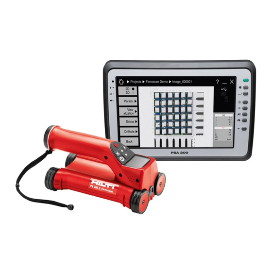
PS 200 S Ferroscan. The designation are read before the tool is operated for the “PS 250 Ferroscan system” applies to the whole system first time. consisting of the PS 200 S scanner, PSA 100 monitor and PROFIS Ferroscan PC software for data evaluation. -
Page 5: Description
The type designation and serial number can be found on the type identification plate on the tool. Make a note of this data in your operating instructions and always refer to it when making an enquiry to your Hilti representative or service department. Read the... -
Page 6: Items Supplied, Accessories, Spare Parts
Reports can also be printed. 3 Items supplied, accessories, spare parts 3.1 Items supplied 3.1.1 PS 250 Ferroscan system Num- Designation Comments... - Page 7 Set of 6 red and 6 black marking pens for marking the grid position and object position PROFIS Ferroscan software PC software on CD-ROM for the PS 250 Ferroscan system / PS 200 S Ferroscan set PSA/PUA operating instruc- tions...
- Page 8 Set of 6 red and 6 black marking pens for marking the grid position and object position PROFIS Ferroscan software PC software on CD-ROM for the PS 250 Ferroscan system / PS 200 S Ferroscan set PSA/PUA operating instruc- tions...
- Page 9 2006200 PSA 65 carrying device For the PSA 100 monitor 319416 Hilti PROFIS Ferroscan PC soft- PC software on CD-ROM for the PS 250 Ferroscan system / ware PS 200 S scanner set 2031824 Hilti toolbox for PS 250 2044483...
-
Page 10: Technical Data
Comments 2004815 PSA 100 P2 operating instruc- For USA / Canada tions 2037330 PS 200 S Ferroscan / PS 250 For Europe / Asia Ferroscan system P1 operating instructions 2037331 PS 200 S Ferroscan / PS 250 For USA / Canada... - Page 11 Item no. Standard Origin / applicability of the stand- 2044438, 2044470, 2044476, JIS G 3112 Japan, Korea 2044478, 377651 2044471, 2044479, 408056 GB 50010-2002 China 4.3 Detection range, measurement range and accuracy NOTE If one or more of the specified conditions are not fulfilled, accuracy and precision may be compromised. The ratio of bar spacing to depth of cover (s:c) is often a limiting factor in resolving individual bars.
- Page 12 4.3.1.2 Bar diameter as per ASTM Depth in mm Bar diameter ±5 ±2 ±2 ±3 ±4 ±5 ±2 ±2 ±3 ±4 ±10 ±5 ±2 ±2 ±3 ±4 ±10 ±12 ±5 ±2 ±2 ±3 ±4 ±10 ±12 ±2 ±2 ±3 ±4 ±5 ±10 ±12...
- Page 13 4.3.1.5 Bar diameter as per GB 50010-2002 Depth in mm Bar diameter in mm ±5 ±2 ±3 ±3 ±4 ±5 ±2 ±2 ±3 ±4 ±5 ±2 ±2 ±3 ±4 ±10 ±5 ±2 ±2 ±3 ±4 ±10 ±12 ±2 ±2 ±3 ±4 ±5 ±10...
- Page 14 Depth in mm Bar diameter ±3 ±3 ±4 ±6 ±8 ±12 ±14 ±3 ±3 ±4 ±6 ±8 ±12 ±14 ±3 ±3 ±4 ±6 ±8 ±12 ±14 ±3 ±3 ±4 ±6 ±8 ±12 ±14 ±16 The value indicates the typical accuracy of the depth measurement (deviation from actual) in mm. 0: Bar is visible at this depth but no depth is calculated.
- Page 15 Depth in mm Bar diameter in mm ±3 ±3 ±4 ±6 ±8 ±3 ±3 ±4 ±6 ±8 ±12 ±3 ±3 ±4 ±6 ±8 ±12 ±14 ±3 ±3 ±4 ±6 ±8 ±12 ±14 ±3 ±3 ±4 ±6 ±8 ±12 ±14 ±3 ±3 ±4 ±6...
- Page 16 Depth in mm Bar diameter ±5 ±1 ±1 ±2 ±2 ±4 ±1 ±1 ±2 ±2 ±4 ±5 ±1 ±1 ±2 ±2 ±4 ±6 The value indicates the typical accuracy of the depth measurement (deviation from actual) in 0: Bar is visible at this depth but no depth is calculated. X: Bar cannot be detected at this depth.
- Page 17 4.3.3.5 Bar diameter as per GB 50010-2002 Depth in mm Bar diameter in mm ±5 ±1 ±1 ±2 ±2 ±4 ±5 ±1 ±1 ±2 ±2 ±4 ±5 ±1 ±1 ±2 ±2 ±4 ±5 ±1 ±1 ±2 ±2 ±4 ±1 ±1 ±2 ±2 ±4...
- Page 18 Depth in mm Bar diameter ±5 ±2 ±2 ±2 ±3 ±4 ±2 ±2 ±2 ±3 ±4 ±5 ±2 ±2 ±2 ±3 ±4 ±5 ±2 ±2 ±2 ±3 ±4 ±5 ±2 ±2 ±2 ±3 ±4 ±5 ±2 ±2 ±2 ±3 ±4 ±5 The value indicates the typical accuracy of the depth measurement (deviation from actual) in 0: Bar is visible at this depth but no depth is calculated.
- Page 19 4.3.4.5 Bar diameter as per GB 50010-2002 Depth in mm Bar diameter in mm ±5 ±2 ±2 ±2 ±3 ±4 ±5 ±2 ±2 ±2 ±3 ±4 ±5 ±2 ±2 ±2 ±3 ±4 ±5 ±2 ±2 ±2 ±3 ±4 ±2 ±2 ±2 ±3 ±4...
-
Page 20: Safety Instructions
Make sure that the toolbox is properly secured during b) To avoid the risk of injury, use only genuine Hilti transport and does not present a risk of injury. accessories and additional equipment. -
Page 21: Before Use
Do not use the tool if it is defective. mental pollution. d) If you are unsure of the scan results, consult a Hilti e) Remove the battery pack before transporting the tool specialist before proceeding. -
Page 22: Operation
PS 250 Ferroscan sys- PSA 100 monitor. The monitor can be kept nearby (e.g. tem. Some of the components of the PS 250 Ferroscan at the foot of the scaffold, in a vehicle, in the site office system may suffer damage if exposed to temperatures etc.). - Page 23 settings menus are displayed as symbols on the left side of the screen. Use the Arrow buttons to toggle between these options. Press the Confirm button to confirm the selected option. Quickscan The remaining memory for Quickscan recording is shown at the top of the screen in meters or feet (depending on the scanner type and units set).
- Page 24 The Arrow buttons are used to select the options. The selected option can be confirmed / activated by pressing the Confirm button and the Cancel button then pressed to return to the main menu. 7.2.4.1 Set display backlight Select the backlight adjustment function by pressing the Confirm button. Use the Arrow buttons to toggle between the individual options.
- Page 25 7.2.4.2 Adjusting the volume Sets the volume level of the audible signal during scanning. Use the Arrow buttons to toggle between the various options. Press the Confirm button to select the desired option and press the Cancel button to return to the settings menu.
- Page 26 Press the Down arrow button followed by the Confirm button to delete data. Alternatively, press the Cancel button to return to the settings menu. 7.2.5 Quickscan CAUTION The scanner detects only reinforcing bars that lie at right angles to the direction of travel. Bars that lie parallel to the direction of travel will not be detected.
- Page 27 The bar is positioned along the center line of the scanner and may be marked on the surface using a PUA 70 marking pen. Depth measurement accuracy can be increased by entering the correct rebar diameter or by switching to accurate depth measurement measuring mode (see 7.2.5.2).
- Page 28 If the spacing distance is known, the value can also be entered manually using the Arrow buttons. After setting the bar diameter and the spacing distance, the procedure is exactly the same as for Quickscan detection ( see 7.2.5.1). 7.2.5.3 Quickscan recording WARNING Always make an Imagescan or use Quickscan detection in both directions prior to making a Quickscan recording in order to:...
- Page 29 A stretch of up to 30 m in length can be recorded before it is necessary to transfer the data to the PSA 100 monitor or the PSA 55 infrared adapter. It is also possible to record several separate stretches (max. 10) that add up to a maximum of 30 m.
- Page 30 Quickscan recordings are subsequently correctly displayed in Hilti PROFIS Ferroscan MAP (data evaluation and presentation application) and that the depth values correspond with the actual surface of the structure. This makes it easier to subsequently locate the positions of areas with inadequate cover. The scan direction is saved with each Quickscan recording.
- Page 31 are located within a scan, providing additional information that creates a reference between the scan data and the actual surface. To set a marker, press and hold the Confirm button while in recording mode. The diskette symbol will be crossed out, indicating that recording has been suspended and a marker has been set.
- Page 32 A representation of the grid appears on the screen with a suggested starting point (triangle). This is always at upper left and will be suitable for most scans. Image data will be generated only for areas of the grid that have been scanned both vertically and horizontally.
- Page 33 The scanner emits a double beep at the end of the row and automatically stops recording. This procedure should be repeated for each row and column while observing the instructions shown in the display. When all rows have been completed, the columns should also be scanned in the same way. The scanning operation for any row or column may be interrupted before reaching the end by pressing Record again.
- Page 34 Attach the reference grid in the same way as for an Imagescan. Use a PUA 70 marking pen to mark the edges or the punched holes at the end of each reference grid for the transition to the next grid, as shown below. Any additional reference grids required should be attached to the wall so that their edges correspond and are in alignment with each other.
- Page 35 PROFIS Ferroscan (V 5.7) software. If this is not the NOTE case, the device driver must be installed manually by Install the Hilti PROFIS Ferroscan 5.7 software (or a higher running the “setup.exe” file located in the “Drivers” folder version) on your PC/laptop. The date and time must be on the PSA 55 IR adapter.
- Page 36 The green LED lights constantly: The adapter is This screen appears on the scanner while data transfer switched on and is ready for operation. is in progress and the red LED on the scanner blinks The red LED blinks rapidly: Battery charge state is continuously.
- Page 37 In such cases it is also advantageous to functions, use only the PUA 95 Micro USB cable supplied scan through a thin overlay board. Also in this case, the by Hilti. thickness of the board must be deducted from any depth measurements.
-
Page 38: Care And Maintenance
8.5 Hilti Calibration Service Observe the temperature limits when storing your equip- We recommend that the tool is checked by the Hilti Cal- ment, especially in winter / summer if the equipment is ibration Service at regular intervals in order to verify its kept inside a motor vehicle (-25°C to +60°C). -
Page 39: Troubleshooting
Badly scratched windows must be replaced by Hilti Ser- vice. Try to hold the monitor and scanner steady and in correct alignment with each other until data... - Page 40 If the error message re- A stop symbol generally switched on. appears the tool must be indicates a fatal error in returned to Hilti for repair. the scanner. A stop symbol generally indicates a fatal error in the scanner. This symbol may appear...
-
Page 41: Disposal
Most of the materials from which Hilti tools or appliances are manufactured can be recycled. The materials must be correctly separated before they can be recycled. In many countries, Hilti has already made arrangements for taking back old tools or appliances for recycling. -
Page 42: Ec Declaration Of Conformity (Original)
Additional claims are excluded, unless stringent na- For repair or replacement, send the tool or related parts tional rules prohibit such exclusion. In particular, Hilti immediately upon discovery of the defect to the address is not obligated for direct, indirect, incidental or con- of the local Hilti marketing organization provided. - Page 43 Tel.: +423 / 234 21 11 Fax: +423 / 234 29 65 www.hilti.com Hilti = registered trademark of Hilti Corp., Schaan W 4215 | 0113 | 00-Pos. 1 | 1 Printed in Germany © 2013 Right of technical and programme changes reserved S. E. & O.