Table of Contents
Advertisement
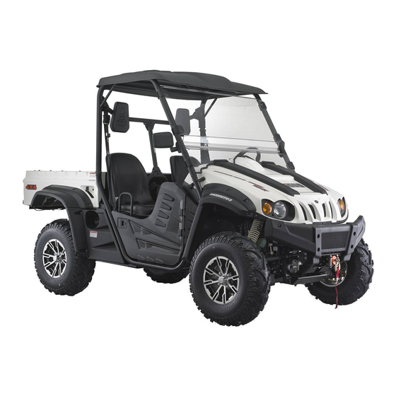
HS500
OWNER' S
MANUAL
No one under the age of 16 should operate this vehicle.
Provincial / Municipal governments have different
regulations pertaining to owning and operating an
off-road vehicle; learn the regulations in your area.
READ THIS MANUAL CAREFULLY
For questions regarding this UTV,
please contact HISUN at:
(877) 838-6188
www.hisunmotors.com
REV. 01231401
Advertisement
Table of Contents

Related Manuals for Hisun HS500


Summary of Contents for Hisun HS500
- Page 1 No one under the age of 16 should operate this vehicle. Provincial / Municipal governments have different regulations pertaining to owning and operating an off-road vehicle; learn the regulations in your area. READ THIS MANUAL CAREFULLY For questions regarding this UTV, please contact HISUN at: (877) 838-6188 www.hisunmotors.com REV. 01231401...
- Page 2 Owner’s Manual...
- Page 3 Owner Manual INTRODUCTION Congratulations on your purchase of the HS500UTV-4/HS500UTV-3. This Owner’s / Operator’s manual will provide you information regarding safe operation, operational instructions, maintenance and care. Fully understanding this manual and following all of the instructions herein will provide the knowledge needed to have safe and enjoyable UTV operation.
-
Page 4: Important Manual Information
Owner’s Manual IMPORTANT MANUAL INFORMATION FAILURE TO FOLLOW THE WARNINGS CONTAINED IN THIS MANUAL CAN RESULT IN SERIOUS INJURY Particularly important information is distinguished in this manual by the following OR DEATH. notations: The Safety Alert Symbol means ATTENTION! YOUR SAFETY IS INVOLVED! Failure to follow WARNING instructions could result in severe injury or death to the machine operator, bystander or a person inspecting or repairing the machine. -
Page 5: Important Notice
Owner Manual IMPORTANT NOTICE This UTV is designed and manufactured for OFF - ROAD use only. It is illegal and unsafe to operate this UTV on any public street, road or highway. This UTV complies with all applicable OFF - ROAD noise level and spark arrester laws and regulations in effect at the time of manufacture. -
Page 6: Table Of Contents
Owner’s Manual Fuel level indicator Location of the Warning and Switches Specification Labels On-Command Four-Wheel-Drive and Differential Gear Lock Switches 4-10 Safety Information Accelerator Pedal 4-14 Brake Pedal 4-15 Description and Vehicle Parking Brake Lever 4-15 Identification Identification Number Records Drive Select Lever 4-16 Vehicle Identification Number... - Page 7 Owner Manual Auxiliary DC Jack 4-31 Fittings and Fasteners 5-10 Lights 5-10 Switches 5-11 Pre Operation Checks Tires 5-11 Brakes How to Measure Tire Pressure 5-12 Brake Fluid Level Tire Wear Limit 5-13 Brake Fluid Leakage Brake Operation Operation Starting the Engine in Low Fuel Temperatures Gasohol...
- Page 8 Owner’s Manual Hood Driving Your Vehicle Console Getting to Know Your Vehicle EFI System Learning to Operate Your Vehicle 8-12 Turning your Vehicle EFI System inspection 8-12 Operating Improperly in Reverse Engine oil and oil filter cartridge 8-12 Braking To Check the Engine Oil Level 8-13 Going Uphill To Change the Engine Oil...
- Page 9 Owner Manual V-belt Cooling Duct Check Hose 8-30 Battery 8-43 V-belt Case Drain Plug 8-30 Battery Maintenance 8-45 Cleaning the Spark Arrester 8-31 Fuse Replacement 8-45 Valve Clearance 8-33 Replacing A Headlight Bulb 8-47 Front Brake Pad Check 8-33 Headlight Beam Adjustment 8-50 Rear Brake Pad Check 8-34...
- Page 10 Owner’s Manual EPS system’s inspection, 12-1 Fault code of Electronic Injection 9-15 maintenance, repair System To drive UTV at every time, need to do daily inspection of EPS system USA EPA Emissions Limited 13-1 Malfunction assortment 9-15 Warranty Solutions for common fault 9-19 Maintenance and repair’s supplemental description...
- Page 11 Location of the Warning and Safety Labels ⑭ ⑬...
- Page 12 Location of the Warning and Safety Labels Read and understand all of the labels on your vehicle. They contain important information for safe and proper operation of your vehicle. Never remove any labels from your vehicle. If a label becomes difficult to read or comes off, a replacement label is available by contacting your dealer.
- Page 13 Location of the Warning and Safety Labels...
- Page 14 Location of the Warning and Safety Labels...
- Page 15 Location of the Warning and Safety Labels...
- Page 16 Location of the Warning and Safety Labels...
- Page 17 Location of the Warning and Safety Labels...
-
Page 18: Safety Information
Safety Information SAFETY INFORMATION This off-highway utility vehicle handles differently from other vehicles including cars and UTVs. SEVERE INJURY OR DEATH can result if you do not follow these instructions: Read this manual and all labels carefully and follow the operating procedures described. ●... - Page 19 Safety Information Never attempt jumps or other stunts. ● Always inspect your vehicle each time you use it to be sure it is in safe operating condition, Always ● follow the inspection and maintenance procedures and schedules described in this manual. Always keep hands, arms, feet, and legs inside the vehicle at all times during operation.
- Page 20 Safety Information Never operate on hills that are slippery or ones where you will not be able to see far enough ahead of ● you. Never go over the top of a hill at speed if you cannot see what is on other side. Always follow proper procedures for going uphill.
- Page 21 Safety Information WARNING POTENTIAL HAZARD Improper handling of gasoline. WHAT CAN HAPPEN Gasoline can catch fire and you could be burned. HOW TO AVOID THE HAZARD Always turn off the engine when refueling. Do not refuel right after the engine has been running and is still very hot.
- Page 22 Safety Information WARNING POTENTIAL HAZARD Starting or running the engine in a closed area. WHAT CAN HAPPEN Exhaust fumes are poisonous and may cause loss of consciousness and death within a short time. HOW TO AVOID THE HAZARD Always operate your vehicle in an area with adequate ventilation.
-
Page 23: Description And Vehicle Identification
Description and Vehicle Identification Headlights Spark arrester Front shock absorber assembly adjusting ring Passenger seat belt Brake fluid reservoir Passenger seat Air filter element(engine and air intake duct) Oil filter cartridge V-belt case Engine oil dipstick Driver seat Battery Driver seat belt Fuses Spark plug Coolant reservoir... - Page 24 Description and Vehicle Identification Light switch Steering wheel Starter Main switch On-Command four-wheel-drive and differential lock switches Multi-function meter unit Auxiliary DC jack Drive select lever Parking brake lever Accelerator pedal Brake pedal NOTE: The vehicle you have purchased may differ slightly from those in the figures of this manual.
-
Page 25: Identification Number Records
Description and Vehicle Identification Identification Number Records Record the Vehicle Identification Number and Vehicle Identification Number model label information in spaces provided for The Vehicle Identification Number (VIN) is assistance when ordering spare parts from a stamped into the frame. service center or for reference in case the vehicle is stolen. -
Page 26: Control Functions
Control Functions Functions of the respective switch positions CONTROL FUNCTIONS are as follows: All electrical circuits are supplied with power, Main switch and the headlights and taillights illuminate when the light switch is on. OFF: All electrical circuits are switched off. The key can be removed in this position. -
Page 27: Indicator And Warning Lights
Control Functions Indicator and Warning Lights CAUTION: Do not operate the electric starter ● continuously for more than 5 seconds at a time or starter damage could occur. Wait at least 5 seconds between each start attempt. Do not turn the key to the “START” ●... - Page 28 Control Functions This indicator light comes on when the drive Low-Range Indicator Light “L” select lever is in the “R” reverse position. This indicator light comes on when the drive select lever is in the “L” position. Coolant Temperature Warning Light “ ”...
-
Page 29: Use Of Eps System
Control Functions is out. Continuous use while the light is monitors working condition of EPS system. on may cause damage to the engine. Fault can be displayed by fault indicator light High beam indicator and fault indicator of EPS system, so the The light being on means headlight is at high driver can acknowledge fault of EPS in time beam mode. - Page 30 Control Functions Speedometer Unit Check the meter. If fault indicator light of EPS system does not be lit, ECU can be for regular use. If fault indicator light of EPS system is lit, that means EPS system find out some fault during ECU self-checking process, then you should consult your local dealer for maintenance in time.
-
Page 31: Speedometer Unit
Control Functions Speedometer unit functions: from the odometer, to the tripometer, and a speedometer (which shows the speed) then to the hours meter; then it starts the an odometer (which shows the total cycle over. distance covered) The odometer displays the total distance a tripometer (which can be cleared and traveled by the UTV. -
Page 32: Clock Time Adjustment
Control Functions button on the display. This will also change circle on the front axle when the grey and displayed mileage from miles yellow 4WD selector buttons are pressed in kilometers. indicating the “4WD” function has been Clock time adjustment activated. -
Page 33: Fault Code Indicator
Control Functions When riding on a flat road at a comparatively CAUTION: high speed, adjust settings If the display indicators flash or the “2WD/UNLOCK” and there are no symbols speedometer does not show the speed while in either of the 4WD indicators. the UTV is in motion, Ask a dealer to check Riding an UTV while the differential the speed sensor and circuits. -
Page 34: Fuel Level Indicator
Control Functions fixed, will the time show automatically. Switches The description for the fault codes are shown in Chapter 11 of this manual. Fuel level indicator The fuel level display will indicate the fuel volume. When the fuel is getting low the fuel pump symbol will flash. -
Page 35: On-Command Four-Wheel-Drive And Differential Gear Lock Switches
4-10 Control Functions On-Command Four-Wheel–Drive and CAUTION: Differential Gear Lock Switches Do not use the headlights with the engine turned off for an extended period of time. The battery may discharge to the point that the starter motor will not operate properly. If this happens, remove the battery and recharge it. - Page 36 Control Functions 4-11 conditions. Two-wheel drive (”2WD”): Power is sup- WARNING plied to the rear wheels only. POTENTIAL HAZARD Changing from 2WD to 4WD or from 2WD Four-wheel drive (“4WD’): Power is to 2WD-Differential UNLOCK, or supplied to the rear and front wheels. vice-versa while the vehicle is moving.
- Page 37 4-12 Control Functions the select lever is set to positionⓐ, and On-Command four-wheel-drive switch then set the switch to “2WD”. “2WD/4WD” On-Command Differential Gear Lock Switch “4WD”/”LOCK” Select lever On-Command four –wheel-drive switch “2WD/4WD” To change from 2WD to 4WD ,stop the vehicle, and then set the switch to On-Command differential gear lock switch “4WD”/ “LOCK”...
- Page 38 Control Functions 4-13 set the switch to “LOCK”. When the differential gear is locked, the differential HOW TO AVOID THE HAZARD gear lock indicator light will come on along Always ride at a slow speed when the with the differential gear lock indicatorin the vehicle is in 4WD-LOCK, and allow extra multifunction meter unit display .To release time and distance for maneuvers.
-
Page 39: Accelerator Pedal
4-14 Control Functions will cause the engine speed to be limited until engagement is complete. Accelerator pedal Press the accelerator pedal down to increase engine speed. Spring pressure returns the pedal to the rest position when released. Always check that the accelerator pedal returns normally before staring the engine. -
Page 40: Brake Pedal
Control Functions 4-15 Brake pedal Press the brake pedal to slow or stop the vehicle. WARNING POTENTIAL HAZARD Malfunction of the accelerator pedal. WHAT CAN HAPPEN A faulty pedal that makes it difficult to speed up or slow down could cause loss of control. -
Page 41: Drive Select Lever
4-16 Control Functions lever, press the release button, and then Drive select lever push the lever all the way down. Spring The drive select lever is used to shift you pressure helps return the lever to the vehicle into the low, high, neutral and reverse released position. -
Page 42: Fuel Tank Cap
Control Functions 4-17 Fuel tank cap Seats Remove the fuel tank cap by turning it To remove a seat, pull its seat lock lever counterclockwise. upward, lift the front of the seat, and then slide the seat forward and up. 1. -
Page 43: Seat Belts
4-18 Control Functions To install a seat, insert the projection on the rear of the seat into the seat holders and push down on the seat at the front. WARNING POTENTIAL HAZARD A loose seat. WHAT CAN HAPPEN The operator could lose control or the operator or passenger could fall if the seat is loose during operation. - Page 44 Control Functions 4-19 2. Push the latch plate into the buckle until it clicks. Pull up on the latch plate to make sure it is secure. 1. Seat belt (×2) 2. Latch plate (×2) 3. Buckle (×2) To wear the seat belt properly, do the 1.
- Page 45 4-20 Control Functions shoulder belt should fit against your chest. If it is loose, pull the belt out all the WARNING way and then let it retract. POTENTIAL HAZARD 5. To release the buckle, firmly press the Not wearing the seat belt or wearing the release button.
-
Page 46: Glove Compartment
Control Functions 4-21 Glove compartment Cargo bed CAUTION: To protect from damage, do not put metal products, like tools or sharply edged products directly in the glove compartment. If they must be stored, wrap them in appropriate cushion material. 1. Cargo bed 2. -
Page 47: Opening And Closing The Tailgate
4-22 Control Functions Opening and closing the tailgate Lifting and lowering the cargo bed 1. Tailgate 2. Latch (×2) 1. Cargo bed release lever To lift To open Push down cargo bed release lever on left or Unhook the latches, and then lower the right side of the vehicle;... - Page 48 Control Functions 4-23 WARNING WARNING POTENTIAL HAZARD POTENTIAL HAZARD Overloading the cargo bed Pinch points. WHAT CAN HAPPEN WHAT CAN HAPPEN Could cause changes in vehicle handling You or someone else could be pinched which could lead to an accident. between the cargo bed and the frame HOW TO AVOID THE HAZARD when the bed is being lowered.
-
Page 49: Front And Rear Shock Adjustment
4-24 Control Functions Front and Rear Shock Adjustment(Option 1) WARNING The spring preload can be adjusted to suit the operating conditions. POTENTIAL HAZARD You can reduce preload for a softer ride, or Carrying a passenger in the cargo bed increase preload if frequent bottoming out of WHAT CAN HAPPEN the UTV occurs. - Page 50 Control Functions 4-25 Standard position: B A-Minimum(soft) E-Maximum(hard) 1. Spring preload adjusting ring 2. Position indicator NOTE: A special wrench can be obtained at a service center to make this adjustment. 1. Special wrench...
- Page 51 4-26 Control Functions Front and Rear Shock Adjustment(Option 2) WARNING WARNING POTENTIAL HAZARD These shock absorber assemblies Improper shock absorber adjustment. contain highly pressurized nitrogen gas, WHAT CAN HAPPEN read understand following Uneven adjustment can cause poor information before handling the shock handling and loss of stability, which absorber assemblies.
-
Page 52: Spring Preload
Control Functions 4-27 Spring preload 1. Loosen the locknut. ·Do not dispose of a damaged or worn 2. Turn the spring preload adjusting nut in out shock absorber assembly yourself. direction ⓐ to increase the spring Take the shock absorber assembly to a preload thereby harden... -
Page 53: Rebound Damping Force
4-28 Control Functions · A special wrench can be obtained at a Spring travel setting(Front) HSUN dealer to make this adjustment. Minimum(soft): 412mm(16.22 in) · The spring preload setting is determined Maximum(hard): 426mm(16.77 in) by measuring distance A, shown in the illustration. -
Page 54: Compression Damping Force
Control Functions 4-29 damping, and in direction F to decrease the Compression damping force rebound damping force and thereby soften Turn compression damping force the damping. adjusting screw (use 3.0 allen wrench) in direction ⓐ to increase the compression damping force and thereby harden the damping, and in direction ⓑ... -
Page 55: Trailer Hitch Bracket
4-30 Control Functions Trailer hitch bracket WARNING This vehicle is equipped with a 1 ¼ in receiver bracket for a standard trailer hitch. ·Suspension components become hot Trailer towing equipment can be obtained at during operation. Never touch a service center. (See pages 6-12 - 6-14 for compression damping force adjusting precaution information.) screw,... -
Page 56: Auxiliary Dc Jack
Control Functions 4-31 jack. Auxiliary DC jack The auxiliary DC jack is located at the right side of the front panel. The auxiliary DC jack can be used for suitable work lights, radios, etc. The auxiliary DC jack should only be used when the engine is running. - Page 57 4-32 Control Functions 4. When the auxiliary DC jack is not being used, cover it with the cap. CAUTION: Do not use accessories requiring more than the above maximum capacity. This may overload the circuit and cause the fuse to blow. If accessories are used without the engine running or with the headlights turned on, the battery will lose its charge...
-
Page 58: Pre Operation Checks
Pre Operation Checks Before using this vehicle, check the following items: ITEM ROUTINE PAGE Check operation, free play, fluid level and fluid leakage ● Brakes 5-2 - 5-3, 8-35 Fill with DOT 4 brake fluid if necessary ● Check for proper operation, condition and free play Parking brake ●... -
Page 59: Brakes
Pre Operation Checks WARNING Brakes Check for correct brake pedal free play. If the POTENTIAL HAZARD brake pedal free play is incorrect, have a Failure to inspect the vehicle before service center adjust it. (See pages 8-38 - operating. Failure to properly maintain the 8-40.) vehicle. -
Page 60: Brake Fluid Leakage
Pre Operation Checks Brake fluid leakage Check to see if any brake fluid is leaking out of WARNING the pipe joints or the brake fluid reservoir. Apply POTENTIAL HAZARD the brakes firmly for one minute. If there is any Driving with improperly operating brakes. leakage, have the vehicle inspected by a WHAT CAN HAPPEN service center. -
Page 61: Fuel
Pre Operation Checks Fuel Your engine has been designed to use regular Make sure there is sufficient gasoline in the unleaded gasoline with a pump octane number tank. ([R+M] /2) of 91 or higher, or research octane number of 91 or higher. If knocking or pinging Recommended fuel: occurs, use a different brand of gasoline or Unleaded gasoline only... -
Page 62: Engine Oil
Pre Operation Checks Engine oil Make sure the engine oil is at the specified level. WARNING Add oil as necessary. (See pages 8-12-8-13) POTENTIAL HAZARD Improper care when refueling. CAUTION: WHAT CAN HAPPEN In order to prevent clutch slippage Fuel can spill, which can cause a fire and (since the engine oil also lubricates the severe injury. -
Page 63: Coolant
Pre Operation Checks CAUTION: Recommended engine oil type and Hard water or salt water is harmful to the engine. quantity: You may use soft water if you cannot get See page 10-2 distilled water. Coolant Coolant reservoir capacity Check the coolant level in the coolant reservoir (up to the maximum level mark): when the engine is cold. -
Page 64: Final Gear Oil
Pre Operation Checks Final gear oil Make sure the final gear oil is at the specified WARNING level. Add oil as necessary. (See pages 8-17 - POTENTIAL HAZARD 8-18 for details) Removing the radiator cap when the engine and radiator are still hot. Recommended oil: WHAT CAN HAPPEN SAE 80 API GL-4 Hypoid gear oil... -
Page 65: Throttle Pedal
Pre Operation Checks WARNING Recommended oil: Failure to check or maintain proper SAE 80 API GL-5 Hypoid gear oil operation of the throttle system can result in an accident and lead to serious injury or Throttle Pedal death if the throttle pedal sticks during Check to see that the accelerator pedal operation. -
Page 66: Throttle Freeplay
Pre Operation Checks Throttle Freeplay Throttle Freeplay Adjustment 1. Remove both seats. Remove the middle If the throttle pedal has excessive play due to cover of the engine. cable stretch or mis-adjustment, it will cause a 2. Loosen the nut of throttle cable on the delay in throttle response, especially at low valve, engine speed. -
Page 67: Steering Wheel Inspection
5-10 Pre Operation Checks 4. Resume the center cover and seat to their when pulled out and retract on its own when position released. The latch plate should click securely into the buckle and release when the release Steering Wheel Inspection button is pushed firmly. -
Page 68: Switches
Pre Operation Checks 5-11 as necessary for proper operation. Tires WARNING POTENTIAL HAZARD Switches Operating this vehicle with improper tires, Check the operation of all switches. Have a or with improper or uneven tire pressure. service center repair as necessary for proper WHAT CAN HAPPEN operation. -
Page 69: How To Measure Tire Pressure
5-12 Pre Operation Checks 3. The tires should be set to the 5. Use no more than the following pressures recommended pressure: when seating the tire beads. Front 10psi (70kpa, 0.7 kgf/cm Front 36psi (250kpa, 2.5kgf/cm Rear 10psi (70kpa, 0.7 kgf/cm Rear 36psi (250kpa, 2.5kgf/cm Check and adjust tire pressures when the Higher pressures may cause the tire to burst. -
Page 70: Specifications
Pre Operation Checks 5-13 Set pressure with tires cold. Set tire pressures Tire wear limit to the following specifications: When the tire groove decreases to 0.12 in (3 Recommended mm) due to wear, replace the tire. Minimum Maximum Pressure 10psi (70kpa 9 psi (63kpa, 11 psi, (77kpa, Front... -
Page 71: Operation
Operation WARNING WARNING POTENTIAL HAZARD POTENTIAL HAZARD Operating vehicle without being familiar Freezing control cables due to cold with all controls. weather conditions. WHAT CAN HAPPEN WHAT CAN HAPPEN Loss of control, which could cause an Loss of vehicle control, which could accident or injury. -
Page 72: Starting The Engine
Operation service center to inspect the electric Starting the Engine circuit. The engine can be started in any gear if CAUTION: ● the brake is applied. However, it is See the “Engine Break-In”section prior to operating the engine for the first time. recommended to shift into neutral ”N”... -
Page 73: Warming Up
Operation Continue warming up the engine until it idles smoothly before riding. 2500RPM to charge the battery for 5-10 minutes; when the voltage of battery is over 12V, the idle speed will be normal. If the WARNING idle speed is still high, please contact your POTENTIAL HAZARD service center. -
Page 74: Drive Select Lever Operation And Driving In Reverse
Operation Otherwise, go on with the third step. 1. Stop the vehicle. Keep your foot off the 3. Continue warming up the engine until it accelerator pedal. idles smoothly. 2. Apply the brakes, and then shift by CAUTION: moving the drive select lever along the See the “Engine break-in”... - Page 75 Operation the shift guide. NOTE: Please kick the brake pedal first, before place ● gearshifts lever to“reverse”position. In the brake pedal, there is a cable, which is ● connected to a position pin located on the gearshift assembly. Only when the brake pedal is depressed, the position pin will be retracked, and gearshifts can be removed to “reverse”...
- Page 76 Operation until the vehicle starts moving. 4. Check behind for people or obstacles, and then release the brake pedal. 5. Press the accelerator pedal gradually and continue to watch to the rear while backing up. 1. Drive select lever NOTE: When in reverse, the reverse indicator ●...
- Page 77 Operation WARNING WARNING POTENTIAL HAZARD POTENTIAL HAZARD Parking on a hill or other incline. Improperly operating in reverse. WHAT CAN HAPPEN WHAT CAN HAPPEN The vehicle could roll out of control, You could hit an obstacle or person increasing the chance of an accident. behind you, resulting in serious injury.
-
Page 78: Parking
Operation Parking Parking on a Slope a) When parking, stop the engine and shift the drive select lever into the neutral position. b) Push the brake pedal down, and pull the parking brake to top position to park the vehicle 1. -
Page 79: Vehicle Break-In Period
Operation Vehicle Break-in Period The break-in period for your new UTV vehicle is the first 25 hours of operation, or the time it takes to use the first three tanks full of gasoline. No single action on your part is as important as a proper break-in period. Careful treatment of a new engine and drive components will result in more efficient performance and longer life for these... -
Page 80: Engine Break-In
Operation 6-10 momentary (2-3 seconds maximum) full of use. Use of any engine oil not mentioned in throttle operation under load does not harm ● this manual will cause severe damage to the engine. the engine. Each full throttle acceleration sequence should be followed with a substantial rest period for the engine by cruising at lower Engine Break-In... -
Page 81: Accessories
6-11 Operation 10-25 Hours: performance. Break in the clutches and belt Avoid prolonged operation above 3/4 throttle. by operating at slower speeds during the Rev the vehicle freely but do not use full break-in period as recommended. Pull only throttle at any time. light loads. -
Page 82: Loading
Operation 6-12 test all nonstandard accessories, nor with accessories. The vehicle may have any control over the quality or handle differently than it does without suitability of them. Choose a genuine accessories. accessory, or one that is equivalent in design and quality. Loading Accessories should be rigidly and Cargo or a trailer can change the stability... - Page 83 6-13 Operation the loaded trailer on the scale with the tongue at hitch height. Adjust the load in MAXIMUM LOADING LIMIT the trailer, if necessary, to reduce the Vehicle loading limit (total weight of ● cargo, operator, passenger and weight on hitch. If you are carrying cargo accessories, and tongue weight): and towing a trailer, include the tongue 882 lb (400Kg)
- Page 84 Operation 6-14 Make sure cargo in the trailer cannot Avoid hills and rough terrain. Choose ● move around. A shifting load can cause terrain carefully. Added weight affects the an accident. stability and handling of the vehicle. Make sure the load does not interfere ●...
- Page 85 6-15 Operation WARNING POTENTIAL HAZARD Overloading this vehicle or carrying or towing cargo improperly. WHAT CAN HAPPEN Could cause changes in vehicle handling which could lead to an accident. HOW TO AVOID THE HAZARD Never exceed the stated load capacity for this vehicle.
-
Page 86: Driving Your Vehicle
Your Vehicle DRIVING YOUR VEHICLE WARNING GETTING TO KNOW YOUR VEHICLE POTENTIAL HAZARD This off-highway utility vehicle will handle Not wearing the seat belt. and maneuver differently form an ordinary Wearing the seat belt improperly. passenger car or other vehicle. WHAT CAN HAPPEN Before you begin to use your vehicle, be sure There is increased risk of being killed or... - Page 87 Your Vehicle WARNING The total weight of operator, passenger, accessories, cargo, trailer tongue weight, POTENTIAL HAZARD and the vehicle itself must not exceed 1,880 Carrying a passenger in the cargo bed. lbs (853Kg). WHAT CAN HAPPEN The passenger could fall or be struck by objects in the cargo bed.
- Page 88 Your Vehicle The driver and passenger must always wear WARNING a seat belt, an approved motorcycle helmet, POTENTIAL HAZARD eye protection and protective clothing, Overloading this vehicle or carrying or including over-the-ankle boots, gloves, a towing cargo improperly. long-sleeved shirt or jacket, and long pants. WHAT CAN HAPPEN Keep hands and feet inside the vehicle at all Could cause changes in vehicle...
- Page 89 Your Vehicle WARNING HOW TO AVOID THE HAZARD POTENTIAL HAZARD Always wear an approved motorcycle Operating this vehicle without wearing an helmet that fits properly. You should also approved motorcycle helmet, eye wear: protection, and protective clothing. WHAT CAN eye protection HAPPEN (goggles or face shield) Operating without...
-
Page 90: Learning To Operate Your Vehicle
Your Vehicle Perform the Pre-Operation Checks on pages LEARNING TO OPERATE YOUR VEHICLE 5-1 - 5-11. Set the parking brake, shift to You should become familiar with the neutral, and follow the instructions on page performance characteristics of the vehicle in 6-1 to start the engine. -
Page 91: Turning Your Vehicle
Your Vehicle maneuvers on slope. Position your hands on the steering wheel so CAUTION: that your thumbs and fingers do not wrap Do not shift from low to high or vice versa around the wheel. This is particularly important without coming to a complete stop and when driving in rough terrain. -
Page 92: Operating Improperly In Reverse
Your Vehicle Follow these precautions when operating in reverse: 1. Always check for obstacles or people behind the vehicle. 2. Apply the throttle lightly. Never open the throttle suddenly. 3. Back up slowly. 4. Apply the brakes lightly for stopping. 5. -
Page 93: Braking
Your Vehicle BRAKING Braking ability is affected by the type of terrain. In most cases, gradual application of the brakes is more effective than abrupt braking, particularly on loose surfaces like gravel. Always allow for greater braking distance on rough, loose, or slippery surfaces. - Page 94 Your Vehicle some hills are too steep for you to climb. WARNING Maximum slope angle:15° POTENTIAL HAZARD Operating on excessively steep hills. WHAT CAN HAPPEN The vehicle can over turn more easily on extremely steep hills than on level surfaces or small hills. HOW TO AVOID THE HAZARD Never operate your vehicle on hills too steep for it or your abilities.
-
Page 95: Going Downhill
7-10 Your Vehicle Before climbing the hill, first be sure you are around. With your foot on the brake, look operating in low range 4WD or, if necessary, behind you and plan your descent. Shift the with 4WD. To climb a hill, you need traction, drive select lever in reverse so you can use momentum, and steady throttle. - Page 96 Your Vehicle 7-11 Before starting downhill, make sure the you will be able to react to obstacles that may vehicle is in low-range 4WD. On most slopes, appear. this will let you use engine braking to help you go downhill slowly. Go as slowly as WARNING possible.
-
Page 97: Crossing Through Shallow Water
7-12 Your Vehicle CROSSING THROUGH SHALLOW WATER WARNING If you must cross shallow, slow moving water POTENTIAL HAZARD up to the depth of the vehicle’s floorboards, Operating this vehicle through deep or choose your path carefully to avoid sharp fast-flowing water. drop-offs, large rocks, or slippery surfaces WHAT CAN HAPPEN Loss of control, which could result in an... -
Page 98: Vehicle Immersion
Your Vehicle 7-13 Vehicle Immersion CAUTION: CAUTION: After riding your vehicle in water, be sure to If your vehicle becomes immersed, major drain the trapped water by removing the engine damage can result if the machine is check hose at the bottom of the air filter case, not thoroughly inspected. - Page 99 7-14 Your Vehicle 5. Dry the spark plugs and reinstall them, or install new plugs. CAUTION: 6. Attempt to start the engine. If necessary, Make sure all components that are washed repeat the drying procedure. and assembled are coated lightly with 7.
-
Page 100: Riding Over Rough Terrain
Your Vehicle 7-15 1. Drive select lever box check hose 1.V-belt cooling duct check hose 1.V-belt case drain plug Riding Over Rough Terrain Operating over rough terrain should be done with caution. Look for obstacles that could cause damage to the vehicle or could lead to a rollover accident. - Page 101 7-16 Your Vehicle vehicle could occur. WARNING POTENTIAL HAZARD Failure to use extra care when operating this vehicle on unfamiliar terrain. WHAT CAN HAPPEN You can come upon hidden rocks, bumps, or holes, without enough time to react. Could result in the vehicle overturning or going out of control.
-
Page 102: Riding In Brush Or Wooded Areas
Your Vehicle 7-17 thoroughly. Look from both your approach Riding in Brush or Wooded Areas side and the exit side. If you believe you can When operating in areas with brush or trees, continue safely, decide the path that will watch carefully on both sides and above the allow you to get over the obstacle at as close vehicle for obstacles such as branches that... - Page 103 7-18 Your Vehicle WARNING POTENTIAL HAZARD Improperly operating over obstacles. WHAT CAN HAPPEN Could cause loss of control or a collision. Could cause the vehicle to overturn. HOW TO AVOID THE HAZARD Before operating in a new area, check for obstacles.
-
Page 104: Periodic Maintenance And Adjustment
Periodic Maintenance and Adjustment NOTE: Periodic Maintenance and Adjustment If you do not have a torque wrench available Periodic inspection, adjustment and during a service operation requiring lubrication will keep your vehicle in the safest one, take your vehicle to service center to and most efficient condition possible. - Page 105 Periodic Maintenance and Adjustment WARNING WARNING POTENTIAL HAZARD POTENTIAL HAZARD Operating this vehicle with improper Servicing an engine while it is running. modifications. WHAT CAN HAPPEN Moving parts can catch clothing or parts WHAT CAN HAPPEN of the body, causing injury. Improper installation of accessories or Electrical components can cause shocks modification of this vehicle may cause...
-
Page 106: Periodic Maintenance Chart For The Emission Control System
Periodic Maintenance and Adjustment Periodic Maintenance Chart for the Emission Control System ● For vehicles not equipped with an odometer or hour meter, follow the month maintenance intervals. ● For vehicles equipped with an odometer or an hour meter, follow the mile (km) or hours maintenance intervals. However, keep in mind that if the vehicle is not used for a long period, the month maintenance intervals should be followed. -
Page 107: General Maintenance And Lubrication Chart
Periodic Maintenance and Adjustment General maintenance and lubrication chart INITIAL EVERY Month Whichever ITEM ROUTINE Miles 1,500 1,500 3,000 Comes first (Km) (320) (2,400) (2,400) (4,800) (1,200) hours Check coolant leakage. ● Cooling system Repair if necessary. ○ ○ ○ ○... - Page 108 Periodic Maintenance and Adjustment INITIAL EVERY Month Whichever ITEM ROUTINE Miles 1,500 1,500 3,000 Comes first (Km) (320) (2,400) (2,400) (4,800) (1,200) hours Check bearing assemblies for looseness/damaged. ● Wheel bearings* ○ ○ ○ ○ Repair if damaged. ● Stabilizer bushings* Check for cracks or damage.
- Page 109 Periodic Maintenance and Adjustment NOTE: Recommended brake fluld:DOT4 ● Brake fluid replacement. ● When disassembling the master cylinder or caliper, replace the brake fluid. Check the brake fluid level ● and add fluid as required. On the inner parts of the master cylinder and caliper, replace the oil seals every two years. ●...
-
Page 110: Hood
Periodic Maintenance and Adjustment Hood To open Unhook the hood latches, and then slowly tilt the hood up until it stops. Hood To close Lower the hood slowly to its original position, 1. Latch (×2) and then hook the hood latches. Secure projections on the underside of the ①... -
Page 111: Console
Periodic Maintenance and Adjustment Console To remove 1. Remove the seats. (See pages 4-17─ 4-18 for seat removal and installation procedures.) 2. Remove the parking brake lever boot. 3. Pull the console upward (the drive select lever boot will come loose.) 1. -
Page 112: Efi System
Periodic Maintenance and Adjustment 2. Install the parking brake lever boot. EFI system 3. Install the seats. EFI engine was completely different from the engine which uses carburetor, it consist of CAUTION: ECU, EFI-cables, sensors, actuators and When installing the console, be sure not other advanced components. - Page 113 8-10 Periodic Maintenance and Adjustment 1. High voltage wire 2.Ignition signal plug 3. Ignition coil 1. ECU 1. Throttle 2. Intake Pipe Joint 3. Intake Pipe 4. Fuel injector 5. Fuel injector seat 6. Intake temperature sensor/pressure sensor...
- Page 114 Periodic Maintenance and Adjustment 8-11 Fuel injector Inject the fuel into the cylinder Intake air temperature sensor Inspect engine intake temperature, according to the temperature, ECU will automatically adjust the fuel injection volume. Air intake pipe pressure sensor For testing the negative pressure of the air intake pipe, engine has the different working conditions, the 2 parameters- opening of air damper and pressure of air intake determine...
-
Page 115: Efi System Inspection
8-12 Periodic Maintenance and Adjustment according to the temperature difference, diagnostic apparatus" inspection, ECU will automatically revise fuel injection diagnostic apparatus can provide a more volume, to ensure the smooth operation of detailed faliure information. Diagnostic the engine all the time. apparatus equipped with its own user Ignition signal manual. -
Page 116: To Check The Engine Oil Level
Periodic Maintenance and Adjustment 8-13 must be changed and the oil filter cartridge NOTE: replaced at the intervals specified in the The engine oil should be between the periodic maintenance and lubrication chart. minimum and maximum level marks. To check the engine oil level 1. -
Page 117: To Change The Engine Oil
8-14 Periodic Maintenance and Adjustment correct level. 7. Insert the dipstick into the oil filler hole, and then tighten the oil filler cap. 8. Install the console. To change the engine oil (with or without oil filter cartridge replacement) 1. Remove the console. (See page 8-7-8-8 for console removal and installation procedures.) 2. - Page 118 Periodic Maintenance and Adjustment 8-15 1. Oil filter cartridge 2. Oil filter wrench 1. O-ring 6. Install the new oil filter cartridge with an NOTE: oil filter wrench, and then tighten it to the An oil filter wrench is available at a nearby specified torque with a torque wrench.
- Page 119 8-16 Periodic Maintenance and Adjustment Recommended engine oil: See page 10-2. Oil quantity: Without oil filter cartridge replacement 2.01 qt (1.9L) With oil filter cartridge replacement: 2.22 qt (2.1L) CAUTION: In order to prevent clutch slippage (since the engine oil also lubricates the clutch), 1.
-
Page 120: Final Gear Oil
Periodic Maintenance and Adjustment 8-17 several minutes while checking it for oil leakage. If oil is leaking, immediately turn the engine off and check for the cause. 10. Turn the engine off, wait at least ten minutes, and then check the oil level and correct it if necessary. -
Page 121: Changing The Final Gear Oil
8-18 Periodic Maintenance and Adjustment bolt to drain the oil. CAUTION: 1. Be sure no foreign material enters the final gear case. 2. Please clean the sensor every 320 mile period. 3. Install the oil filler bolt, and then tighten it to the specified torque. -
Page 122: Differential Gear Oil
Periodic Maintenance and Adjustment 8-19 Differential gear oil Checking the differential gear oil level Recommended oil: 1. Place the vehicle on a level surface. SAE 80 API GL-4Hypoid gear oil 2. Remove the differential gear oil filler bolt Oil quantity: and check the oil level. -
Page 123: Changing The Differential Gear Oil
8-20 Periodic Maintenance and Adjustment Changing the differential gear oil 1. Place the vehicle on a level surface. 2. Place a container under the differential gear case to collect the used oil. 3. Remove the differential gear oil filler bolt and differential gear oil drain bolt to drain the oil. -
Page 124: Coolant
Periodic Maintenance and Adjustment 8-21 Tightening torque: Tightening torque: Differential gear oil filler bolt: Differential gear oil drain bolt: 17 ft·lbf (23Nm, 2.3m·kgf) 7.1 ft·lbf (9.8Nm, 0.98 m·kgf) 7. Check for oil leakage. If oil leakage is 5. Fill the differential gear case with the found, check for the cause. - Page 125 8-22 Periodic Maintenance and Adjustment NOTE: The coolant should be between the minimum Coolant reservoir capacity and maximum level marks. (up to the maximum level mark): 0.37 qt (0.35L) CAUTION: Mix anti freeze with distilled water only. However, if distilled water is not available, soft water may be used for refilling.
-
Page 126: Axle Boots
Periodic Maintenance and Adjustment 8-23 possible. The radiator fan is automatically ● switched on or off according to the coolant temperature in the radiator. Axle boots Check the protective boots for holes or tears. If any damage is found, have them replaced by a service center. -
Page 127: Inspection
8-24 Periodic Maintenance and Adjustment 1. Spark plug cap 1. Spark plug wrench 3. Use the spark plug wrench in the tool kit to remove the spark plug as shown. Inspection The spark plug is an important engine component and is easy to inspect. The condition of the spark plug can indicate the condition of the engine. -
Page 128: Installation
Periodic Maintenance and Adjustment 8-25 Do not attempt to diagnose such problems yourself. Instead, take the vehicle to a service center. You should periodically remove and inspect the spark plug because heat and deposits will cause the spark plug to slowly break down and erode. If electrode erosion becomes excessive, or if carbon and other deposits are excessive, you should replace the spark plug with the specified... -
Page 129: Cleaning The Engine Air Filter Elements
8-26 Periodic Maintenance and Adjustment element and air filter case. Tightening torque: Spark plug: 12.7 ft·lbf (17.5 Nm, 1.75 m·kgf) NOTE: If a torque wrench is not available when you are installing the spark plug, a good estimate of the correct torque is 1/4 to 1/2 turn past finger tight. - Page 130 Periodic Maintenance and Adjustment 8-27 1. Air filter element 1. Holder (×4) 2. Air filter case cover 4. Remove the air filter element. 5. Remove the sponge material from its frame. 1. Air filter frame 2. Sponge material 3. Element retaining plate...
- Page 131 8-28 Periodic Maintenance and Adjustment 6. Wash the sponge material gently but CAUTION: thoroughly in solvent. Do not twist the sponge material when squeezing it. WARNING POTENTIAL HAZARD 8. Inspect the sponge material and replace Using low flash point solvents or it if damaged.
- Page 132 Periodic Maintenance and Adjustment 8-29 element rubber joint to the fuel system and manifold fittings securely to avoid the possibility of unfiltered air entering the engine. CAUTION: Never operate the engine with the air filter element removed. This will allow unfiltered 1.
-
Page 133: V-Belt Cooling Duct Check Hose
8-30 Periodic Maintenance and Adjustment V-belt cooling duct check hose V-belt case drain plug The V-belt cooling duct check hose is located The V-belt case drain plug is located under under the driver seat. (See pages 4-17 - 4-18 the driver seat. (See pages 4-17 - 4-18 for for seat removal and installation procedures.) seat removal and installation procedures.) If dust or water collects in the V-belt cooling... -
Page 134: Cleaning The Spark Arrester
Periodic Maintenance and Adjustment 8-31 1. V-belt case drain plug Bolt(×3) 2. Remove the tailpipe by pulling it out of Cleaning the spark arrester the muffler. Be sure the exhaust pipe and muffler are 3. Tap the tailpipe lightly, and then use a cool before cleaning the spark arrester. - Page 135 8-32 Periodic Maintenance and Adjustment WARNING POTENTIAL HAZARD Improper cleaning of the spark arrester. Hot exhaust system WHAT CAN HAPPEN Could injure the eyes. Could cause burns. Could cause carbon monoxide poisoning, possibly leading to death. Could start a fire. HOW TO AVOID THE HAZARD 1.
-
Page 136: Valve Clearance
Periodic Maintenance and Adjustment 8-33 Valve clearance The correct valve clearance changes with use, resulting in improper fuel-air supply or engine noise. To prevent this, the valve clearance must be adjusted regularly. This adjustment however, should be left to a professional service technician. -
Page 137: Rear Brake Pad Check
8-34 Periodic Maintenance and Adjustment Rear brake pad check Checking the brake fluid level Each brake pad is provided with wear Insufficient brake fluid may let air enter the indicator grooves, which allow you to check brake system, possibly causing the brakes to the brake pad wear without having to become ineffective. -
Page 138: Brake Fluid Replacement
Periodic Maintenance and Adjustment 8-35 the fluid and may result in vapor lock. The brake fluid reservoir is located under the Brake fluid may deteriorate painted hood. (See pages 8-7- 8-8 for hood opening surfaces or plastic parts. Always clean up and closing procedures.) spilled fluid immediately. - Page 139 8-36 Periodic Maintenance and Adjustment should be no free play in the brake pedal. The brakes should operate smoothly and WARNING there should be no brake drag. If the brakes POTENTIAL HAZARD feel soft or spongy, this could indicate air in Operating with improperly serviced or the brake system.
- Page 140 Periodic Maintenance and Adjustment 8-37 Parking brake lever free play adjustment Periodically check the parking brake lever free play and adjust it if necessary. 1. Shift the drive select lever into low gear “L”. 2. Remove the seats. (See page 4-16 - 4-17 for seat removal and installation procedures.) 3.
- Page 141 8-38 Periodic Maintenance and Adjustment Brake light switch adjustment The brake light switch, which is activated by the brake pedal, is properly adjusted when the brake light comes on just before braking takes effect. If necessary, adjust the brake light switch as follows. 1.
-
Page 142: Cable Inspection And Lubrication
Periodic Maintenance and Adjustment 8-39 WARNING POTENTIAL HAZARD Damaged control cables. WHAT CAN HAPPEN Corrosion can result when the outer covering of control cables becomes damaged. Cables can also become frayed or kinked. Operation of controls could be restricted, which could cause an accident 1. -
Page 143: Brake Pedal And Accelerator Pedal Lubrication
8-40 Periodic Maintenance and Adjustment Brake pedal and accelerator pedal with a grease gun. lubrication Lubricate the pivoting parts. Recommended lubricant: Lithium-soap-based grease (all-purpose grease) Recommended lubricant: Lithium-soap-based grease Rear knuckle upper and lower pivot lubrication Lubricate the knuckle upper and lower pivots... -
Page 144: Steering Shaft Lubrication
Periodic Maintenance and Adjustment 8-41 Steering shaft lubrication Wheel removal Lubricate the pivot points. Loosen the wheel nuts . Elevate the vehicle and place a suitable Recommended lubricant: stand under the frame. Lithium-soap-based grease Remove the nuts from the wheel. (all-purpose grease) Remove the wheel. -
Page 145: Wheel Installation
8-42 Periodic Maintenance and Adjustment Wheel installation 1. Install the wheel and the nuts. NOTE: The arrow mark on the tire must ● point toward the rotating direction of the wheel. Tapered nuts are used for both the front ● and rear wheels. -
Page 146: Battery
Periodic Maintenance and Adjustment 8-43 Battery This vehicle is equipped with a sealed-type battery. Therefore it is not necessary to check the electrolyte or add distilled water in the battery. If the battery seems to have discharged, consult a service center. CAUTION: Do not try to remove the sealing caps of the battery cells. - Page 147 8-44 Periodic Maintenance and Adjustment WARNING POTENTIAL HAZARD Failure to handle batteries or battery electrolyte carefully. WHAT CAN HAPPEN You could be poisoned. You could be severely burned by the sulfuric acid in battery electrolyte. Batteries produce explosive gases. HOW TO AVOID THE HAZARD Avoid contact with skin, eyes or clothing.
-
Page 148: Battery Maintenance
Periodic Maintenance and Adjustment 8-45 Battery maintenance 1. When the vehicle is not used for a month or longer, remove the battery and store it in a cool, dark place. Completely recharge the battery before reinstallation. CAUTION: A special battery charger (constant voltage/ampere or constant voltage) is required for recharging a sealed-type battery. - Page 149 8-46 Periodic Maintenance and Adjustment If a fuse is blown, replace it as follows. a fuse. 1. Turn the key to “OFF” and turn off the 3. Remove the blown fuse, and then install electrical circuit in question. a new fuse of the specified amperage. 2.
-
Page 150: Replacing A Headlight Bulb
Periodic Maintenance and Adjustment 8-47 WARNING Specified Fuse: POTENTIAL HAZARD Main Fuse: 30.0A Using an improper fuse Headlight Fuse: 15.0A WHAT CAN HAPPEN ECU Fuse: 15.0A An improper fuse can cause damage to Auxiliary DC Jack Fuse: 10.0A the electrical system, which could lead to a fire. - Page 151 8-48 Periodic Maintenance and Adjustment 1. Cover at the rear of the headlight 1. Headlight bulb holder cover 4. Remove the headlight bulb holder by 3. Remove the headlight bulb holder cover pushing it in and turning it by pulling it off. counterclockwise.
- Page 152 Periodic Maintenance and Adjustment 8-49 WARNING POTENTIAL HAZARD A headlight bulb is hot when it is on and immediately after it is turned off. WHAT CAN HAPPEN You can be burned, or a fire could start if the bulb touches something flammable. HOW TO AVOID THE HAZARD Wait for the bulb to cool before touching or removing it.
-
Page 153: Headlight Beam Adjustment
8-50 Periodic Maintenance and Adjustment turning it clockwise. 8. Install the bulb holder cover and the cover at the rear of the headlight. CAUTION: Make sure the headlight bulb holder cover is securely fitted over the bulb holder and seated properly. 9. -
Page 154: Tail/Brake Light Bulb Replacement
Periodic Maintenance and Adjustment 8-51 1. Panel A 1. Headlight beam adjusting screw Tail/brake light bulb replacement If a tail/brake light bulb burns out, replace it as follows: 1. Remove panel A (if replacing the left tail/brake bulb) or panel B (if replacing the right tail/brake bulb) by removing the quick fasteners and bolts. - Page 155 8-52 Periodic Maintenance and Adjustment 1. Quick fastener(×8) 2. Bolt(×2) 1. Tail/brake light bulb holder 3. Panel A 3. Push the defective bulb in and turn it counterclockwise to remove it from the 2. Remove the bulb holder(together with bulb holder. the bulb)by turning it counterclockwise.
-
Page 156: Troubleshooting
Periodic Maintenance and Adjustment 8-53 Imitation parts may look like genuine parts, Tightening torque: but they are often inferior. Panel bolt: Consequently, they have a shorter service 4.7 ft·lbf (6.5N·m, 0.65 m·kgf) life and can lead to expensive repair bills. WARNING Troubleshooting Although vehicles receive a rigid inspection... - Page 157 8-54 Periodic Maintenance and Adjustment Solution to Common Problems in Vehicle The below tables show some common problems that may come up when you are driving a UTV, which will help to solve these problems. To repair a UTV requires technical skills, if you cannot repair the UTV yourself, please contact your service center.
- Page 158 Periodic Maintenance and Adjustment 8-55 Problems Solutions 1. Replace Front Skid Plate with a new one. 2. Check if the gearbox or front differential / rear axles are Damaged Front Skip Plate damaged or leaking. 3. Check plastic cover for damaged and replace if needed. 1.
- Page 159 8-56 Periodic Maintenance and Adjustment Table 2:Solution of Common Problems in Brake System Problems Solutions 1. Check whether brake disc plates deformed or damaged. Locked braking system 2. Check whether hydraulic cylinder is locked or brake clamp assembly parts are deformed or damaged. 1.
- Page 160 Periodic Maintenance and Adjustment 8-57 Problems Solutions 1. Check if front brakes (left and right) are applying equal force to the right and left brake rotors. 2. Check if a lack of front brake power has caused the rear wheels to “lock up” locked before front wheels. 3.
- Page 161 8-58 Periodic Maintenance and Adjustment Table 3: Solution of Common Problems in Running System Problems Solutions 1. Check if the steering wheel nut is loose or damaged. 2. Check if the steering column clip and clip seat loose or Steering wheel is loose and shifts up and down damaged.
- Page 162 Periodic Maintenance and Adjustment 8-59 Problems Solutions 1. Check if the rear axle bearings are damaged. 2. Check if the sliding bearings connected to rear axle bearing housing and rocker arm are loose or damaged. 3. Check if the rear wheel and axle locknut are loose or Rear wheels sway...
- Page 163 8-60 Periodic Maintenance and Adjustment Problems Solutions 1. Check if the drive shaft spline is broken. 2. Check if the splines in left & right axles and front & rear drive shafts are broken. Front drive shaft makes 3. Check if the gears in rear drive shaft and reduction gear box noise during use.
- Page 164 Periodic Maintenance and Adjustment 8-61 Table 4: Solution of Common Problems in Electrical System Problems Solutions 1. Check if the headlight switch functions well. 2. Check if the wires are broken. Lights do not work. 3. Check if the lamps or bulbs are broken. 1.
- Page 165 8-62 Periodic Maintenance and Adjustment Problems Solutions 1. Check if the ECU is broken. 2. Check if the nozzle is clogged or the nozzle to the ECU connection is disconnected. 3. Check if the engine speed signal sensor is broken. 4.
- Page 166 Periodic Maintenance and Adjustment 8-63 Table5: Solution of Common Problems in Engine System Problems Solutions 1. Check and clean the core of air cleaner. Power or performance is falling. 2. Check muffler for partly blocked and clean spark arrestor. 1. Check air cleaner and admission line for leaks. 2.
- Page 167 8-64 Periodic Maintenance and Adjustment Problems Solutions 5. Check if the oil circuit is working properly. Engine cannot start. 6. Check if the exhaust system is blocked. 1. Check if the spark plug is loose. 2. Check if the cylinder head or cylinder body is loose. Cylinder and cylinder 3.
- Page 168 Periodic Maintenance and Adjustment 8-65 Problems Solutions Crankcase and 1. Check if the crankcase installed improperly. crankshaft 2. Check if the crankshaft is seized. 1. Check for improperly adjusted valve clearance. Valve gear 2. Check for improperly adjusted valve timing. WARNING POTENTIAL HAZARD Removing the radiator cap when the engine and radiator are still hot.
-
Page 169: Electric Power Steering System
Electric power steering system efficiency, usually only 60%-70%. However, EPS system is connected by INTRODUCTION mechanical and electric motor and it is Our UTV is equipped with Electric Power much high efficiency with up to 90%. Steering System (EPS). To keep reliability of 2)... -
Page 170: Important Information For Safety
Electric power steering system characteristics at various speeds. IMPORTANT INFORMATION 4) Feeling comfortable on road. Inside of FOR SAFETY: EPS system, we use rigid connection, so UTV you buy is equipped with EPS system, under auxiliary of start motor, the impact please read this chapter carefully before of road barriers on steering wheel can be operating UTV, and only you are familiar with... -
Page 171: Introduction Of Eps System
Electric power steering system maintenance on EPS system on regular, INTRODUCTION OF EPS SYSTEM correct operation and driving skills will What is EPS system ensure the security and reliability of The EPS system (Electric Power Steering UTV. System) is a complete set of parts, including To make sure your EPS system will be a special ECU only for EPS system useful for a long time and no problem,... -
Page 172: Typical Parts Of Eps System
Electric power steering system Construction of EPS Typical parts of EPS system In general, EPS system has the following 1. Structure chart of EPS parts: • Steering torque sensor • Motor to generate power torque • EPS system control unit (ECU) 。 •... - Page 173 Electric power steering system 2. Steering Torque Sensor: 3. ECU: Install sensor on the reducer. ECU is sophisticated electronic equipment, and controls all the power performance of EPS, so do not repair ECU by yourself. If any problem happens on ECU, please contact your local dealer to repair it.
- Page 174 Electric power steering system Installation position of ECU and reducer surrounding environment, but also to prevent the parts from moisture intrusion. Do not remove the membrane or replace by other parts. On the shell of ECU unit, there are sets of electric plugs by cables and function as follows: •...
- Page 175 Electric power steering system Outside view of reducer 4. Reducer: 5. Gear/rack type steering gear Install reducer on the frame of UTV. UTV use gear/rack type steering gear to Install motor and steering torque sensor on perform steering function. Steering gear was reducer.
- Page 176 Electric power steering system Installation position of steering as follows: 6. Electronic connectivity diagram of EPS system: ① ECU (with waterproof metal box) ② ECU split cable ③ Battery ④ Meter ⑤ Steering torque sensor ⑥ Motor ⑦ Speed sensor ⑧...
- Page 177 Electric power steering system 7. Meter: Meter is an important part of UTV. Meter works together with EPS system and monitors working condition of EPS system. Fault can be displayed by fault indicator light and fault indicator of EPS system, so the driver can acknowledge fault of EPS in time take some...
-
Page 178: Operation And Use Of Eps System
Electric power steering system 9-10 OPERATION AND USE OF EPS SYSTEM Fault code diagram EPS system operation Fault indicator Fault Operate as the following steps: Fault style light of EPS code system Assembling your new UTV. Ensure main switch is off. 1#fault of steering F00001 torque sensor... - Page 179 9-11 Electric power steering system CAUTION: If main switch is not off, ECU can be destroyed battery power on-off condition during the following connection with cables. Use screw/nut to connect the connecting ○ ○ terminals of cables firmly to + and battery.
- Page 180 Electric power steering system 9-12 CAUTION: Meter If connection terminals do not fixed, power of ECU may be constantly on-off during UTV driving, and finally cause ECU damaged. Open main switch of UTV, and EPS system will automatically enter into working state.
- Page 181 9-13 Electric power steering system Supply steering power according to speed system ③ Power Torque In Static Condition UTV’s steering power can change as ④ Power Torque At Middle Speed different various speeds and steering angle. ⑤ Power Torque At The Highest Speed EPS systems can supply different power torque depending on the speed and steering angle.
- Page 182 Electric power steering system 9-14 auto-centering effect, that means when UTV increases, you can continue your driving of is in straight-line, steering system will be not UTV only throw a greater force to operate the sensitive (the steering wheel does not move steering system.
- Page 183 9-15 Electric power steering system EPS SYSTEM’S INSPECTION, ECU radiator of high temperature, and at MAINTENANCE, REPAIR: this time ECU can get through detection EPS system had already inspected by strict temperature sensor’s signal to issue quality restriction before delivery, so it has ECU over-heating failure warning’s fault high reliability.
- Page 184 Electric power steering system 9-16 indicator light will be lighten. daily inspection of EPS system When ECU detected motor is out of Before drive UTV at every time, need to do work through sensor, it will indicate fault daily inspection as following steps. code of dynamic motor without power warning to dash board.
- Page 185 9-17 Electric power steering system Steering tie rod ball head is whether to wheel is placed in a straight forward position. wear down。 Check tire inflation pressure whether Swizzle ball of knuckle wear out or not meet specified requirements (see tire Gear rack on steering wheel wear out or instructions or UTV user manual).
- Page 186 Electric power steering system 9-18 and repair it immediately. 3. Steering force’s checking during running conditions: During running process, the feeling of steering force to the left and right must be consistent. During steering, turning shall smoothly, no block, no recoil force which opposite of operation force.
-
Page 187: Solutions For Common Fault
9-19 Electric power steering system Solutions for common fault: 1. Open the main switch, no auxiliary power of left and right steering. FAULT PHENOMENON FAULT POINT SOLUTION Special fuses of ECU is Meter warning fault Replace fuses. blown in fuses box (see code:F00010 dealers for repair figure 1), Or ECU is damaged... - Page 188 Electric power steering system 9-20 FAULT PHENOMENON FAULT POINT SOLUTION Motor is damaged or driving Meter warning fault circuit in motor is damaged or Replace fuses, code:F00003 power motor special fuses dealer for repair are blown. No electrical power Main fuses melted. Replace fuses connected ECU initialization choose pin...
- Page 189 9-21 Electric power steering system Figure 1:Fuses box ① ECU dedicated fuse...
- Page 190 Electric power steering system 9-22 2. Open the main switch, only steering left or right is power-assisted. Fault phenomenon Fault point Solution No meter alarm ECU damaged To dealers for repair. Meter warning fault Sensor damaged, sensor’s code : F00001 connector with bad contact or To dealer for repair.
- Page 191 9-23 Electric power steering system 4. When running, all have power-assisted to turn left or right, when return ability is slowly or during return processing out of nimbleness. Fault phenomenon Fault point Solution The speed sensor damaged, Replace speed sensor. or from meter to ECU transmit Meter warning...
- Page 192 Electric power steering system 9-24 5. All have power-assisted to turn left or right,but steering become more heavy. Fault phenomenon Fault point Solution ECU radiator overheat, ECU Remove dirt or another reduce the power of the motor’s Meter warning fault covering on shell of output torque automatically, or code:F00006...
- Page 193 9-25 Electric power steering system 6. All have power-assisted to turn left or right,the power of steering to left and right is different. Fault phenomenon Fault point Solution Two channels’ parameters of Replace sensor or go No meter alarm sensor changed to dealers for repair.
-
Page 194: Maintenance And Repair's Supplemental Description
Electric power steering system 9-26 7. Open main switch, steering to the same direction automatically. Fault phenomenon Fault point Solution No meter alarm Sensor is loosen To dealers for repair. No meter alarm , The initialization parameter of Restart initialization for Sensor no loosening. - Page 195 9-27 Electric power steering system includes chassis mechanical failure, malfunctioning. cannot continue customers may use" Deviation" to describe a reliable accurate control motor malfunction specific situation. So four wheel alignment will lead to the interruption of motor control need to be adjusted at first time, then ECU ECU, then closed function of EPS system.
-
Page 196: Eps System Periodic Maintenance
Electric power steering system 9-28 a fault occurs, the two systems reaction will become obviously more smoothly. be similar. This fault occurs, EPS system In addition, it can also reduce the steering fault indicator light inside of meter will be system’s mechanical electrical... -
Page 197: Eps System Parameter Table
9-29 Electric power steering system CAUTION: Motor assy basic parameters Type: DC permanent magnet control Before adjust ECU for every time, please motor check the clearance of mechanical part and Rated working time: 3 min/per time adjust four wheels fixed position of UTV. Rated power:170W(nominal value)... -
Page 198: Cleaning And Storage
Cleaning and Storage 10-1 Cleaning CAUTION: Frequent, thorough cleaning of your vehicle Excessive water pressure may cause water will not only enhance its appearance but also seepage and deterioration of wheel bearings, will improve its general performance and brakes, transmission seals and electrical extend the useful life of many components. - Page 199 10-2 Cleaning and Storage chamois, clean towel or soft absorbent cloth. WARNING 6. Clean the seats with vinyl upholstery POTENTIAL HAZARD cleaner to keep the cover pliable and Operation with wet brakes after washing. glossy. WHAT CAN HAPPEN 7. Automotive type wax may be applied to Wet brakes may have reduced stopping all painted and chrome plated surfaces.
-
Page 200: Storage
Cleaning and Storage 10-3 Storage Specified amount: Long-term storage (60 days or more) of your 1 oz of stabilizer to each gallon of fuel (or vehicle will require some preventive 7.5 ml of stabilizer to each liter of fuel) procedures to guard against deterioration. After thoroughly cleaning the vehicle, NOTE: prepare for storage as follows:... - Page 201 10-4 Cleaning and Storage 6. Tie a plastic bag over the exhaust pipe outlet to prevent moisture from entering. 7. If storing in a humid or salty atmosphere, coat all exposed metal surfaces with a light film of oil. Do not apply oil to any rubber parts or the seat covers.
- Page 202 Specifications 11-1 Model HS500UTV-4/HS500UTV-3 Dimensions: Overall length 3010mm (118.5 in) Overall width 1460m m (57.5 in) for HS500UTV-4 1670m m (65.7 in) for HS500UTV-3 1940mm (76.4 in) Overall height 818mm (32.2 in) Seat height 1890mm (74.4 in) Wheelbase 280mm (11.0 in) Ground clearance 3900mm (154 in) Minimum turning radius...
- Page 203 11-2 Specifications Model HS500UTV-4/HS500UTV-3 Engine oil: Type API service SG type or higher, JASO standard MA Recommended engine oil classification CAUTION: In order to prevent clutch slippage(since the engine oil also lubricates the clutch ) , do not mix any chemical additives.
- Page 204 Specifications 11-3 Model HS500UTV-4/HS500UTV-3 Final gear case oil: Type SAE80 API GL-4 Hypoid gear oil Quantity: 0.25L (0.26 qt ) Differential gear case oil: Type SAE80 API GL-5 Hypoid gear oil Quantity: 0.32L (0.34 qt ) Radiator capacity(including all routes): 2.50L (2.64 qt ) Air filter: Engine...
- Page 205 11-4 Specifications Model HS500UTV-4/HS500UTV-3 Spark plug: Type DR8EA Spark plug gap 0.6-0.7 mm (0.023-0.027 in) Clutch type: Wet, centrifugal automatic Transmission: Primary reduction system V-belt Secondary reduction system Shaft drive Secondary reduction ratio Transmission type V-belt automatic Operation Right hand operation Reverse gear 1.471 Sub transmission ratio...
- Page 206 Specifications 11-5 Model HS500UTV-4/HS500UTV-3 Tire: Type Tubeless Size front 25×8-12 rear 25×10-12 Brakes: Front brake Type Dual disc brake Ⅰ: Operation Foot operation Rear brake Type Single disc brake Operation Foot operation Front brake Type Dual disc brake Ⅱ: Operation Foot operation Rear brake Type...
- Page 207 11-6 Specifications Model HS500UTV-4/HS500UTV-3 Shock absorber: Front shock absorber Coil spring/oil damper for HS500UTV-4 Coil spring/oil or airbag damping for HS500UTV-3 Rear shock absorber Coil spring/oil damper for HS500UTV-4 Coil spring/oil or airbag damping for HS500UTV-3 Wheel travel: Front wheel travel 130mm (5.12in) Rear wheel travel 150mm (5.91in)
- Page 208 Specifications 11-7 Model HS500UTV-4/HS500UTV-3 Indicator lights: Neutral / Reverse indicator light Coolant temperature warning light Parking brake indicator light On-Command four-wheel-drive/differential gear lock indicator On-Command differential gear lock indicator light High-range/ Low-range indicator light Main Fuse: 30.0A Headlight Fuse: 15.0A ECU Fuse: 15.0A Auxiliary DC Jack Fuse:...
-
Page 209: Fault Code Of Electronic Injection
12-1 Fault Code of Electronic Injection System Fault Code of Electronic Injection System DTC Description Related Calibration Number P0107 MAP Circuit Low Voltage or Open KsDGDM_MAP_ShortLow P0108 MAP Circuit High Voltage KsDGDM_MAP_ShortHigh P0112 IAT Circuit Low Voltage KsDGDM_IAT_ShortLow P0113 IAT Circuit High Voltage or Open KsDGDM_IAT_ShortHigh Coolant/Oil Temperature Sensor Circuit P0117... - Page 210 Fault Code of Electronic Injection System 12-2 P0132 O2S 1 Circuit High Voltage KsDGDM_O2_1_ShortHigh P0031 O2S Heater Circuit High Voltage KsDGDM_O2_HeaterShortHigh P0032 O2S Heater Circuit Low Voltage KsDGDM_O2_HeaterShortLow P0201 Injector 1 Circuit Malfunction KsDGDM_INJ_CYL_A_Fault P0202 Injector 2 Circuit Malfunction KsDGDM_INJ_CYL_B_Fault P0230 FPR Coil Circuit Low Voltage or Open KsDGDM_FPP_CircuitShortLow...
- Page 211 12-3 Fault Code of Electronic Injection System P0563 System Voltage High KsDGDM_SysVoltHigh 1379 P0650 MIL Circuit Malfunction KsDGDM_MIL_Circuit 1616 P1693 Tachometer Circuit Low Voltage KsDGDM_TAC_Circuit_Low 1693 5779 P1694 Tachometer Circuit High Voltage KsDGDM_TAC_Circuit_High 1694 5780 P0137 O2S 2 Circuit Low Voltage KsDGDM_O2_2_ShortLow P0138 O2S 2 Circuit High Voltage...
- Page 212 Where a warrantable condition exists, HISUN will repair your vehicle at no cost to you, including diagnosis, parts and labor. If an emission-related part on your vehicle is defective, the part will be repaired or replaced by HISUN. This is your EMISSION CONTROL SYSTEM WARRANTY.
- Page 213 Emission Control System Warranty Statement 13-2 As the vehicle owner, you should be aware that HISUN may deny your warranty coverage if your vehicle or a part has failed due to abuse, neglect, improper maintenance or unapproved modifications. If you use your vehicle in any type of competitive event, this warranty is immediately and completely void.
- Page 214 HISUN brand vehicle for any purpose. Some states do not allow the exclusion or limitation of any incidental or consequential damages, so the above limitations may not apply to you.
- Page 215 VI. ADDITIONAL INFORMATION. Any replacement part that is equivalent in performance and durability may be used in the performance of any maintenance or repairs by the owner. However, HISUN is not liable for these parts. The owner is responsible for the performance of all required maintenance.
- Page 216 HISUN MOTORS 1434 Patton Place Suite 106 Carrollton, Texas 75007 (972) 446-0760 (877) 838-6188 www.hisunmotors.com...