DSC PC1616 Installation Manual
Power series
Hide thumbs
Also See for PC1616:
- Installation manual (73 pages) ,
- User manual (28 pages) ,
- Installation procedures (4 pages)
Table of Contents
Advertisement
Quick Links
To download the full installation and user manuals and register your product, please visit:
dsc.com/m/29008247 or scan the QR code to the right.
PC1864/PC1832/PC1616 Alarm Controller v4.X Installation Guide
This document provides information to meet UL Listing requirements for the PowerSeries PC1616, PC1832 and PC1864 alarm controllers. Use this document in
conjunction with the PowerSeries PC1864/PC1832/PC1864 Installation Manual.
Technical Summary
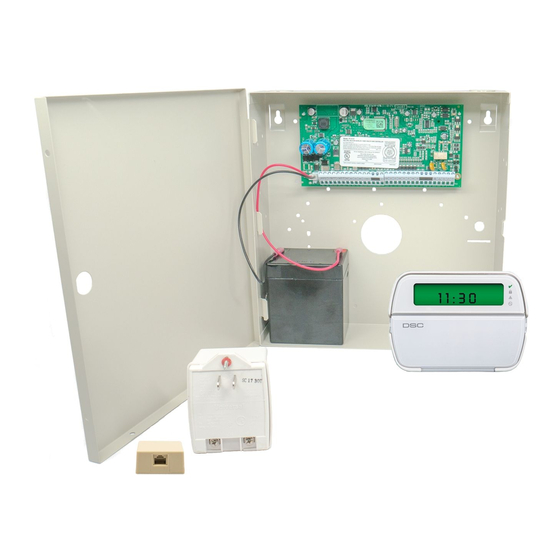
OUT Of THE BOX
Qty
1
q
Cabinet
q
Qty
1
PC Module
q
Qty
1
Installation Guide
Qty
1
q
User Manual
Qty
2
q
Cabinet Label
Qty
1
q
Cabinet Door Plug
Qty
5
q
Standoffs
q
Qty
16
5.6KΩ Resistors
q
Qty
1
2.2KΩ Resistor
Qty
1
q
1.0KΩ Resistor
Qty
1
q
Grounding Kit
SPECIFICATIONS
Temp Range:
0°C-49°C (32°F-120°F)
Humidity (max):
93%R.H.
Power Supply:
16.5VAC/40VA @60Hz
Current Draw: (Panel)
110mA (nom.)
Aux+ Output:
11.1-12.6VDC/700mA
Bell Output:
11.1-12.6VDC/700mA
Compatible Devices
Keypads
(Backward compatible with all PowerSeries keypads)
PK55XX Keypad . . . 125mA (max.)
RFK55XX Keypad . . . 135mA (max.)
LCD5511 Fixed Message LCD Keypad . . . 85mA (max.)
LED5511Z 8-zone LED Keypad . . . 100mA (max.)
PC5003C . . . 222x298x78mm (11.3x11.7x3.0in)
PC500C (residential burg only) 213x235x78mm (8.4x9.25x3.0in)
PC4050CAR (UL commercial burg) 305x 376x124mm (12.0x14.8x4.9in)
CMC-1 (UL commercial burg) 287x297x76mm (11.3x11.7x3.0in)
Suttle, SAE 14 . . . 355.6 x 362x 95mm (14x14.25x 3.75in)
Suttle, SAE 21 . . . 533.4 x 362x 95mm (21x14.25x 3.75in)
Suttle, SAE 28 . . . 711.2 x 362x 95mm (28x14.25x 3.75in)
Suttle, SAE 42 . . . 1066.8 x 362x 95mm (42x14.25x 3.75in)
Installation
Mount additional modules in cabinet using stand-offs provided, then mount cabinet in a dry, protected area with access to unswitched AC power. Install hardware
in the sequence indicated. Do NOT apply power until installation is complete.
NOTE: All wiring entry points are designated by arrows. All circuits are classified UL power limited except the battery leads. Minimum 1/4" (6.4mm) separation
must be maintained at all points between power limited and non-power limited wiring and connections.
WARNING: This manual contains information on limitations regarding product use and function and information on the limitations as to
liability of the manufacturer. The entire manual should be carefully read.
Features
On-board Zones
Hardwired Zones
Wireless Zones
Keypad Zone Support
On-board PGM Outputs
PGM Expansion
Keypads
Partitions
User Codes
Event Buffer
Transformer Required
Battery Required
Bell Output
Cabinets
PC1616
6
16 (1xPC5108)
32 (3xPC5108)
32
ü
PGM 1 - 50mA
PGM 1 - 50mA
PGM 2 - 300mA
PGM 2 - 300mA
8x50mA (PC5208)
8x50mA (PC5208)
4x500mA (PC5204)
4x500 mA (PC5204)
8
2
47 + Master Code
71 + Master Code
500 Events
500 Events
16.5VAC/40VA
16.5VAC/40VA
4Ah / 7Ah/14AHr
4Ah / 7Ah/14AHr
12V/700mA (cont)
12V/700mA (cont)
TL-250/TL300 Communicator . . . 275/350mA
GS2060/GS2065 (GPRS/GSM only) . . . 65mA
GS2060-SM (GPRS only) . . . 90mA
TL260GS/TL265GS (Ethernet/GPRS) . . . 100mA
TL260-SM (Ethernet only) . . . 100mA
TL260GS-SM (Ethernet/GPRS only). . . 120mA
PC5100 2-wire Interface 40mA plus devices to 170mA max.
RF5132-433 Wireless Receiver . . . 125mA
RF5108-433 Wireless Receiver . . . 125mA
PC5108 Zone Expander . . . 30mA
PC5200 Power Supply . . . 20mA
PC5204 Power Supply with 4 Programmable Outputs. 30mA
PC5208 Low Current Programmable Output Module . 50mA
Escort5580 Telephone Interface Module . . . 130m
*The T-Link TL-150 is not UL/ULC listed
PC1832
PC1864
8
8
64 (7xPC5108)
32
64
ü
ü
PGM 1/3/4-50mA
PGM 2-300mA
8x50mA (PC5208)
4x500mA (PC5204)
8
8
4
8
94 + Master Code
500 Events
16.5VAC/40VA
4Ah / 7Ah/14AHr
12V/700mA (cont)
Modules
Advertisement
Table of Contents

Related Manuals for DSC PC1616


Summary of Contents for DSC PC1616
-
Page 1: Compatible Devices
QR code to the right. PC1864/PC1832/PC1616 Alarm Controller v4.X Installation Guide This document provides information to meet UL Listing requirements for the PowerSeries PC1616, PC1832 and PC1864 alarm controllers. Use this document in conjunction with the PowerSeries PC1864/PC1832/PC1864 Installation Manual. -
Page 2: Safety Instructions For Service Persons
PowerSeries PC1616/PC1832/PC1864 Installation Guide Safety Instructions for Service Persons Warning: When using equipment connected to the telephone network, always follow the basic safety instructions provided with this product. Save these instructions for future reference. Inform the end-user of the safety precautions that must be observed when operating this equipment. - Page 3 Do NO T r oute an y wiring o ver cir cuit boar ds . M aintain at least 1"(25.4mm) separation. a)This equipment, Alar m Controller PC1616/1832/1864 shal l A minim um of 1/4" (6.4mm) separation mu st be maintained at all points between be installed and used within an en vironment that pr ov ides th e po wer limited wiring and all other non-po wer limited wiring.
- Page 4 These terminals supply 700mA of current at 12VDC for commercial installations and 11.1-12.6VDC for residential installations (e.g., BELL/SIREN DSC SD-15 WULF). To comply with NFPA 72 Temporal Three Pattern requirements, Program [013] Opt [8] must be ON. Note that 700mA (max.) Steady, Pulsed alarms are also supported.
- Page 5 ZONE (5600 ohm) Wireless CO detectors are also available. When installing wireless CO detectors, INPUT use only DSC model WS4913. A DSC wireless receiver model RF5132-433 v5.1 ALARM (SEOL TYPE 41) INITIATING (and higher) or DSC keypad receiver models RFK55XX-433 (xx=00/01/08/16/64) LOOP v1.2 (and higher) are required when installing wireless CO detectors.
- Page 6 Primary: 120VAC/60Hz./0.33A Secondary: 16.5VAC/40VA DSC PTD1640U, DSC PTC1640U, DSC PTD1640U-CC Plug-in, Class 2 Transformer. NOTE: Use DSC PTD1640 for Canadian installations. NOTE: For UL Listed installations, do NOT connect transformer to a receptacle controlled by a switch. - 6 -...
-
Page 7: Locating Detectors And Escape Plan
PowerSeries PC1616/PC1832/PC1864 Installation Guide Locating Detectors and Escape Plan The following information is for general guidance only and it is recommended that local fire codes and regulations be consulted when locating and installing smoke and CO alarms. Smoke Detectors Research has shown that all hostile fires in homes generate smoke to a greater or lesser extent. Experiments with typical fires in homes indicate that detectable quantities of smoke precede detectable levels of heat in most cases. -
Page 8: Ul Listed Commercial And Residential Installations
• The digital communicator shall be enabled than SIA or CID sending automatic programmed reporting codes. • The control panel shall be in the attack resistant enclosure DSC Model CMC-1 or • The security system shall be installed with the sounding device activated and the PC4050CAR communicator enabled for transmission using SIA or CID format. -
Page 9: Sia False Alarm Reduction Installations: Quick Reference
PowerSeries PC1616/PC1832/PC1864 Installation Guide SIA False Alarm Reduction Installations: Quick Reference SIA Feature Programming Section Comments Range/Default Requirement Exit Time - [005], 3rd entry Access to Entry and Exit delays for each partition and Bell Time Out for the For Full or auto arming:... -
Page 10: Regulatory Approvals
Cet appareil numérique de la classe B est conforme à la norme NMB-003 du Canada. Incidence of Harm If this equipment PC1864/PC1832/PC1616 causes harm to the telephone network, the telephone company will notify you in advance that temporary discontinuance of service may be required. -
Page 11: Limited Warranty
EULA, even if this EULA is deemed to be a modification of any previous arrangement or contract. If You do not agree to the terms of this EULA, DSC is unwilling to license the SOFTWARE PRODUCT to You, and You have no right to use it. - Page 12 PROPERTY. WARNING: DSC recommends that the entire system be completely tested on a regular basis. However, despite frequent testing, and due to, but not limited to, criminal tampering or electrical disruption, it is possible for this SOFTWARE PRODUCT to fail to perform as expected.