Table of Contents
Advertisement
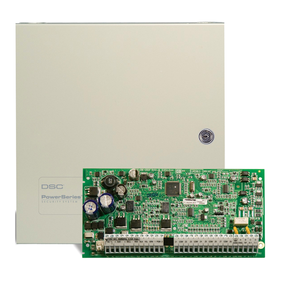
PowerSeries
PC1616/PC1832/PC1864 version 4.1
Installation Guide
Note to Installer:Center pages contain important end user information. Leave with End User.
WARNING: This manual contains information on limitations regarding product use and function and infor-
mation on the limitations as to liability the manufacturer. The entire manual should be carefully read.
Advertisement
Table of Contents

Related Manuals for DSC PC1616; PC1832; PC1864


Summary of Contents for DSC PC1616; PC1832; PC1864
-
Page 1: Installation Guide
PowerSeries PC1616/PC1832/PC1864 version 4.1 Installation Guide Note to Installer:Center pages contain important end user information. Leave with End User. WARNING: This manual contains information on limitations regarding product use and function and infor- mation on the limitations as to liability the manufacturer. The entire manual should be carefully read. -
Page 2: Table Of Contents
Table of Contents Section Description Page Installation & Wiring.................... 1 Keybus Wiring ....................2 Zone Wiring...................... 2 Zone Expanders....................2 Bell Wiring ......................2 AUX Power Wiring.................... 4 PGM Wiring...................... 4 Telephone Line Wiring..................4 Ground ......................4 Battery......................4 1.10 AC Wiring ...................... -
Page 3: Installation & Wiring
PC1832 and PC1864 control panels. This guide shall be used in conjunction with the PowerSeries PC1616/1832/1864 Reference Manual which can be obtained from your local dealer or downloaded from the DSC web site at www.dsc.com. All necessary information required to meet UL Listing requirements is included in this document. -
Page 4: Keybus Wiring
1.4 Bell Wiring These terminals supply 700mA of current at 12VDC for commercial installations and 11.1-12.6 VDC for residential installations (e.g.DSC SD-15 WULF). To comply with NFPA 72 Temporal Three Pattern requirements: Program Section [013] Opt [8] ON. NOTE: Steady, Pulsed alarms are also supported. - Page 5 12V / 7 AHr 12V / 7 AHr To EGND BLACK Terminal 16.5V /40VA DSC Model BD7-12 NON-POWER LIMITED or equivalent Battery StandbyTime: 24Hrs min. FUSE WARNING: Incorrect connections may result in PTC failure or improper operation.
-
Page 6: Aux Power Wiring
Hr. power standby. ULC Commercial Battery capacity will deteriorate with Transformer. Burglary and Fire monitoring installa- age and number of charge/discharge Use DSC PTD 1640U tions require 24 Hr. power standby. cycles. Replace every 3-5 years. for Canadian Installa- tions... -
Page 7: User Commands
Section 2: User Commands Section 2: User Commands Any system keypad can be used to program or perform any keypad command. LED keypads use status and zone indicator lights to represent alarm functions and status. The LCD keypad displays the description and status indicator lights represent alarm functions and status. This section describes basic keypad commands. -
Page 8: Programming User Codes
PowerSeries - PC1616/PC1832/PC1864 [ ][2] Trouble Display Refer to Appendix D – Trouble Conditions, for troubleshooting assistance and a detailed description of all trouble conditions. [ ][3] Alarm Memory Display The Memory light will be ON if an alarm occurred during the last armed period. Press [ ][3]. The Memory light will flash and the keypad will display the zones that went into alarm. -
Page 9: Function Keys
Section 2: User Commands [ ][6] – User Functions Press [ ][6] followed by the Master Code, then press the number corresponding to the following functions. Program Time and Date: Enter the time and date using the following format [HH:MM] [MM/DD/YY]. Program the time using military standard (e.g., 8:00 pm = 20:00 hours). -
Page 10: Programming
PC1616/1832/1864 Reference Manual for a complete description of all programmable features. 3.1 How to Program: DSC recommends filling in the Programming Worksheet with the required programming information before programming the system. This will reduce the time required to program and will help eliminate errors. -
Page 11: How To Exit Programming
Section 3: Programming 3.5 Viewing Programming LED and LCD5501Z Keypads Any programming section can be viewed from an LED or LCD5501Z keypad. When a programming section is entered, the keypad will immediately display the first digit of information pro- grammed in that section. The keypad displays the information using a binary format, accord- ing to the following chart: Press any of the Emergency keys (Fire, Auxiliary or Panic) to... -
Page 12: Programming Descriptions
PowerSeries - PC1616/PC1832/PC1864 Section 4 – Programming Descriptions The following is a brief description of the features and options available in the Power PC1616/1832/1864 control panel. Refer to the PC1616/ 1832/1864 Reference Manual for a complete description of all programming features, limitations and requirements. Section [001] to [004] Zone Definitions Option Description... - Page 13 Section 4 – Programming Descriptions [37] Night Zone: Functions like Interior Stay/Away but will remain bypassed if the user presses [ ][1] to re-activate Stay/Away zones when armed in the Stay mode [87] Delayed 24-Hour Fire (Wireless): Same as Delayed 24-Hour Fire (Hardwire) but must be used for wireless smoke detectors [88] Standard 24-Hour Fire (Wireless): Same as Standard 24-Hour Fire (Hardwire) but must be used for wireless smoke detectors Section [005] System Times...
- Page 14 PowerSeries - PC1616/PC1832/PC1864 [20] Command Output 2: Activates when a [ ][7][2] command is entered on the selected partition – Command can be programmed to require a valid access code and output can be programmed to activate for the time programmed in Section [170] or programmed to latch. [21] Command Output 3: Activates when a [ ][7][3] command is entered on the selected partition –...
- Page 15 Section 4 – Programming Descriptions Section [014] Second System Option Code Option Description ON: the system squawks the bell output once when a partition is armed, twice when disarmed. OFF: the bell output does not activate. ON: the system squawks the bell output every 10 seconds during the auto-arm pre-alert. OFF: the bell output does not activate. ON: the system will squawk the bell output once every second during Exit Delay, 3 squawks per second for the last 10 seconds.
- Page 16 PowerSeries - PC1616/PC1832/PC1864 ON: keypad backlighting enabled. OFF: keypad backlighting disabled. ON: the system temporarily enables the Keypad Blanking feature if an AC failure is detected (to preserve the back up battery). OFF: the system will operate as normal. ON: the keypad turns ON the Bypass light if zones are bypassed while the system is armed. OFF: the Bypass light turns OFF when the system is armed.
- Page 17 Section 4 – Programming Descriptions Section [020] Keypad Zone Assignment Enter the two-digit zone number to be assigned to each keypad assigned to a specific slot. Only one keypad can be assigned to a specific slot. See Keypad Assignment. Valid entries are from [00] to [64]. Section [021] Eighth System Option Code For Future Use Section [022] Ninth System Option Code...
- Page 18 PowerSeries - PC1616/PC1832/PC1864 ON: the user can manually bypass the zone using the [ ][1] command. OFF: the zone cannot be manually bypassed. ON: the partition can be armed even if the zone is violated (the zone will not affect the Ready status). OFF: the zone must be secure before arming.
- Page 19 Section 4 – Programming Descriptions Section [175] Auto-Arm Postpone Timer Program the time, in minutes, that the system will postpone automatic arming. After the programmed time, the system will attempt to auto arm again. If data [000] is programmed, the system will instead abort the auto arm sequence. Valid entries are [001] to [255]. Section [176] Cross Zone/Police Code Timer Program the time, in seconds (Cross Zone) or minutes (Police Code), that the panel will use to determine if a Cross Zone or Police Code event has occurred.
- Page 20 PowerSeries - PC1616/PC1832/PC1864 Section [311] to [318] Partition Account Numbers Program the Partition Account Number for each active partition (Section [311] for partition 1, Section [312] for partition 2 etc.). When using the Automatic SIA format, these account numbers are not used. The system will use the System Account Number for all reporting events. For all formats other than SIA, program a HEX [A] for any digit [0] in the account number being used.
- Page 21 Section 4 – Programming Descriptions Section [380] First Communicator Option Code Option Description ON: the system communicator is enabled. OFF: the communicator is disabled. ON: the system transmits alarm restorals if the zone is restored and the bell has timed out. OFF: the system transmits alarm restorals immediately when the zone is restored.
- Page 22 PowerSeries - PC1616/PC1832/PC1864 ON: the AC Failure Transmission Delay Timer will use hours. OFF: the delay will be in minutes. [7-8] For Future Use Section [401] First Downloading Option Code Option Description ON: the system answers incoming calls for downloading (either Programmed Number of Rings or Double Call). OFF: the system does not answer incoming calls for downloading.
- Page 23 Section 4 – Programming Descriptions PGM Output Option [01], [03] to [08], [11] to [22], [25] Option Description ON: the PGM output will operate normally (switch to ground when activated). OFF: the PGM output will be normally ground and switch to open collector (open circuit) when activated.
- Page 24 PowerSeries - PC1616/PC1832/PC1864 Section [701] First International Option Code Option Description ON: configures the system for 50Hz AC. OFF: configures the system for 60Hz AC. ON: the system uses the internal crystal for the internal panel clock. OFF: the system uses the AC frequency for the internal panel clock. ON: the system will inhibit arming if a Low Battery or AC trouble condition is present.
- Page 25 Section 4 – Programming Descriptions Section [900] Special Installer Instructions Section [900]: Display Panel Version Only available with LCD5500 or PK5500 keypads. The system will display the version of the control panel (for example, [0410] indicates panel version 4.10). Section [901]: Installer Walk Test The system will turn Installer Walk Test ON.
- Page 26 PowerSeries - PC1616/PC1832/PC1864 Section [993] to [999]: Factory Default Module/Panel The following Sections can be used to factory default a module or the main control panel. Enter the appropriate Section, followed by the Installer Code, followed by the Section number (E.g., [993][Installer Code][993]) Section [993]: Factory Default Alternate Communicator Section [995]:...
- Page 27 Section 5: Programming Work Sheets Section 5: Programming Work Sheets 5.1 Index to Programming Work Sheets Programming Option Page Programming Option Page [000] Keypad Enrollment ..............26 [345] Maintenance Alarm Reporting Codes........39 [001]-[004] Zone Definitions..............26 [346] Maintenance Restoral Reporting Codes ........39 [005] System Times................27 [347] Miscellaneous Maintenance Reporting Codes ......
-
Page 28: Programming Worksheets
PowerSeries - PC1616/PC1832/PC1864 5.2 Programming Worksheets Shaded programming sections indicate minimum programming trerquirements SIA FAR CP-01 defaults are indicated in gray text. Keypad Partition /Slot and Function Key Programming [000] Keypad Enrollment This must be done at each keypad requiring programming. [0] Slot address [Valid entries are 0-8 for the partition, 1-8 for the slot. - Page 29 5.2 Programming Worksheets Section Zone Def. Section Zone Def. Section Zone Def. Section Zone Def. I _ _ _ __ I _ __ __ I I _ __ _ _I _ _ __ _I I _ _ __ _I _ _ __ _ I I _ __ __ I _ __ __ I [001] [002]...
- Page 30 PowerSeries - PC1616/PC1832/PC1864 [006] Installer’s Code [007] Master Code [008] Maintenance Code Default Default Default 5555 1234 AAAA I_______I_______I_______I_______I I_______I_______I_______I_______I I_______I_______I_______I_______I Programmable Output Options Residential Burglary and Fire Bell Output Remote Operation (DLS-3 Support) Output types [03] and For Future Use For Future Use [20] cannot be used Sensor Reset [*][7][2]...
-
Page 31: About Your Security System
General System Operation pressed again to disable Door Chime. Your security system is made up of a DSC control panel, one or more keypads and 12 AM, PM – This icon indicates that the local clock is displaying 12 Hr. time. -
Page 32: Emergency Keys
Download complete User manual from www.dsc.com Emergency Keys [ ] Commands Press the (F), (A) or (P) key for 2 seconds to generate a Fire, Auxiliary or [ ][1] Bypass/Re-activate Stay/Away Zones Panic alarm. The keypad sounder will beep indicating that the alarm input has been accepted and transmission to the central station is underway. -
Page 33: Testing Your System
DSC PowerSeries Alarm System User Guide 6-digit user code or press [ ] to delete the user code. After the user code is pro- Testing Your System grammed or deleted, enter another 2-digit user to be programmed or press [#] to exit. -
Page 34: Fcc Compliance Statement
This equipment is of a type that is not intended to be repaired by the end user. cords, overloaded lighting circuits, etc. If you are uncertain about the condi- DSC c/o APL Logistics, 757 Douglas Hill Rd., Lithia Springs, GA 30122 tion of your electrical appliances or household service, have a professional Additional Information evaluate these units. - Page 35 5.2 Programming Worksheets [013] First System Options Normally Closed Loops End-of-line Resistors Double End-of-line Resistors Single End-of-line Resistors Panel shows all Troubles when armed Panel shows only Fire Troubles when armed Tampers/Faults do not show as open Tampers/Faults show as open Auto Arm Schedule in [*][6] and installers Auto-arm Schedule in Installer Programming Only Audible Exit Fault Enabled...
- Page 36 PowerSeries - PC1616/PC1832/PC1864 [017] Fifth System Options WLS Key Does NOT use Access Codes WLS Key Uses Access Codes RF Jam Log after 5 Minutes RF Jam Log after 30 Seconds Audible RF Jam Trouble Beeps Silent RF Jam Trouble Beeps Double Hit Enabled Double Hit Disabled Late to Close Enabled...
- Page 37 5.2 Programming Worksheets [023] Tenth System Options Fire Key Beeps Only Fire Key Beeps and Sounds Bell 200 Baud Open/Close Identifier Toggle ON 200 Baud Open/Close Identifier Toggle OFF Test Transmission While Armed Only Test Transmission While Armed/Disarmed Test Transmission in Hours Test Transmission in Days Switching from AWAY to STAY disabled AWAY to STAY toggle Option Permitted...
- Page 38 PowerSeries - PC1616/PC1832/PC1864 [101]-[164] Zone Attributes Zone Attribute Defaults (Y = Option ON; N = Option OFF): Bold entries are opposite for SIA CP-01 Attribute: Audible Steady Chime Bypass Force* Swing Tx. Delay Wireless Zn Cross Zn Silent Pulsed Zone Type: 00 Null Zone 01 Delay 1 02 Delay 2...
- Page 39 5.2 Programming Worksheets Section Zone # Zone Audible/ Steady/ Chime Bypass Force* Swing Tx. Delay Wireless Cross Zn Type** Silent Pulsed [117] I________I I________| I________| I________| I________| I________| I________| I________I I________I [118] I________I I________| I________| I________| I________| I________| I________| I________I I________I [119] I________I...
-
Page 40: System Timers
PowerSeries - PC1616/PC1832/PC1864 System Timers [165] Maximum Dialing Attempts to Each Telephone Number Default 005 Valid entries are 001-005 attempts I_______I_______I_______I For UL Listed Installations, 5-10 dialing attempts are required. [166] Post Dial Wait for Handshake (All Formats) Default 040 Valid entries are 001-255 seconds I_______I_______I_______I [167] T-LINK Interface Communications Wait for Acknowledge... - Page 41 5.2 Programming Worksheets No Activity Arming Timers - Default is [000] for all partitions Section Partition [191] Valid entries are 001-255 minutes, 000 to disable I_______I_______I_______I [192] Valid entries are 001-255 minutes, 000 to disable I_______I_______I_______I [193] Valid entries are 001-255 minutes, 000 to disable I_______I_______I_______I [194] Valid entries are 001-255 minutes, 000 to disable...
-
Page 42: Reporting Codes
PowerSeries - PC1616/PC1832/PC1864 Communications When using T-Link, [301] First Telephone Number (32 Digits) program DCAA as I_____I_____I_____I_____I_____I_____I_____I_____I_____I_____I_____I_____I_____I_____I_____I_____I_____I_____I_____I_____I_____I_____I_____I_____I_____I_____I_____I_____I_____I_____I_____I_____I the phone number. [302] Second Telephone Number (32 Digits) I_____I_____I_____I_____I_____I_____I_____I_____I_____I_____I_____I_____I_____I_____I_____I_____I_____I_____I_____I_____I_____I_____I_____I_____I_____I_____I_____I_____I_____I_____I_____I_____I [303] Third Telephone Number (32 Digits) I_____I_____I_____I_____I_____I_____I_____I_____I_____I_____I_____I_____I_____I_____I_____I_____I_____I_____I_____I_____I_____I_____I_____I_____I_____I_____I_____I_____I_____I_____I_____I_____I [304] Call Waiting Cancel String (6 Digits) - This feature is activated in Section 382 Opt 4 Default = DB70EF Program unused digits with Hex F I_______I_______I_______I_______I_______I_______I... - Page 43 5.2 Programming Worksheets [324]-[327] Alarm Restoral Reporting Codes, Zones 01-64 Section [324] Zone 01 Zone 02 Zone 03 Zone 04 Zone 05 Zone 06 Zone 07 Zone 08 I_______I_______I I_______I_______I I_______I_______I I_______I_______I I_______I_______I I_______I_______I I_______I_______I I_______I_______I Zone 09 Zone 10 Zone 11 Zone 12 Zone 13...
- Page 44 PowerSeries - PC1616/PC1832/PC1864 [334]-[337] Tamper Restoral Reporting Codes, Zones 01-64 Section [334] Zone 01 Zone 02 Zone 03 Zone 04 Zone 05 Zone 06 Zone 07 Zone 08 I_______I_______I I_______I_______I I_______I_______I I_______I_______I I_______I_______I I_______I_______I I_______I_______I I_______I_______I Zone 09 Zone 10 Zone 11 Zone 12 Zone 13...
- Page 45 5.2 Programming Worksheets [344] Miscellaneous Opening (Disarming) Reporting Codes I_______I_______I Opening by Duress Code 33 I_______I_______I Opening by Duress Code 34 I_______I_______I Opening by Master Code 40 Opening by Supervisory Code 41 I_______I_______I I_______I_______I Opening by Supervisory Code 42 Auto Arm Cancellation I_______I_______I I_______I_______I Special Opening...
- Page 46 PowerSeries - PC1616/PC1832/PC1864 Call Direction Options [351]-[358] Alarm/Restore Communicator Call Directions Option 1 Option 2 Option 3 Option 4 Option 5 Options 6,7,8 Section Partition 1st Telephone 2nd Telephone Not Used Not Used Alt Comm Future Use Number (Def ON) Number (Def OFF) (Def OFF) (Def OFF)
- Page 47 5.2 Programming Worksheets [377] Communication Variables Default Swinger Shutdown (Alarms and Rest) 001-014 Transmissions I___ __I__ __I___ Swinger Shutdown (Tampers and Rest) 001-014 Transmissions, 000=disabled I___ __I__ __I___ Swinger Shutdown (Maint and Rest) 001-014 Transmissions, 000=disabled I___ __I__ __I___ Communication Delay 001-255 seconds I___ __I__...
- Page 48 PowerSeries - PC1616/PC1832/PC1864 [382] Third Communicator Options Contact ID Partial Closing Identifier is “5” Contact ID Partial Closing Identifier is “4” Alarm Communications Enabled During Walk Test* Alarm Communications Disabled During Walk Test Communication Cancelled Message Enabled Communication Cancelled Message Disabled (ON for SIA CP-01) Call Waiting Cancel Enabled** Call Waiting Cancel Disabled...
- Page 49 5.2 Programming Worksheets [501]- [554]Programmable Output Attributes Program only the following attributes for the PGM options listed. All others will be ignored. PGM options are programmed in [009], [010] & [011]. PGM Attribute Defaults (Y = Attribute ON; N = Attribute OFF): Attribute: Not used Not used True Output Follows Timer Code Req.
- Page 50 PowerSeries - PC1616/PC1832/PC1864 Section PGM Output Type* Main Board [501] I________I I________| I________| I________| I________| I________| I________| I________I [502] I________I I________| I________| I________| I________| I________| I________| I________I Main Board / PC5208 [503] ** I________I I________| I________| I________| I________| I________| I________| I________I [504] ** I________I...
- Page 51 5.2 Programming Worksheets INTERNATIONAL PROGRAMMING [700] Automatic Clock Adjust Default = 60 Valid Entries 00-99 Seconds |________|_________| [701] First International Options 50 Hz AC 60 Hz AC Time Base - Internal Crystal Time Base - AC Line AC/DC Arming Inhibit Enabled AC/DC Arming Inhibit Disabled All System Tampers Require Installer Reset All System Tampers Follow Restore...
- Page 52 PowerSeries - PC1616/PC1832/PC1864 Special Installer Functions [900] Panel Version Displayed [901] InstallerWalk Test Mode Enable/Disable [902] Module Supervision Reset [903] Module Supervision Field [904] Wireless Module Placement Test [905] - [909] For Future Use [990] Installer Lockout Enable [991] Installer Lockout Disable [992] For Future Use [993] Restore Alternate Communicator to Default Programming [994] For Future Use...
- Page 53 Appendix A: Reporting Codes Appendix A: Reporting Codes The following tables contain Contact ID and Automatic SIA format reporting codes. For more information on reporting code formats and notes about individual reporting codes, (see Section 5.6 Communicator Programming PWS Sect 6). Contact ID The first digit (in parentheses) will automatically be sent by the control.
- Page 54 PowerSeries - PC1616/PC1832/PC1864 Automatic Dialer SIA Auto Section # Reporting Code Code Sent When... Contact ID Direction* Rep Codes** Codes [345]-[346] Auxiliary Power Trouble/ Aux voltage supply trouble/restoral MA/R (3) 12 YP-00/YQ-00 Rest. [345] TLM Failure Telephone line monitoring trouble MA/R (3) 51 LT-01...
- Page 55 The local annunciation devices may be any combination of the following key- •The control panel must be in the attack resistant enclosure (DSC Model CMC- pads, as long as there is at least one LCD keypad in the installation (Model 1 or PC4050CAR).
- Page 56 PowerSeries - PC1616/PC1832/PC1864 Appendix C: SIA False Alarm Reduction SIA Feature Comments Range/Default Require- Programming Section ment Exit Time Access to Entry and Exit delays for each partition and Bell Time Out for the system For Full or auto arming: Required [005], 3rd entry Range:45- 255 seconds...
- Page 57 Appendix D: Troubleshooting Guide Appendix D: Troubleshooting Guide Testing: • Power up system • Program options as required (See Programming Section) NOTE: For advanced programming refer to the PC1616/1832/1864 Reference Manual • Violate, then restore zones • Verify correct Reporting Codes are sent to the Central Station Troubleshooting: LCD Programmable-Message Keypad •...
- Page 58 PowerSeries - PC1616/PC1832/PC1864 Trouble Cause Troubleshooting Trouble [1] Service Required Press [1] to determine specific trouble [1] Low Battery Main panel battery less than 11.1VDC NOTE: If battery is new allow 1 Hr. for battery to charge. • Verify voltage measured across AC terminals is 16-18 VAC. NOTE: This trouble condition will not Replace transformer if required.
- Page 59 Appendix D: Troubleshooting Guide Trouble Cause Troubleshooting Trouble [2] AC Failure No AC at panel AC input Verify voltage measured across AC terminals is 16-18VAC. Replace terminals transformer if required. Trouble [3] Telephone Line Trouble Phone Line Voltage at TIP, RING on main •...
- Page 60 PowerSeries - PC1616/PC1832/PC1864 Trouble Cause Troubleshooting Trouble [5] Zone Fault (Cont.) One or more wireless devices have not • If the trouble occurs immediately, a conflict with a hard wired checked in within the programmed time zone exists: • The zone being used is already assigned to a PC5108 zone expander •...
- Page 61 NOTES...
- Page 62 NOTES...
-
Page 63: Limited Warranty
DSC. Cus- • Inadequate Installation tom products are only warranted to the extent that they do not function upon delivery. In such cases, DSC A security system must be installed properly in order to provide adequate protection. Every installation can replace or credit at its option. -
Page 64: Additional Information
DSC c/o APL Logistics, 757 Douglas Hill Rd., Lithia Springs, GA 30122 ing the equipment off and on, the user is encouraged to try to correct the interference by one...