Hitachi NT 65GB Technical Data And Service Manual
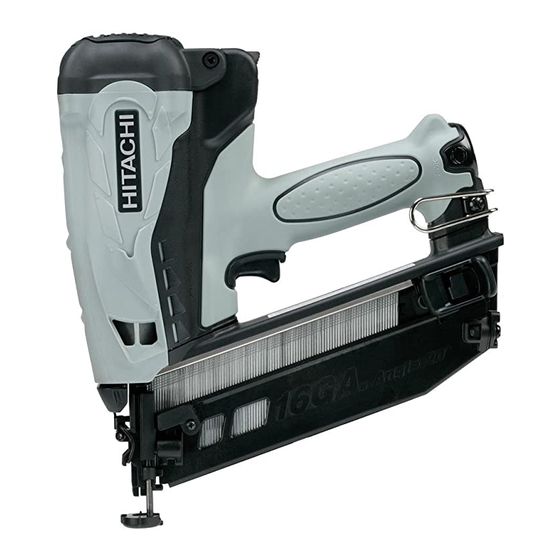
Gas finish nailer
Hide thumbs
Also See for NT 65GB:
- Instruction and safety manual (112 pages) ,
- Handling instructions manual (104 pages) ,
- Instruction and safety manual (34 pages)
Table of Contents
Advertisement
Advertisement
Table of Contents
Troubleshooting

Related Manuals for Hitachi NT 65GB


Summary of Contents for Hitachi NT 65GB
- Page 1 NT 65GB GAS FINISH NAILER NT 65GB Aug. 2011 E047...
- Page 2 REMARK: Throughout this TECHNICAL DATA AND SERVICE MANUAL, a symbol(s) is(are) used in the place of company name(s) and model name(s) of our competitor(s). The symbol(s) utilized here is(are) as follows: Competitors Symbols Utilized Company Name Model Name Paslode 900600 (USA)/IM65AF16 (EU)
-
Page 3: Table Of Contents
Cylinder Head Section and Handle Section ------------------------------------------------------ 26 10-3. Disassembly and Reassembly of the Cylinder Head Section --------------------------------------29 10-4. Disassembly and Reassembly of the Housing Section ----------------------------------------------31 10-5. Disassembly and Reassembly of the Handle Section -----------------------------------------------42 11. STANDARD REPAIR TIME (UNIT) SCHEDULES-----------------------------------------------------------48 Assembly Diagram for NT 65GB... -
Page 4: Product Name
Model NT 65GB Gas Nailer to expand our market share. Finish The main features of the Model NT 65GB are as follows: (1) Compact and lightweight, with lithium-ion batteries (2) Battery located at end of the handle for better balance... -
Page 5: Specifications
• UC 3SFL Charger • UC 3SFL Charger 5-2. Explanation of the Nailing Action To meet the requirements of "ANSI SNT-101-2002" (USA), the Model NT 65GB is equipped with a FULL SEQUENTIAL ACTUATION MECHANISM. • FULL SEQUENTIAL ACTUATION MECHANISM First, press the pushing lever against the wood, and then pull the trigger to drive the nail. After nailing once, nailing will not be possible again until you release the trigger and press the lever again. -
Page 6: Nail Selection
Fig. 2 below compares the output energy range of the Model NT 65M2 and other pneumatic nailers, with that of the Model NT 65GB Gas Finish Nailer. The output energy of the Model NT 65GB changes within an operating range of 5.4 kg/cm (76.8 psi) -
Page 7: Comparison With Similar Products
6. COMPARISON WITH SIMILAR PRODUCTS Maker HITACHI Model NT 65GB Item Weight 1.8 kg (4.0 lbs.) 2.3 kg (5.1 lbs.) (tool, battery, fuel cell) 268 x 282 x 85 mm 273 x 292 x 90 mm Dimensions (L x H x W) (10-5/8 “... -
Page 8: Precautions On Sales Promotion
7. PRECAUTIONS ON SALES PROMOTION In the interest of promoting the safest and most efficient use of the Model NT 65GB Gas Finish Nailer by all of our customers, it is very important when concluding a sale that the salesperson carefully ensure that the buyer seriously recognizes the importance of the Handling Instructions, and fully understands the precautions listed on the Warning Label attached to each tool. - Page 9 [For Europe] Fuel cell [For the USA and Canada] OK Befestigung D-47802 Krefeld, Germany (www.okbefestigung.de) PATENT PENDING Contents: Compressed flammable liquefied gas Made in Germany 18 g/30 ml DANGER - EXTREMELY FLAMMABLE CONTENTS UNDER PRESSURE. • Keep away from temperatures over 50 C <...
-
Page 10: Related Laws And Regulations
7-3. Related Laws and Regulations As nailers and staplers are designed to instantaneously drive nails and staples, there is an ever- present danger of misfiring and possibly serious injury. Accordingly, close attention to handling is absolutely necessary at all times. Carefully ensure that the customer is fully aware of the precautions listed in the Handling Instructions provided with each unit. - Page 11 Cautions on handling the fuel cell: First Aid: If contents are inhaled, move to an area with fresh air. Contact a doctor if symptoms persist. If contents come in contact with skin, wash affected area with soap and warm water, then apply skin cream.
-
Page 12: Mechanism And Principle Of Operation
Model NR 90GC2. Its principle of operation is completely different from that of a pneumatic nailer, except for the magazine section. The Model NT 65GB is equipped with a fuel cell and a battery to output combustion energy, in addition to such electric components as electric circuits, a motor, and electric switches. - Page 13 Head section (Cylinder head section) Motor mount Filter Cover [1A] Handle section Filter Mesh [2] Motor Top Cover [4A] Actuator [56] Cylinder Head [7A] Battery [58] Spark Plug (A) [5] Spark switch Motor spring Fan [11] Combustion chamber Chamber [16] Piston [27] Cylinder Ass'y (A) [104A] Housing [30A]...
-
Page 14: Principle Of Operation
8-2. Principle of Operation (1) Before nailing Fuel is not charged into the nailer in the initial state. The combustion chamber is Combustion released to the atmosphere (Fig. 4). chamber Fuel cell Fan [11] (2) When nailing 1) Push up Pushing Lever (A) [82].. Chamber [16] The nailer then starts operation in the following order (Fig. - Page 15 2) Holding down the Trigger [71] makes the spark switch turn on. The spark plug in the combustion chamber then Spark Plug (A) [5] discharges (Fig. 6). The fuel thus burns and a sudden expansion occurs. The Piston [27] is Combustion Spark switch chamber...
- Page 16 Filter Mesh [2] (4) Discharge and cooling When you stop pressing Pushing Lever (A) [82], the Chamber [16] is placed in its initial state and the sealing by Piston Ring (B) [17] is Piston Ring (B) [17] released. When the Fan [11] rotates, Fan [11] air passes through the Filter Mesh [2], enters the combustion chamber, and...
- Page 17 (5) Full sequential action mechanism Press Pushing Lever (A) [82] against the workpiece and move the Chamber Tip of Trigger [16] to the uppermost position. The Stopper [75] nailer will then operate only when you hold down the Trigger [71]. The nailer will not operate if you press Pushing Spark switch Lever (A) [82] insufficiently or press it...
-
Page 18: Troubleshooting Guide
9. TROUBLESHOOTING GUIDE 9-1. Problems Caused by Improper Handling The table below lists the problems that may occur. Note that improper handling causes these problems, not any nailer abnormality. Therefore, please instruct the customers to use the nailer properly according to the table. Improper handling Problem Cause... - Page 19 Insert the stem of the fuel cell into the hole on the adapter. To attach the metering valve to a fuel cell: (1) Separate the metering valve and cap from the gas cartridge. Stem Adapter [20] Fuel cell (2) Press the front side of the metering valve forward (stem side) and downward.
-
Page 20: Troubleshooting And Corrective Action
9-2. Troubleshooting and Corrective Action (1) Troubleshooting and correction action for gas nailers The mechanism used by a gas nailer to produce output is completely different from that used by a pneumatic nailer. The table below lists the troubleshooting and correction action to take for gas nailers. - Page 21 Controller [95] Connection between Internal Wire (A) [60A] and the Controller [95] Fig. 15 Support (B) [59] with adhesive Fig. 16 -18-...
- Page 22 <Continued> Problem Possible cause Inspection method Corrective action No combustion <Electric section> occurs. Continued • The Battery [58] is not • Set the Battery [58] • No spark occurs. (Check set properly. properly. for sparking according to • The Battery [58] is faulty. •...
- Page 23 Spark Plug (A) [5] Clean this area in particular. Fan [11] Fig. 17 -20-...
- Page 24 (2) Troubleshooting and corrective action for general-purpose nailers Problem Possible cause Inspection method Corrective action <Nails> Nails cannot • The magazine is not • Check whether the • Use the specified nails. be driven. loaded with specified magazine is loaded •...
- Page 25 Problem Possible cause Inspection method Corrective action <Output section> Nails cannot • The piston bumper is • Pull the nail feeder • Replace the piston be driven. abnormal (dislocated, backward and perform idle bumper. (Continued) deformed or damaged). driving. • Piston Ring (B) [17] of the Check whether the driver •...
-
Page 26: Checking For Sparking And Corrective Action
9-3. Checking for Sparking and Corrective Action The following five items are the main causes of no combustion. 1. The fuel cell is abnormal. → (Replace the fuel cell with a new one.) 2. The battery is abnormal. → (Check the battery.) 3. -
Page 27: Regrinding The Driver Blade
• Apply oil (Gas Nailer Lubricant) (Code No. 885-246 or 885-546) to the areas shown in Fig. 20. • Oil required: Hitachi Gas Nailer Lubricant 8 oz. (250 cc) oil feeder (Code No. 885-246 or 885-546) • Use the cleaner (Code No. 885245) to clean such inner parts. - Page 28 Oil application areas Piston Ring (B) [17] Mount Sleeve Thoroughly apply oil. Thoroughly apply oil. Cylinder Head [7A] Apply oil to the diagonally shaded areas. Cylinder Ass'y (A) [104A] • Outside: Piston ring groove Apply oil to the diagonally shaded areas. •...
-
Page 29: Disconnecting And Reconnecting Wiring Between The Cylinder Head Section And Handle Section
10-2. Disconnecting and Reconnecting Wiring between the Cylinder Head Section and Handle Section The Model NT 65GB consists of three sections—the cylinder head section, housing section, and handle section. The wiring between the cylinder head section and handle section must be disconnected before disassembling and reassembling each section. - Page 30 Filter Cover [1A] Hex. Socket Hd. Bolt (W/Flange) M5 x 10 [3] Filter Mesh [2] Top Cover [4A] Hex. Shoulder Bolt M5 [24] Nylock Hex. Socket Hd. Bolt M4 x 12 [6] Packing [19] Adapter [20] Cylinder Head [7A] Fig. 22 -27-...
- Page 31 Spark plug cable Wiring connected to the motor Spark Plug (A) [5] Support (B) [59] Machine Screw M4 x 10 [62] Connector of Packing [19] the motor Fig. 23 (b) Reassembly Conduct reassembly by reversing the disassembly procedure. Note the following points: •...
-
Page 32: Disassembly And Reassembly Of The Cylinder Head Section
10-3. Disassembly and Reassembly of the Cylinder Head Section (1) Disassembly and reassembly of the Cylinder Head [7A] and related parts [Tools required] • Hex. bar wrench (3 mm (0.118”) • Spanner (5.5 mm (0.217")) x 2 • Socket wrench (8 mm (0.314")) •... - Page 33 (b) Reassembly Conduct reassembly by reversing the disassembly procedure. Note the following points: • Attach the Shaft Rubber Washer [22] to the Cylinder Head [7A], and apply the specified oil (Code No. 885-546 or 885-246). • Apply the designated oil (Code No. 885-546 or 885-246) Piston Ring (B) [17] and the mount sleeve.
-
Page 34: Disassembly And Reassembly Of The Housing Section
10-4. Disassembly and Reassembly of the Housing Section (1) Disassembly and reassembly of the housing section and handle section (See Fig. 27.) [Tool required] • Hex. bar wrench (3 mm) (a) Disassembly • Remove the cylinder head section from the main body. (Fig. 27) Removing the Hex. - Page 35 (2) Disassembly and reassembly of the housing section (See Fig. 29.) [Tools required] • Hex. bar wrench (3 mm (0.118")) • Spanner (8 mm) or slender hd. pliers • Roll pin puller (3 mm (0.118")) • Phillips screwdriver • Retaining ring puller for C-type holes •...
- Page 36 Hex. Socket Hd. Bolt M4 x 16 [13] Chamber Head [14] Chamber Spring [73] Gasket [15] Seal Lock Hex. Socket Hd. Bolt M4 x 10 [74] Chamber [16] Pushing Lever Arm [77] Pushing Lever Piece [78A] Nylon Nut M5 [44] O-Ring (S-8) [79] Adjuster [80] Piston Ring (B) [17]...
- Page 37 • Firmly insert the Chamber Spring [73] into the spring insertion part of the Pushing Lever Arm [77]. • Secure the Pushing Lever Arm [77] to the Chamber [16] by tightening the Seal Lock Hex. Socket Hd. Bolt M4 x 10 [74], so that the contact surface of the Pushing Lever Arm [77] contacts the upper side of the Chamber Stop Rubber [43], thereby preventing removal of the Chamber Spring [73] from the Cylinder [42A] with support provided by the Pushing Lever Arm [77].
- Page 38 (3) Disassembly and reassembly of the cylinder ass'y (a) Disassembly • Use the retaining ring puller for C-type holes to remove the Retaining Ring For D40 Hole [18]. Insert a finger into the outlet of Cylinder Ass'y (A) [104A] and push the tip of the Piston [27]straight up.
- Page 39 Cylinder Ass'y (A) [104A] Piston Bumper [28] Roll pin puller Roll pin puller Piston [27] Direction of exhaust Push in here. Fig. 32 -36-...
- Page 40 (b) Reassembly Conduct reassembly by reversing the disassembly procedure. Note the following points: • Set the Muffler [49] at the concave section between the claws of the Buffer Cover [48]. • Drop the Piston Bumper [28] into Cylinder Ass'y (A) [104A] by facing its stepped side inward and using the handle of a hammer to push it in until it passes through the stopper portion.
- Page 41 Split of Piston Ring (A) [26] “(1)” Cylinder Ass'y (A) [104A] Direction of exhaust Split of the Piston Ring (A) [26] “(2)” Push lightly. Piston Ring (A) [26] “(1)” Piston Ring (A) [26] “(2)” Piston [27] Chamfered side of the driver blade Direction of exhaust Direction...
- Page 42 • Insert the Retaining Ring For D40 Hole [18] into Cylinder Ass'y (A) [104A] so that the split part of the Retaining Ring For D40 Hole [18] faces the discharge port side. Retaining Ring For D40 Hole [18] Face the split of the Retaining Ring For D40 Hole [18] toward the no-concave portion of Cylinder Ass'y (A) [104A] Cylinder Ass'y (A) [104A].
- Page 43 (b) Reassembly • Fit Gasket [15] into the groove of the Chamber Head [14] and mount it on the Chamber [16]. Do not allow the Gasket [15] to protrude from the groove. Therefore, carefully ensure the proper mounting direction of the Gasket [15]. (Fig. 37) Chamber Head [14] Gasket [15] Convex portion of...
- Page 44 (6) Disassembly and reassembly of the Blade Guide peripherals [Tools required] • Hex. bar wrench (3 mm (0.118”)) • Pin puller • Hammer (a) Disassembly • Turn the Adjuster [80] and remove Pushing Lever (A) [82]. • Remove the Seal Lock Hex. Socket Hd. Bolt M4 x 12 [33], and then remove the Blade Guide [32] and related parts from the Cylinder [42A].
-
Page 45: Disassembly And Reassembly Of The Handle Section
10-5. Disassembly and Reassembly of the Handle Section (1) Disassembly and reassembly of Handle (A) [68A], Handle (B) [40A], the magazine cover ass’y, and related parts (See Fig. 40.) [Tools required] • Roll pin puller • Phillips screwdriver (a) Disassembly •... - Page 46 Tapping Screw (W/Flange) D4 x 16 (Black) [39] Tapping Screw (W/Flange) D4 x 20 (Black) [57] Item No. [57] [39] Tapping Screw Tapping Screw Description (W/Flange) (W/Flange) D4 x 20 (Black) D4 x 16 (Black) Dimensions Number of screws/bolts Tightening torque 1.5 ±...
- Page 47 Actuator ass’y Trigger Spring [70] Stopper Spring (B) Trigger Stopper [75] Trigger [71] Magazine cover ass’y Pin D3 x 20 [76] Cord Cover Plate [72] B - B (No magazine indication) A - A Handle (A) [68A] Terminal Support [69] Handle (B) [40A] Handle (A) [68A] Lock Nut M4...
- Page 48 (2) Disassembly and reassembly of the magazine cover ass'y, nail feeder, and related parts (See Fig. 42.) [Tools required] • Phillips screwdriver • Roll pin puller (2.5 mm (0.098") dia.) (3 mm (0.12") dia.) (a) Disassembly • Remove the nail feeder and the Nail Rail [97] by hand. •...
- Page 49 Machine Screw M5 x 15 (Black) [88] Bolt Washer M5 [87] Magazine Cover [86] Tapping Screw (W/Flange) D4 x 20 (Black) [57] Internal Wire (A) [60A] Tapping Screw (W/Flange) D4 x 12 (Black) [96] Controller [95] Prism [94] Roll Pin D3 x 16 [89] Ribbon Spring [90] Nail Rail [97] Nylon Nut M5 [44]...
- Page 50 (b) Reassembly Conduct reassembly by following the procedure below. • Mount the Ribbon Spring [90] on Nail Feeder (B) [91], and then drive the Roll Pin D3 x 16 [89]. Mount Nail Feeder (A) [92] and Stopper Spring (C) [93] on Nail Feeder (B) [91], and then drive the Roll Pin D2.5 x 26 [98].
-
Page 51: Standard Repair Time (Unit) Schedules
11. STANDARD REPAIR TIME (UNIT) SCHEDULES Variable MODEL 70 min. Fixed Work Flow Cylinder Head NT 65GB Motor Ass'y Rubber Plate Piston Spark Plug (A) Piston Ring Piston Ring (A) x 2 (B) x 2 Piston Ring (B) x 2... - Page 52 LIST NO. E047 GAS FINISH NAILER 2011 · 8 · 18 Model NT 65GB (E3) 104A 106B 7A 23B 25B 506A 40A 67A 68A...
- Page 53 PARTS NT 65GB ITEM ITEM CODE NO. CODE NO. DESCRIPTION REMARKS USED USED 886-664 FILTER COVER 886-344 FILTER MESH 886-347 HEX. SOCKET HD. BOLT (W/FLANGE) M5 X 10 886-335 TOP COVER 885-333 SPARK PLUG (A) 880-630 NYLOCK HEX. SOCKET HD. BOLT M4 X 12...
- Page 54 PARTS NT 65GB ITEM CODE NO. DESCRIPTION REMARKS USED 886-293 BUFFER PLATE 886-294 O-RING 886-292 MESH 886-332 CELL PIN 886-333 PIPE RUBBER 886-326 ACTUATOR 302-086 TAPPING SCREW (W/FLANGE) D4 X 20 (BLACK) 326-299 BATTERY EBM 315 (EUROPE, AUS, NZL) 326-263...
-
Page 55: Standard Accessories
PARTS NT 65GB ITEM CODE NO. DESCRIPTION REMARKS USED 886-606 PUSHING STOPPER (B) 886-619 PUSHING STOPPER SPRING 886-607 PUSHING STOPPER COVER (B) 306-371 TAPPING SCREW (W/FLANGE) D3 X 10 (BLACK) 104A 886-550 CYLINDER ASS'Y (A) INCLUD. 42A, 46-53 875-638 O-RING (S-12)