Table of Contents
Advertisement
Quick Links
Q Model
Ice Machines
Installation
Use and Care Manual
Q460/Q660/Q1060/
Q1090
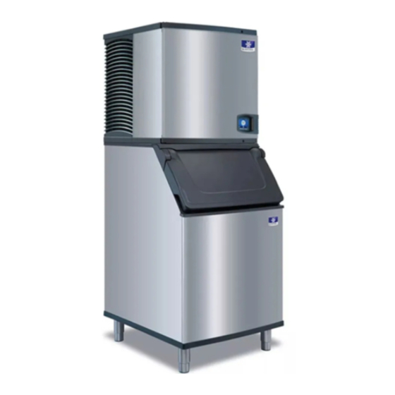
Thank you for selecting a Manitowoc Ice Machine, the dependability leader in ice making equipment and related
products. With proper installation, care and maintenance, your new Manitowoc Ice Machine will provide you with many
years of reliable and economical performance.
Part Number 000001759
01/07
Advertisement
Table of Contents

Related Manuals for Manitowoc Q460


Summary of Contents for Manitowoc Q460
- Page 1 Q460/Q660/Q1060/ Q1090 Thank you for selecting a Manitowoc Ice Machine, the dependability leader in ice making equipment and related products. With proper installation, care and maintenance, your new Manitowoc Ice Machine will provide you with many years of reliable and economical performance.
-
Page 2: Safety Notices
If you to read the Caution statement before proceeding, enounter problems not covered by this manual, do and work carefully. not proceed, contact Manitowoc Ice, Inc. We will be happy to provide assistance. Important Routine adjustments and maintenance procedures outlined in this manual are not covered by the warranty. -
Page 3: Table Of Contents
Dispenser ........... . Manitowoc Cleaner and Sanitizer ....... . . - Page 4 Q460/Q660/Q1060 ........
- Page 5 (continued) Table of Contents Section 4 Maintenance Interior Cleaning and Sanitizing ........General .
- Page 6 (continued) Table of Contents Blank Page Part Number 000001759...
-
Page 7: General Information
Section 1 General Information Section 1 General Information Model Numbers How to Read a Model Number This manual covers the following models: # CUBE SIZE CON DENSER T YPE Self-Contained Air-Cooled Remote AIR-COOLED 2 DICE QD0462A AIR-COOLED 9 REMOTE 4 HALF-DICE QY0464A AIR-COOLED QD0662A... -
Page 8: Accessories
As your business grows and your ice needs increase, DISPENSER Manitowoc stack-on capability can double your daily ice production without using additional floor space. A counter-top dispenser is ideal for cafeterias and many types of self-service facilities. Manitowoc auto-fill, floor-... -
Page 9: Model/Serial Number Location
These listed on the MODEL/SERIAL NUMBER DECAL affixed numbers are required when requesting information from to the ice machine, remote condenser and storage bin. your local Manitowoc distributor, or Manitowoc Ice, Inc. Model/Serial Plate Ice Machine SV1600... -
Page 10: Warranty
If you do not return your OWNER WARRANTY 4. Premium labor rates due to holidays, overtime, REGISTRATION CARD, Manitowoc will use the date of etc.; travel time; flat rate service call charges; factory shipping as the first day of warranty coverage for mileage and miscellaneous tools and material your new ice machine. -
Page 11: Installation Instructions
111.7 cm Warning All Manitowoc ice machines require the ice storage system (bin, dispenser, etc.) to incorporate an ice deflector. Prior to using a Manitowoc ice machine on a non- Manitowoc storage system, contact manufacturer to assure their ice deflector is compatible with Manitowoc ice machines. -
Page 12: Remote Condenser Dimensions
Installation Instructions Section 2 Remote Condenser Dimensions JC1096 SV1297 Part Number 000001759... -
Page 13: Location Of Ice Machine
A stacking kit is required for stacking two ice machines. select another location. Installation instructions are supplied with the stacking kit. • The location must be free of airborne and other contaminants. Stacked Q460/Q660/ Stacked Self-Contained • The air temperature must be at least 1.6°C, but must Q1060 Remote Air-Cooled not exceed 43.4°C. -
Page 14: Leveling The Ice Storage Bin
Installation Instructions Section 2 Leveling the Ice Storage Bin Air-Cooled Baffle 1. Screw the leveling legs onto the bottom of the bin. The air-cooled baffle prevents condenser air from recirculating. To install: 2. Screw the foot of each leg in as far as possible. 1. -
Page 15: Electrical Service
(when the electrical when it senses an unexpected loss of power, load is highest). presumably to ground. Manitowoc Ice, Inc. does not recommend the use of a GFCI/GFI circuit protection with our equipment. If code requires the use of a GFCI/GFI Warning then you must follow the local code. -
Page 16: Self Contained Ice Machine
Installation Instructions Section 2 Q460 - Q1090 Ice Machines Air-Cooled Remote Voltage Phase Maximum Fuse/ Minimum Circuit Maximum Fuse/ Minimum Circuit Cycle Machine Circuit Breaker Amps Circuit Breaker Amps 230/1/50 Q460 230/1/50 Q660 230/1/50 15.6 14.6 Q1060 230/1/50 14.6 Q1090... -
Page 17: Water Supply And Drain Requirements
Drain lines must have a 2.5 cm drop per meter of run and must not create traps. Important If you are installing a Manitowoc water filter system, • The floor drain must be large enough to refer to the Installation Instructions supplied with the accommodate drainage from all drains. -
Page 18: Water Supply And Drain Line Sizing/Connections
Installation Instructions Section 2 WATER SUPPLY AND DRAIN LINE SIZING/CONNECTIONS ! Caution Plumbing must conform to state and local codes. Tubing Size Up to Ice Location Water Temperature Water Pressure Ice Machine Fitting Machine Fitting 0.6°C Min. 1.38 bar Min. 3/8"... -
Page 19: Remote Condenser/Line Set Installation
Section 2 Installation Instructions Remote Condenser/Line Set Installation Remote Single Air Temperature Around the Condenser Minimum Maximum Ice Machine Circuit Line Set* Condenser -29°C 49°C Q1060 RT-20-R404A Q1090 JC1096 RT-35-R404A REMOTE ICE MACHINE REFRIGERANT CHARGE RT-50-R404A Each remote ice machine ships from the factory with a refrigerant charge appropriate for installation with line sets of up to 30 m. -
Page 20: General
(See below). Do not coil device, other parts assemblies tubing vertically. manufactured by Manitowoc Ice, Inc., unless 3. Required - Keep outdoor refrigerant line runs as specifically approved in writing by Manitowoc Ice, short as possible. Inc. DOWNWARD HORIZONTAL SPIRAL SV1204 Routing Line Sets... -
Page 21: Calculating Remote Condenser Installation Distances
Section 2 Installation Instructions Make the following calculations to make sure the line set CALCULATING REMOTE CONDENSER layout is within specifications. INSTALLATION DISTANCES 1. Insert the measured rise into the formula below. Line Set Length Multiply by 1.7 to get the calculated rise. The maximum length is 30 m. -
Page 22: Lengthening Or Reducing Line Set Lengths
Installation Instructions Section 2 LENGTHENING OR REDUCING LINE SET LENGTHS REMOTE RECEIVER SERVICE VALVE In most cases, by routing the line set properly, The receiver service valve is closed during shipment. shortening will not be necessary. When shortening or Open the valve prior to starting the ice machine. lengthening is required, do so before connecting the line 1. - Page 23 Section 2 Installation Instructions SINGLE CIRCUIT REMOTE CONDENSER ELECTRICAL DISCONNECT DISCHARGE LINE LIQUID LINE ELECTRICAL DISCONNECT ICE MACHINE ELECTRICAL SUPPLY 91 cm DROP LIQUID DISCHARGE REFRIGERANT REFRIGERANT LINE LINE SV1615 Typical Single Circuit Remote Condenser Installation Part Number 000001759 2-13...
-
Page 24: Installation Check List
Have all of the electrical and water connections been made? Has the owner/operator been instructed regarding maintenance and the use of Manitowoc Cleaner and Sanitizer? Has the supply voltage been tested and checked against the rating on the nameplate? Has the owner/operator completed the warranty... -
Page 25: Ice Machine Operation
HARVEST VALVE REMOTE COUPLINGS SV1604G COMPRESSOR WATER DUMP VALVE WATER INLET VALVE DRAIN HOSE DISTRIBUTION ICE THICKNESS TUBE PROBE EVAPORATOR ICE/OFF/CLEAN SWITCH WATER WATER PUMP CURTAIN WATER TROUGH SV1605 BIN SWITCH Figure 3-1. Component Identification (Typical Q460 Shown) Part Number 000001759... -
Page 26: Self-Contained Air-Cooled Q460/Q660/Q1060
(The compressor and condenser fan motor are wired through the contactor. As a result, anytime the contactor coil is energized, the compressor and fan motor are supplied with power.) Figure 3-2. Freeze Sequence (Typical Q460 Shown) Part Number 000001759... - Page 27 The momentary opening and re- closing of the bin switch terminates the harvest sequence and returns the ice machine to the freeze sequence (Step 3 - 4.) Figure 3-4. Automatic Shut-Off (Typical Q460 Shown) Figure 3-3. Harvest Sequence (Typical Q460 Shown) Part Number 000001759...
-
Page 28: Remote Q1060
Freeze and Harvest Sequences. (The compressor and condenser fan motor are wired through the contactor, therefore, anytime the contactor coil is energized, the compressor and fan motor are on.) Figure 3-5. Freeze Sequence (Typical Q460 Shown) Part Number 000001759... - Page 29 (Step 3 - 4.) Figure 3-7. Automatic Shut-Off (Typical Q460 Shown) Figure 3-6. Harvest Sequence (Typical Q460 Shown) Part Number 000001759...
-
Page 30: Operational Checks
The ice thickness probe is factory-set to maintain the ice GENERAL bridge thickness at 3 mm. Manitowoc ice machines are factory-operated and NOTE: Make sure the water curtain is in place when adjusted before shipment. Normally, new installations do performing this check. It prevents water from splashing not require any adjustment. -
Page 31: Harvest Sequence Water Purge
Section 3 Ice Machine Operation HARVEST SEQUENCE WATER PURGE The harvest sequence water purge adjustment may be used when the ice machine is hooked up to special water systems, such as a de-ionized water treatment system. Important The harvest sequence water purge is factory-set at 45 seconds. - Page 32 Ice Machine Operation Section 3 THIS PAGE INTENTIONALLY LEFT BLANK Part Number 000001759...
-
Page 33: Maintenance
Model Amount of Cleaner ! Caution Q460/Q660 150 ml Use only Manitowoc approved Ice Machine Cleaner Q1060/Q1090 265 ml and Sanitizer for this application (Manitowoc Cleaner part number 94-0546-3 and Manitowoc Step 5 Wait until the clean cycle is complete Sanitizer part number 94-0565-3). - Page 34 Maintenance Section 4 B. Remove the ice thickness probe C. Remove the water distribution tube • Compress the hinge pin on the top of the ice • Disconnect the water hose from the distribution tube. thickness probe. 1. LIFT UP 2.
- Page 35 Section 4 Maintenance D. Remove the white vinyl water distribution F. Remove the water level probe tubing • Loosen the screw that holds the water level probe in • Disconnect the hose from the water pump outlet. place. The probe can easily be cleaned and sanitized at this point without proceeding to step 2.
- Page 36 Wipe bottom lip of flow over the evaporator. Add the proper amount of evaporator with a sponge or cloth Manitowoc Ice Machine Sanitizer to the water trough by soaked in cleaner pouring between the water curtain and evaporator. and then sanitizer solution.
- Page 37 Section 4 Maintenance Step 16 The ice machine will stop after the sanitize cycle (approximately 30 minutes). Place the toggle switch in the OFF position and disconnect power to the ice machine. Warning Disconnect the electric power to the ice machine at the electric service switch box..
-
Page 38: Additional Component Removal
Maintenance Section 4 ADDITIONAL COMPONENT REMOVAL The following components may be removed for easier Water Dump Valve access in some installations or they may need to be The water dump valve normally does not require removed and cleaned to correct an operational problem. removal for cleaning. - Page 39 Section 4 Maintenance COIL SPRING PLUNGER NYLON GASKET DIAPHRAM MOUNTING BRACKET VALVE BODY Dump Valve Disassembly Part Number 000001759...
-
Page 40: Ice Machine Inspection
Maintenance Section 4 Ice Machine Inspection Cleaning the Condenser Check all water fittings and lines for leaks. Also, make GENERAL sure the refrigeration tubing is not rubbing or vibrating against other tubing, panels, etc. Warning Disconnect electric power to the ice machine head Do not put anything (boxes, etc.) on the sides or back of section and the remote condensing unit at the the ice machine. -
Page 41: Alphasan
Section 4 Maintenance ® 4. Straighten any bent condenser fins with a fin comb. AlphaSan ® The goal of AlphaSan is to keep the plastic surfaces of “COMB” DOWN an ice machine cleaner, by reducing or delaying the ONLY ® formation of bio-film. -
Page 42: Removal From Service/Winterization
Maintenance Section 4 Removal from Service/Winterization GENERAL REMOTE ICE MACHINES Special precautions must be taken if the ice machine is 1. Move the ICE/OFF/CLEAN switch to OFF. to be removed from service for an extended period of 2. “Frontseat” (shut off) the receiver service valves. time or exposed to ambient temperatures of 0°C or Hang a tag on the switch as a reminder to open the below. -
Page 43: Before Calling For Service
Section 5 Before Calling for Service Section 5 Before Calling for Service Checklist If a problem arises during operation of your ice machine, follow the checklist below before calling service. Routine adjustments and maintenance procedures are not covered by the warranty. Problem Possible Cause To Correct... -
Page 44: Safety Limit Feature
In addition to the standard safety controls, such as the A. If the safety limit feature has stopped the ice high pressure cutout, your Manitowoc ice machine machine, it will restart after a short delay. features built-in safety limits which will stop the ice Proceed to step 2. - Page 45 Section 5 Before Calling for Service THIS PAGE INTENTIONALLY LEFT BLANK Part Number 000001759...
- Page 46 Before Calling for Service Section 5 THIS PAGE INTENTIONALLY LEFT BLANK Part Number 000001759...
- Page 48 Fax : +33 (0)4 72 18 22 60 Hangzhou, Zhejiang 310052 Web Site - www.manitowocice.com Site Web – www.manitowocice.com P.R. China Telephone: 86-571-86888688 Service Fax: 86-571-86622707 Web Site – www.manitowoc.com.cn Manitowoc International Refrigeration Co. LTD www.manitowoc.com.cn © 2006 Manitowoc Ice, Inc.