
Related Manuals for National Instruments NI PCI-6110


Summary of Contents for National Instruments NI PCI-6110
- Page 1 NI PCI-6110/6111 User Manual Mulitfunction I/O Devices for PCI Bus Computers NI PCI-6110/6111 User Manual July 2003 Edition Part Number 321759E-01...
- Page 2 Sweden 08 587 895 00, Switzerland 056 200 51 51, Taiwan 02 2528 7227, United Kingdom 01635 523545 For further support information, see the Technical Support and Professional Services appendix. To comment on the documentation, send email to techpubs@ni.com. © 1997–2003 National Instruments Corporation. All rights reserved.
-
Page 3: Important Information
Warranty The NI PCI-6110 and the NI PCI-6111 are warranted against defects in materials and workmanship for a period of one year from the date of shipment, as evidenced by receipts or other documentation. National Instruments will, at its option, repair or replace equipment that proves to be defective during the warranty period. - Page 4 These classes are known as Class A (for use in industrial-commercial locations only) or Class B (for use in residential or commercial locations). All National Instruments (NI) products are FCC Class A products. Depending on where it is operated, this Class A product could be subject to restrictions in the FCC rules. (In Canada, the Department of Communications (DOC), of Industry Canada, regulates wireless interference in much the same way.) Digital...
-
Page 5: Table Of Contents
National Instruments ADE Software...1-3 Optional Equipment ...1-4 Custom Cabling ...1-4 Unpacking ...1-5 Safety Information ...1-5 Chapter 2 Installing and Configuring the NI PCI-6110/6111 Installing the Software ...2-1 Installing the Hardware...2-1 Configuring the Device...2-2 Chapter 3 Hardware Overview Analog Input ...3-2 Input Mode ...3-2... - Page 6 UPDATE* Signal ... 4-29 UISOURCE Signal ... 4-30 General-Purpose Timing Signal Connections... 4-30 GPCTR0_SOURCE Signal ... 4-31 GPCTR0_GATE Signal ... 4-31 GPCTR0_OUT Signal ... 4-32 GPCTR0_UP_DOWN Signal... 4-33 GPCTR1_SOURCE Signal ... 4-33 GPCTR1_GATE Signal ... 4-34 NI PCI-6110/6111 User Manual ni.com...
-
Page 7: Specifications
Chapter 5 Calibration Loading Calibration Constants ...5-1 Self-Calibration...5-2 External Calibration ...5-2 Appendix A Specifications Appendix B Cable Connector Descriptions Appendix C Common Questions Appendix D Technical Support and Professional Services Glossary Index © National Instruments Corporation NI PCI-6110/6111 User Manual Contents... -
Page 8: About This Manual
This font is also used for the proper names of disk drives, paths, directories, programs, subprograms, subroutines, device names, functions, operations, variables, filenames and extensions, and code excerpts. © National Instruments Corporation Unpacking section of Chapter 1, Introduction, for NI PCI-6110/6111 User Manual... -
Page 9: National Instruments Documentation
NI-DAQ refers to the NI-DAQ driver software for Macintosh or PC compatible computers unless otherwise noted. NI PCI-6110/6111 This phrase refers to either the NI PCI-6110 or NI PCI-6111 device. PCI stands for Peripheral Component Interconnect. PCI is a high-performance expansion bus architecture originally developed by Intel to replace ISA and EISA. -
Page 10: Related Documentation
NI-DAQ User Manual for PC Compatibles, located at ni.com/manuals NI-DAQ Function Reference Manual (for NI-DAQ versions 6.6 or earlier), located at ni.com/manuals NI-DAQ Function Reference Help (for NI-DAQ versions 6.7 or later), which is accessible from Start»Programs»National Instruments» NI-DAQ»NI-DAQ Help About This Manual ni.com/zone ni.com/manuals ni.com/manuals... -
Page 11: Introduction
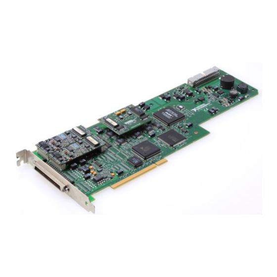
Introduction This chapter describes the NI PCI-6110/6111, lists what you need to get started, describes the optional software and optional equipment, and explains how to unpack the device. About the NI PCI-6110/6111 Thank you for buying an NI PCI-6110/6111. The NI PCI-6110/6111 is a Plug and Play, multifunction analog, digital, and timing I/O device for PCI bus computers. -
Page 12: What You Need To Get Started
Chapter 1 Introduction What You Need to Get Started To set up and use the NI PCI-6110/6111, you will need the following items: ❑ ❑ ❑ ❑ ❑ Software Programming Choices When programming the National Instruments DAQ hardware, you can use NI application development environment (ADE) software or other ADEs. -
Page 13: National Instruments Ade Software
The LabVIEW Data Acquisition VI Library, a series of virtual instruments for using LabVIEW with National Instruments DAQ hardware, is included with LabVIEW. Measurement Studio, which includes LabWindows Visual C++, and tools for Visual Basic, is a development suite that allows you to use ANSI C, Visual C++, and Visual Basic to design test and measurement software. -
Page 14: Optional Equipment
Using LabVIEW, Measurement Studio, or VI Logger greatly reduces the development time for your data acquisition and control application. Optional Equipment NI offers a variety of products to use with the NI PCI-6110/6111, including the following cables, connector blocks, and other accessories: •... -
Page 15: Unpacking
Notify NI if the device appears damaged in any way. Do not install a damaged device into the computer. Store the NI PCI-6110/6111 in the antistatic envelope when not in use. Safety Information This section contains important safety information that you must follow when installing and using the product. - Page 16 MAINS is defined as the electricity supply system to which the equipment concerned is designed to be connected either for powering the equipment or for measurement purposes. NI PCI-6110/6111 User Manual Pollution Degree 1 means no pollution or only dry, nonconductive pollution occurs.
- Page 17 Installation Category IV is for measurements performed at the source of the low-voltage (<1,000 V) installation. Examples of Installation Category IV are electric meters, and measurements on primary overcurrent protection devices and ripple-control units. Chapter 1 Introduction NI PCI-6110/6111 User Manual...
-
Page 18: Installing And Configuring The Ni Pci-6110/6111
This chapter explains how to install and configure the NI PCI-6110/6111. Installing the Software Note It is important to install the software before installing the NI PCI-6110/6111 to ensure that the device is properly detected. Installing the Hardware The following are general installation instructions. Consult the computer or chassis user manual or technical reference manual for specific instructions and warnings about installing new devices. -
Page 19: Configuring The Device
Chapter 2 Installing and Configuring the NI PCI-6110/6111 The NI PCI-6110/6111 is now installed. You are now ready to configure the device. Refer to the software documentation for configuration instructions. Configuring the Device The NI standard architecture for data acquisition and the PCI bus specification make the NI PCI-6110/6111 completely software configurable. -
Page 20: Hardware Overview
Hardware Overview This chapter presents an overview of the hardware functions on the NI PCI-6110/6111. Figures 3-1 and 3-2 show block diagrams for the NI PCI-6110 and the NI PCI-6111, respectively. CH0+ AI CH0 Amplifier CH0– – CH1+ AI CH1 Amplifier CH1–... -
Page 21: Analog Input
AI setting. Input Mode The NI PCI-6110/6111 supports only differential (DIFF) inputs. DIFF input mode provides up to four channels on the NI PCI-6110 and up to two channels on the NI PCI-6111. Note The inputs are differential only in the sense that the ground loops are broken. -
Page 22: Input Polarity And Input Range
ADC can accommodate. The NI PCI-6110/6111 has gains of 0.2, 0.5, 1, 2, 5, 10, 20, and 50, and it is suited for a wide variety of signal levels. With the proper gain setting, you can use the full resolution of the ADC to measure the input signal. -
Page 23: Considerations For Selecting Input Ranges
Figures 3-3 and 3-4. The trigger-level range for the direct analog channel is ±10 V in 78 mV steps for the NI PCI-6110/6111. The range for the post-PGIA trigger selection is simply the full-scale range of the selected channel, and the resolution is that range divided by 256. - Page 24 3-9. You can independently set lowValue and highValue in software. © National Instruments Corporation Analog Trigger Circuit Figure 3-3. Analog Trigger Block Diagram for the NI PCI-6110 Analog Trigger Circuit Figure 3-4. Analog Trigger Block Diagram for the NI PCI-6111 Chapter 3...
- Page 25 LowValue is unused. In inside-region analog triggering mode, the trigger is generated when the signal value is between the lowValue and the highValue, as shown in Figure 3-7. NI PCI-6110/6111 User Manual lowValue Trigger Figure 3-5. Below-Low-Level Analog Triggering Mode...
- Page 26 In low-hysteresis analog triggering mode, the trigger is generated when the signal value is less than lowValue, with the hysteresis specified by highValue, as shown in Figure 3-9. highValue lowValue Trigger Figure 3-9. Low-Hysteresis Analog Triggering Mode © National Instruments Corporation NI PCI-6110/6111 User Manual...
-
Page 27: Digital I/O
AI signal crosses a specific threshold. Digital I/O The NI PCI-6110/6111 contains eight lines of DIO for general-purpose use. You can individually software-configure each line for either input or output. At system startup and reset, the DIO ports are all high-impedance. - Page 28 Chapter 4, © National Instruments Corporation RTSI Trigger <0..6> PFI<0..9> Scan Interval Counter TC GPCTR0_OUT Figure 3-10. STARTSCAN Signal Routing RTSI Triggers Connecting Signals. Chapter 3 Hardware Overview STARTSCAN section, and on the PFI pins, as indicated NI PCI-6110/6111 User Manual...
-
Page 29: Programmable Function Inputs
A/D conversions, DAC updates, or general-purpose signals at the I/O connector. The NI PCI-6110/6111 can use either its internal 20 MHz timebase or a timebase received over the RTSI bus. In addition, if you configure the... -
Page 30: Rtsi Triggers
Figure 3-11. RTSI Bus Signal Connection Timing Connections section of Chapter 4, 3-11 Chapter 3 Hardware Overview DAQ-STC TRIG1 TRIG2 CONVERT* UPDATE* WFTRIG GPCTR0_SOURCE GPCTR0_GATE GPCTR0_OUT STARTSCAN AIGATE SISOURCE UISOURCE GPCTR1_SOURCE GPCTR1_GATE RTSI_OSC (20 MHz) Connecting Signals, NI PCI-6110/6111 User Manual... -
Page 31: Connecting Signals
Connections that exceed any of the maximum ratings of input or output signals on the NI PCI-6110/6111 can damage the device and the computer. Maximum input ratings for each signal are given in the Protection column of Table 4-3. NI is not liable for any damage resulting from such signal connections. - Page 32 DGND +5 V DGND PFI5/UPDATE* PFI6/WFTRIG DGND PFI9/GPCTR0_GATE GPCTR0_OUT FREQ_OUT NC on NI PCI-6111 NC = No Connect Figure 4-1. 68-Pin I/O Connector Pin Assignment for the NI PCI-6110/6111 ACH0+ ACH0GND ACH1– ACH2+ ACH2GND ACH3– AOGND AOGND DGND DIO0 DIO5...
-
Page 33: I/O Connector Signal Descriptions
ACH1+ ACH0– ACH0+ ACH<0..3>GND ACH<0..3>GND NC on NI PCI-6111 Figure 4-2. 50-Pin Connector Pin Assignments for the NI PCI-6110/6111 Direction — — Analog Input Channels 0 through 3 ground—These pins are the bias current return point for differential measurements. ACH<2..3>GND signals are no connects on the NI PCI-6111. - Page 34 EXTSTROBE* DGND PFI0/TRIG1 DGND PFI1/TRIG2 DGND NI PCI-6110/6111 User Manual Direction Input Analog Input Channels 0 through 3 (–)—These pins are routed to the (–) terminal of the respective channel amplifier. ACH<2..3>– signals are no connects on the NI PCI-6111.
- Page 35 Input PFI9/Counter 0 Gate—As an input, this is a PFI. Output As an output, this is the GPCTR0_GATE signal. This signal reflects the actual gate signal connected to the general-purpose counter 0. Chapter 4 Connecting Signals NI PCI-6110/6111 User Manual...
- Page 36 Chapter 4 Connecting Signals Table 4-2. Signal Descriptions for I/O Connector Pins (Continued) Signal Name Reference GPCTR0_OUT DGND FREQ_OUT DGND Table 4-3. I/O Signal Summary for the NI PCI-6110/6111 Signal Type and Signal Name Direction ACH<0..3>+ ACH<0..3>– ACH<0..3>GND DAC0OUT DAC1OUT...
- Page 37 Table 4-3. I/O Signal Summary for the NI PCI-6110/6111 (Continued) Signal Type and Signal Name Direction PFI3/GPCTR1_SOURCE PFI4/GPCTR1_GATE GPCTR1_OUT PFI5/UPDATE* PFI6/WFTRIG PFI7/STARTSCAN PFI8/GPCTR0_SOURCE PFI9/GPCTR0_GATE GPCTR0_OUT FREQ_OUT Applies to gain 1, impedance refers to ACH<0..3>– Applies to gain > 1, impedance refers to ACH<0..3>–...
-
Page 38: Connecting Analog Input Signals
Chapter 4 Connecting Signals Connecting Analog Input Signals The NI PCI-6110/6111 channels are configured as pseudodifferential inputs. The input signal of each channel, ACH<0..3>+, is tied to the positive input of the PGIA, and each reference signal ACH<0..3>–, is tied to the negative input of the PGIA. -
Page 39: Types Of Signal Sources
The PGIA applies gain and common-mode voltage rejection and presents high input impedance to the AI signals connected to the NI PCI-6110/6111. Signals are routed to the positive and negative inputs of the PGIA. The PGIA converts two input signals to a signal that is the difference between the two input signals multiplied by the gain setting of the amplifier. -
Page 40: Differential Measurements
See text for information on bias resistors. Differential Connection Considerations A differential connection is one in which the NI PCI-6110/6111 AI signal has its own reference signal or signal return path. The device channels are always configured in DIFF input mode. The input signal is tied to the positive input of the PGIA, and its reference signal, or return, is tied to the negative input of the PGIA. -
Page 41: Differential Connections For Ground-Referenced Signal Sources
Differential Connections for Ground-Referenced Signal Sources Figure 4-4 shows how to connect a ground-referenced signal source to a channel on the NI PCI-6110/6111. Ground- Referenced Signal Source – Common- Mode Noise and Ground – Potential I/O Connector With this type of connection, the PGIA rejects both the common-mode... -
Page 42: Differential Connections For Nonreferenced Or Floating Signal Sources
Common-Mode Signal Rejection Considerations Figure 4-4 shows connections for signal sources that are already referenced to some ground point with respect to the NI PCI-6110/6111. In theory, the PGIA can reject any voltage caused by ground-potential differences between the signal source and the device. In addition, with pseudodifferential input connections, the PGIA can reject common-mode noise pickup in the leads connecting the signal sources to the device. -
Page 43: Working Voltage Range
Like any amplifier, the common-mode rejection ratio (CMRR) of the PGIA is limited at high frequency. This limitation has been compensated for in the design of the NI PCI-6110/6111 by using a common-mode choke on each channel. The purpose of the 10 nF capacitance on the ACH<0..3>–... -
Page 44: Analog Output Signal Connections
DAC0OUT is the voltage output signal for AO channel 0, DAC1OUT is the voltage output signal for AO channel 1, and AOGND is the ground reference signal for the AO channels. Figure 4-6 shows how to make AO connections to the NI PCI-6110/6111. Load VOUT 0... -
Page 45: Digital I/O Signal Connections
Caution Exceeding the maximum input voltage ratings, which are listed in Table 4-3, can damage the NI PCI-6110/6111 and the computer. NI is not liable for any damage resulting from such signal connections. Figure 4-7 shows signal connections for three typical DIO applications. -
Page 46: Power Connections
Under no circumstances should you connect these +5 V power pins directly to analog or digital ground or to any other voltage source on the NI PCI-6110/6111 or any other device. Doing so can damage the device and the computer. NI is not liable for damage resulting from such a connection. -
Page 47: Programmable Function Input Connections
All digital timing connections are referenced to DGND. Figure 4-8 illustrates how to connect an external TRIG1 source and an external CONVERT* source to two NI PCI-6110/6111 PFI pins. TRIG1 STARTSCAN Source Programmable Function Input Connections There are a total of 13 internal timing signals that you can externally control from the PFI pins. -
Page 48: Daq Timing Connections
Posttriggered data acquisition allows you to view only data that is acquired after a trigger event is received. A typical posttriggered DAQ sequence is shown in Figure 4-9. On the NI PCI-6110/6111, each STARTSCAN pulse initiates one CONVERT* pulse. STARTSCAN... -
Page 49: Trig1 Signal
The selected edge of the TRIG1 starts the DAQ sequence for both posttriggered and pretriggered acquisitions. The NI PCI-6110/6111 supports analog triggering on the PFI0/TRIG1 pin. Refer to Chapter 3, information on analog triggering. -
Page 50: Trig2 Signal
After the SC decrements to zero, it is loaded with the number of posttrigger scans to acquire while the acquisition continues. The device ignores TRIG2 if it is asserted prior to the SC decrementing to zero. After NI PCI-6110/6111 User Manual Polarity Polarity Figure 4-11. - Page 51 Figures 4-13 and 4-14 show the timing requirements for TRIG2. Rising-Edge Falling-Edge © National Instruments Corporation Polarity Polarity Figure 4-13. TRIG2 Input Signal Timing = 25 to 50 ns Figure 4-14. TRIG2 Output Signal Timing 4-21 Chapter 4 Connecting Signals = 10 ns minimum NI PCI-6110/6111 User Manual...
-
Page 52: Startscan Signal
This output is set to high-impedance at startup. Figures 4-15 and 4-16 show the input and output timing requirements for STARTSCAN. Rising-Edge Falling-Edge NI PCI-6110/6111 User Manual Polarity Polarity Figure 4-15. STARTSCAN Input Signal Timing 4-22 after the = 10 ns minimum ni.com... - Page 53 DAQ sequence may be gated by either the hardware (AIGATE) signal or software command register gate. The NI PCI-6110/6111 uses a three-point analog FIFO to digitize the input. Although the point is digitized on the appropriate edge of STARTSCAN (internally supplied unless you pass 0 for the scanTimebase), it is not sent to NI-DAQ until three additional edges of STARTSCAN clock the point.
-
Page 54: Convert* Signal
The output is an active low pulse with a pulse width of 50 to 100 ns. This output is set to high-impedance at startup. Figures 4-17 and 4-18 show the timing requirements for CONVERT*. Rising-Edge Falling-Edge NI PCI-6110/6111 User Manual Polarity Polarity Figure 4-17. CONVERT* Input Signal Timing 4-24 = 10 ns minimum ni.com... -
Page 55: Aigate Signal
The SI2 on the NI PCI-6110/6111 normally generates CONVERT* unless you select some external source. The counter is started by the STARTSCAN signal and continues to count down and reload itself until the scan is finished. -
Page 56: Sisource Signal
This signal has a 450 ns pulse width and is software enabled. SCANCLK polarity is low-to-high and cannot be changed programmatically using Note NI-DAQ. NI PCI-6110/6111 User Manual = 50 ns minimum = 23 ns minimum Figure 4-19. SISOURCE Signal Timing 4-26 ni.com... -
Page 57: Extstrobe* Signal
EXTSTROBE* cannot be enabled through NI-DAQ. Figure 4-21 shows the timing for the hardware-strobe mode EXTSTROBE* signal. Waveform Generation Timing Connections The analog group defined for the NI PCI-6110/6111 is controlled by WFTRIG, UPDATE*, and UISOURCE. © National Instruments Corporation CONVERT*... -
Page 58: Wftrig Signal
25 to 50 ns. This output is set to high-impedance at startup. Figures 4-22 and 4-23 show the timing requirements for WFTRIG. Rising-Edge Falling-Edge NI PCI-6110/6111 User Manual Polarity Polarity Figure 4-22. WFTRIG Input Signal Timing = 25 to 50 ns Figure 4-23. -
Page 59: Update* Signal
UPDATE* pulses with enough time that new data can be written to the DAC latches. © National Instruments Corporation Polarity Polarity Figure 4-24. UPDATE* Input Signal Timing = 50 to 75 ns Figure 4-25. UPDATE* Output Signal Timing 4-29 Chapter 4 Connecting Signals = 10 ns minimum NI PCI-6110/6111 User Manual... -
Page 60: Uisource Signal
Chapter 4 Connecting Signals The NI PCI-6110/6111UI normally generates UPDATE* unless you select some external source. The WFTRIG signal starts the UI, and the UI can be stopped by software or the internal Buffer Counter. D/A conversions generated by either an internal or external UPDATE* signal do not occur when gated by the software command register gate. -
Page 61: Gpctr0_Source Signal
© National Instruments Corporation = 50 ns minimum = 10 ns minimum Figure 4-27. GPCTR0_SOURCE Signal Timing 4-31 Chapter 4 Connecting Signals NI PCI-6110/6111 User Manual... -
Page 62: Gpctr0_Out Signal
Figure 4-29 shows the timing of GPCTR0_OUT. GPCTR0_SOURCE GPCTR0_OUT (Pulse on TC) GPCTR0_OUT (Toggle Output on TC) NI PCI-6110/6111 User Manual Polarity Polarity Figure 4-28. GPCTR0_GATE Signal Timing Figure 4-29. GPCTR0_OUT Signal Timing 4-32 = 10 ns minimum... -
Page 63: Gpctr0_Up_Down Signal
The 20 MHz or 100 kHz timebase normally generates the GPCTR1_SOURCE unless you select some external source. © National Instruments Corporation = 50 ns minimum = 10 ns minimum Figure 4-30. GPCTR1_SOURCE Signal Timing 4-33 Chapter 4 Connecting Signals NI PCI-6110/6111 User Manual... -
Page 64: Gpctr1_Gate Signal
1, even if the gate is being externally generated by another PFI. This output is set to high-impedance at startup. Figure 4-31 shows the timing requirements for the GPCTR1_GATE signal. Rising-Edge Falling-Edge NI PCI-6110/6111 User Manual Polarity Polarity Figure 4-31. GPCTR1_GATE Signal Timing 4-34 = 10 ns minimum ni.com... - Page 65 DIO7 pin free for general use. Figure 4-33 shows the timing requirements for the GATE and SOURCE input signals and the timing specifications for the NI PCI-6110/6111 OUT output signals. © National Instruments Corporation Chapter 4 Figure 4-32.
- Page 66 The GATE input timing parameters are referenced to the signal at the SOURCE input or to one of the internally generated signals on the NI PCI-6110/6111. Figure 4-33 shows the GATE signal referenced to the rising edge of a source signal. The gate must be valid (either high or low)
-
Page 67: Freq_Out Signal
Field Wiring Considerations Environmental noise can seriously affect the measurement accuracy of the NI PCI-6110/6111 if you do not take proper care when running signal wires between signal sources and the device. The following recommendations apply mainly to AI signal routing to the device, although they also apply to signal routing in general. - Page 68 For more information, refer to the NI Developer Zone tutorial, Field Wiring and Noise Consideration for Analog Signals, available at NI PCI-6110/6111 User Manual separate them by a reasonable distance if they run in parallel, or run the lines at right angles to each other.
-
Page 69: Calibration
Calibration refers to the process of minimizing measurement and output voltage errors by making small circuit adjustments. On the NI PCI-6110/6111, these adjustments take the form of writing values to onboard calibration DACs (CalDACs). Most applications require some form of device calibration. If you do not calibrate the device, the signals and measurements could have very large offset, gain, and linearity errors. -
Page 70: Self-Calibration
It is better to self-calibrate when the device is installed in the environment in which it is used. Self-Calibration The NI PCI-6110/6111 can measure and correct for almost all of its calibration-related errors without any external signal connections. NI-DAQ provides a self-calibration method. This self-calibration process, which generally takes less than a minute, is the preferred method of assuring accuracy in your application. - Page 71 Specifications This appendix lists the specifications of the NI PCI-6110/6111. These specifications are typical at 25 °C unless otherwise noted. Analog Input Input Characteristics Number of channels Type of ADC Sampling rate Input coupling ... DC or AC Max working voltage for all AI channels Input Channels ACH<0..3>+...
- Page 72 Appendix A Specifications FIFO buffer size...8,192 samples Data transfers ...DMA, interrupts, DMA modes ...Scatter-gather (single transfer, Accuracy Information Table A-1. NI PCI-6110/6111 Accuracy Information Nominal Range % of Reading Full Scale 24 Hours 90 Days ±42 0.51 0.51 ±20 0.51 0.51...
- Page 73 Overload ... 1 M Impedance to ground ACH<0..3>– to ground... 10 nF Range 200 mV 500 mV to 50 V Appendix A Specifications = 100 kHz input range = ±10 V Small Signal (–3 dB) 4 MHz 5 MHz NI PCI-6110/6111 User Manual...
- Page 74 DC to 60 Hz , not including quantization Stability Recommended warm-up time...15 minutes Offset temperature coefficient Gain temperature coefficient ...±20 ppm/°C Onboard calibration reference NI PCI-6110/6111 User Manual Table A-2. Analog Input Characteristics SFDR Typ SFDR Max (dB) (dB) Pregain...±5 V/°C Postgain ...±50 V/°C...
- Page 75 DMA modes ... Scatter gather (single transfer, Transfer Characteristics Relative accuracy (INL)... ±4 LSB typ, ±8 LSB max DNL ... ±2 LSB typ, ±8 LSB max Table A-3. NI PCI-6110/6111 Analog Output DC Accuracy Information % of Reading Nominal Range (V) 24 Hrs ±10...
- Page 76 Offset temperature coefficient ...±500 V/°C Gain temperature coefficient Onboard calibration reference Digital I/O Number of channels...8 input/output Compatibility ...TTL/CMOS NI PCI-6110/6111 User Manual Settling Time for Full-Scale Step 300 ns to ±0.01% Internal reference...±50 ppm/°C External reference...±25 ppm/°C Level ...5.000 V (±2.5 mV) Temperature coefficient...±2.0 ppm/°C max...
- Page 77 Minimum = 0 V) — = 5 V) — — 4.35 V Appendix A Specifications 0.8 V 5.0 V — –320 A — 10 A — 0.4 V — Maximum 0.8 V –320 0.4 V — NI PCI-6110/6111 User Manual...
- Page 78 Base clock accuracy...±0.01% Data transfers ...DMA, interrupts, Triggers Analog Trigger Number of triggers...1 Purpose NI PCI-6110/6111 User Manual Level = 5 mA) = 3.5 mA) Analog input ...Start and stop trigger, gate, clock Analog output ...Start trigger, gate, clock General-purpose counter/timers ...Source, gate...
- Page 79 Internal source, ACH<0..3>... 5 MHz External source, PFI0/TRIG1 ... 5 MHz Analog input ... Start and stop trigger, gate, clock Analog output ... Start trigger, gate, clock General-purpose counter/timers... Source, gate Appendix A Specifications external trigger (PFI0/TRIG1) (software-selectable) (software-selectable) NI PCI-6110/6111 User Manual...
-
Page 80: Bus Interface
Maximum working voltage refers to the signal voltage plus the common-mode voltage. Channel-to-earth ...42 V, Installation Category I Channel-to-channel...42 V, Installation Category I NI PCI-6110/6111 User Manual Digital trigger ...–0.5 V to (V Analog trigger On/disabled...±35 V Powered off ...±35 V NI PCI-6110 ...2.5 A... -
Page 81: Electromagnetic Compatibility
For EMC compliance, you must operate this device with shielded cabling. © National Instruments Corporation IEC 61010-1, EN 61010-1 UL 3111-1, UL 61010B-1 CAN/CSA C22.2 No. 1010.1 A-11 Appendix A Specifications ni.com FCC Part 15A above 1 GHz Table 1 (Class A) Compliant NI PCI-6110/6111 User Manual... - Page 82 Select the appropriate product family, followed by your product, and a link to the DoC appears in Adobe Acrobat format. Click the Acrobat icon to download or read the DoC. NI PCI-6110/6111 User Manual . This Web site lists the DoCs by ni.com/hardref.nsf/ A-12 ni.com...
- Page 83 Figure B-1 shows the pin assignments for the 68-pin NI PCI-6110/6111 connector. This connector is available when you use the SH6868EP cable assemblies with the NI PCI-6110/6111. Figure B-2 shows the pin assignments for the NI PCI-6110/6111 when used with 50-pin accessories. © National Instruments Corporation...
- Page 84 11 45 PFI1/TRIG2 10 44 DGND +5 V DGND PFI5/UPDATE* PFI6/WFTRIG DGND PFI9/GPCTR0_GATE GPCTR0_OUT FREQ_OUT NC on NI PCI-6111 Figure B-1. 68-Pin Connector Pin Assignment for the NI PCI-6110/6111 ACH0+ ACH0GND ACH1– ACH2+ ACH2GND ACH3– AOGND AOGND DGND DIO0 DIO5 DGND...
- Page 85 ACH3– 10 35 ACH3+ ACH2– ACH2+ ACH1– ACH1+ ACH0– ACH0+ ACH<0..3>GND ACH<0..3>GND NC on NI PCI-6111 Figure B-2. 50-Pin Connector Pin Assignment for the NI PCI-6110/6111 Appendix B Cable Connector Descriptions FREQ_OUT GPCTR0_OUT PFI9/GPCTR0_GATE PFI8/GPCTR0_SOURCE PFI7/STARTSCAN PFI6/WFTRIG PFI5/UPDATE* GPCTR1_OUT PFI4/GPCTR1_GATE...
-
Page 86: General Information
Sampling rate is the fastest you can acquire data on the device and still achieve accurate results. The NI PCI-6110/6111 has a sampling rate of 5 MS/s. This sampling rate is at 5 MS/s regardless if 1 or 4 channels are acquiring data. - Page 87 The NI-DAQ User Manual for PC Compatibles describes the general programming flow and provides example code for using the NI-DAQ API. For a list of functions that support the NI PCI-6110/6111, you can refer to the NI-DAQ Function Reference Help (for NI-DAQ version 6.7 or later) or the NI-DAQ Function Reference Manual (for NI-DAQ version 6.6 or...
- Page 88 Analog Input and Output Why is there a minimum sampling rate on the NI PCI-6110/6111? The NI PCI-6110/6111 makes use of a pipelined ADC in order to achieve its high sampling rates. Sampling at rates below 20 kS/s can result in improper digitalization, which would appear as noise in the acquired data.
- Page 89 The DAQ-STC-based MIO devices have a 20 MHz timebase. The Am9513-based MIO devices have a 1 MHz or 5 MHz timebase. NI PCI-6110/6111 User Manual Set up acquisition timing so that the timing signal for A/D conversion comes from PFI5, as follows: •...
- Page 90 If you are using NI-DAQ with LabVIEW, some applications that were built using the CTR VIs still run. However, there are many differences between the counters of the NI PCI-6110/6111 and those of other devices: the counter numbers are different, timebase selections are different, and the DAQ-STC counters are 24-bit counters (unlike the 16-bit counters on devices without the DAQ-STC).
- Page 91 DIO(0) is in the high impedance state after power-on, and Table 4-3 shows that there is a 50 k pull-up resistor. This pull-up resistor sets the DIO(0) pin to a logic high when the output is in a high-impedance state. NI PCI-6110/6111 User Manual Table C-1. Signal Name Equivalencies LabVIEW Route Signal —...
- Page 92 Technical Support and Professional Services Visit the following sections of the National Instruments Web site at ni.com • • • • © National Instruments Corporation for technical support and professional services: Support—Online technical support resources include the following: – Self-Help Resources—For immediate answers and solutions,...
- Page 93 You also can visit the Worldwide Offices section of office Web sites, which provide up-to-date contact information, support phone numbers, email addresses, and current events. NI PCI-6110/6111 User Manual and could not find the answers you need, contact ni.com ni.com/niglobal to access the branch ni.com...
- Page 94 Value –12 –9 – 6 –3 kilo tera degrees greater than greater than or equal to less than less than or equal to percent plus or minus positive of, or plus negative of, or minus ohms NI PCI-6110/6111 User Manual...
- Page 95 +5 V ACH0GND AIGATE AIGND ANSI AOGND ASIC bipolar NI PCI-6110/6111 User Manual square root of +5 VDC source signal amperes analog-to-digital alternating current analog input channel signal analog input channel ground signal analog-to-digital converter—an electronic device, often an integrated...
- Page 96 (timing) counter Glossary NI PCI-6110/6111 User Manual...
- Page 97 DAC0OUT DAC1OUT DAQ-STC DGND DIFF dithering NI PCI-6110/6111 User Manual digital-to-analog digital-to-analog converter—an electronic device, often an integrated circuit, that converts a digital number into a corresponding analog voltage or current analog channel 0 voltage output signal analog channel 1 voltage output signal data acquisition—a system that uses the computer to collect, receive,...
- Page 98 A/D converter (in dB) minus 1.76, divided by 6.02. Also called effective bits. electrostatic discharge—a high-voltage, low-current discharge of static electricity that can damage sensitive electronic components. Electrostatic discharge voltage can easily range from 1,000 to 10,000 V. external strobe signal farads Federal Communications Commission Glossary NI PCI-6110/6111 User Manual...
- Page 99 GPCTR1_GATE GPCTR1_OUT GPCTR1_SOURCE NI PCI-6110/6111 User Manual first-in first-out memory buffer—FIFOs are often used on DAQ devices to temporarily store incoming or outgoing data until that data can be read or written. For example, an analog input FIFO stores the results of A/D conversions until the data can be read into system memory.
- Page 100 The interchannel delay is regulated by CONVERT*. input/output—the transfer of data to/from a computer system involving communications channels, operator interface devices, and/or data acquisition and control interfaces current, output high current, output low current out interrupt request Glossary NI PCI-6110/6111 User Manual...
- Page 101 R = response, S = stimulus, and K = a constant least significant bit meter megabytes of memory a controlled centralized configuration environment that allows you to configure all of your National Instruments DAQ, GPIB, IMAQ, IVI, Motion, VISA, and VXI devices megahertz multifunction I/O MXI Interface to Everything most significant bit ni.com...
- Page 102 National Instruments National Instruments driver software for DAQ hardware an undesirable electrical signal—Noise comes from external sources such as the AC power line, motors, generators, transformers, fluorescent lights, CRT displays, computers, electrical storms, welders, radio transmitters, and internal sources such as semiconductors, resistors, and capacitors.
- Page 103 PFI9/GPCTR0_GATE PGIA Plug and Play devices port posttriggering potentiometer precision pretriggering pseudodifferential input NI PCI-6110/6111 User Manual PFI2/convert PFI3/general-purpose counter 1 source PFI4/general-purpose counter 1 gate PFI5/update PFI6/waveform trigger PFI7/start of scan PFI8/general-purpose counter 0 source PFI9/general-purpose counter 0 gate...
- Page 104 National Instruments timing bus that connects DAQ devices directly, by means of connectors on top of the devices, for precise timing synchronization between multiple devices RTSI Oscillator—RTSI bus master clock...
- Page 105 SISOURCE SOURCE STARTSCAN system noise NI PCI-6110/6111 User Manual reciprocal of the scan interval scan clock signal small computer system interface—a high-speed, peripheral-connect interface primarily used for hard disks, CD-ROM drives, tape drives, and other mass-storage devices to PCs...
- Page 106 PC, that has the functionality of a classic stand-alone instrument (2) a LabVIEW software module (VI), which consists of a front panel user interface and a block diagram program G-13 Glossary NI PCI-6110/6111 User Manual...
- Page 107 Glossary WFTRIG NI PCI-6110/6111 User Manual volts, input high volts, input low volts in measured voltage volts, output high volts, output low reference voltage volts, root mean square ground-referenced signal source waveform generation trigger signal G-14 ni.com...
- Page 108 A-3 analog input input coupling, 3-4 input mode, 3-2 input polarity and input range, 3-3 questions about, C-3 signal connections, 4-8 specifications amplifier characteristics, A-3 dynamic characteristics, A-3 input characteristics, A-1 stability, A-4 transfer characteristics, A-2 NI PCI-6110/6111 User Manual...
- Page 109 (note), 3-4 below-low-level analog triggering mode, 3-6 bipolar input, 3-3 block diagrams NI PCI-6110, 3-1 analog trigger, 3-5 NI PCI-6110/6111 User Manual NI PCI-6111, 3-2 analog trigger, 3-5 interface specifications, A-10 overview, 1-1 PCI Local Bus Specification Revision 2.0, 2-2...
- Page 110 3-8 specifications, A-9 DIO<0..7> signal description (table), 4-4 digital I/O connections, 4-15 signal summary (table), 4-6 documentation conventions used in the manual, ix National Instruments documentation, x online library, D-1 related documentation, xi NI PCI-6110/6111 User Manual Index...
- Page 111 (table), 4-6 general-purpose timing connections, 4-37 signal summary (table), 4-7 frequently asked questions. See questions and answers fuse, self-resetting, 4-16, C-2 NI PCI-6110/6111 User Manual general-purpose timing signal connections FREQ_OUT signal, 4-37 GPCTR0_GATE signal, 4-31 GPCTR0_OUT signal, 4-32 GPCTR0_SOURCE signal, 4-31...
- Page 112 D-1 technical support, D-1 high-hysteresis analog triggering mode, 3-7 highValue, 3-5, 3-6, 3-7 I/O connectors cable options for the NI PCI-6110/6111, connector details (table), 4-1 exceeding maximum ratings (caution), 4-1 pin assignments 50-pin connector (figure), 4-3, B-3...
- Page 113 NI PCI-6110, 3-1 NI PCI-6111, 3-2 custom cabling, 1-4 optional equipment, 1-4 overview, 1-1 NI PCI-6110/6111 User Manual questions about analog input and output, C-3 general information, C-1 installing and configuring, C-2 timing and digital I/O, C-4 requirements for getting started, 1-2...
- Page 114 (PFIs). See PFIs (programmable function inputs) programmable gain instrumentation amplifier. See PGIA programming examples, D-1 questions and answers analog input and output, C-3 general information, C-1 installing and configuring, C-2 timing and digital I/O, C-4 NI PCI-6110/6111 User Manual Index...
- Page 115 4-10 floating signal sources, 4-12 ground-referenced signal sources, 4-11 overview, 4-10 recommended configuration (table), 4-10 NI PCI-6110/6111 User Manual digital I/O, 4-15 field wiring considerations, 4-37 I/O connector connector details (table), 4-1 exceeding maximum ratings (caution), 4-1 pin assignments...
- Page 116 (figure), 4-19 using the SISOURCE signal, 4-26 support, technical, D-1 system integration services, D-1 technical support, D-1 telephone technical support, D-2 timing connections DAQ timing connections AIGATE signal, 4-25 CONVERT* signal, 4-24 NI PCI-6110/6111 User Manual Index...
- Page 117 See digital trigger troubleshooting resources, D-1 UISOURCE signal timing connections, 4-30 timing diagram, 4-30 unpacking the NI PCI-6110/6111, 1-5 UPDATE* signal See also PFI5/UPDATE* signal timing connections, 4-29 using with UISOURCE signal, 4-30 using with WFTRIG signal, 4-28...
- Page 118 D-1 technical support, D-1 © National Instruments Corporation WFTRIG signal See also PFI6/WFTRIG signal timing connections, 4-28 using with UPDATE* signal, 4-30 wiring considerations, 4-37 working voltage range, 4-13 worldwide technical support, D-2 I-11 NI PCI-6110/6111 User Manual Index...