Table of Contents
Advertisement
Quick Links
Advertisement
Table of Contents

Related Manuals for National Instruments NI PXI-1056


Summary of Contents for National Instruments NI PXI-1056
- Page 1 NI PXI-1056 User Manual NI PXI-1056 User Manual September 2005 371551A-01...
- Page 2 For further support information, refer to the Technical Support and Professional Services appendix. To comment on National Instruments documentation, refer to the National Instruments Web site at ni.com/info and enter the info code feedback. © 2005 National Instruments Corporation. All rights reserved.
-
Page 3: Important Information
Warranty The NI PXI-1056 is warranted against defects in materials and workmanship for a period of one year from the date of shipment, as evidenced by receipts or other documentation. National Instruments will, at its option, repair or replace equipment that proves to be defective during the warranty period. -
Page 4: Table Of Contents
Setting Fan Speed ...2-3 Installing Filler Panels...2-3 Rack Mounting ...2-4 Connecting Safety Ground...2-4 Connecting to Power Source...2-4 Installing a PXI Controller...2-5 Installing PXI Modules ...2-7 Power Switch LED Indicator ...2-8 Front Panel LED Indicators ...2-8 © National Instruments Corporation NI PXI-1056 User Manual... - Page 5 Replacing the Modular Power Supply... 3-3 Removal ... 3-4 Installation... 3-4 Configuration ... 3-4 Connecting Safety Ground... 3-4 Connecting to Power Source... 3-4 Appendix A Specifications Appendix B Pinouts Appendix C Technical Support and Professional Services Glossary Index NI PXI-1056 User Manual ni.com...
-
Page 6: About This Manual
About This Manual configuring, using, and maintaining the NI PXI-1056 18-slot chassis. Conventions The following conventions are used in this manual: » The » symbol leads you through nested menu items and dialog box options to a final action. The sequence File»Page Setup»Options directs you to pull down the File menu, select the Page Setup item, and select Options from the last dialog box. -
Page 7: Related Documentation
• • • • • NI PXI-1056 User Manual CompactPCI Specification PICMG 2.0 R 3.0 PXI Hardware Specification, Revision 2.2 PXI Software Specification, Revision 2.2 IEEE 1101.1-1991, IEEE Standard for Mechanical Core Specifications for Microcomputers Using IEC 603-2 Connectors IEEE 1101.10, IEEE Standard for Additional Mechanical... -
Page 8: Getting Started
© National Instruments Corporation PXI-1056 chassis Filler panels AC power cable (refer to Table 1-1 for AC power cables) NI PXI-1056 User Manual Read Me First: Safety and Radio-Frequency Interference Driver CD-ROM containing NI PXI chassis software Chassis number labels... -
Page 9: Key Features
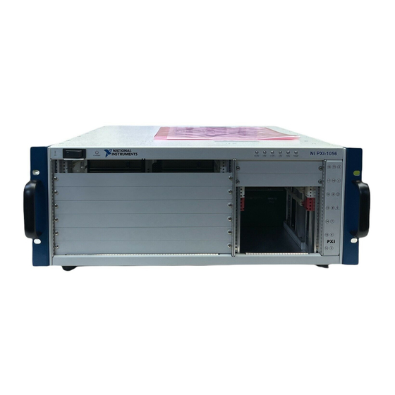
United Kingdom 230 V If you are missing any of the items listed in Table 1-1, or if you have the incorrect AC power cable, contact National Instruments. Key Features The PXI-1056 combines a high-performance 18 slot 3U-sized (or 4 3U and... -
Page 10: Chassis Description
6 6U Filler Panels 7 Rubber Feet 8 Controller Expansion Slots Figure 1-1. Front View of the PXI-1056 Chassis Chapter 1 Getting Started NI PXI-1056 9 System Controller Slot 10 Star Trigger/Peripheral Slot 11 Voltage/Fan/Temperature LEDs NI PXI-1056 User Manual... -
Page 11: Optional Equipment
3 Power Supply Shuttle Handles (x2) 4 Chassis Ground Screw 5 Circuit Breaker Optional Equipment Contact National Instruments to order the following options for the PXI-1056 chassis. EMC Filler Panels Optional EMC filler panel kits are available from National Instruments. -
Page 12: Pxi-1056 Backplane Overview
ST functionality that can provide individual triggers to all other peripheral modules. However, if you do not require advanced trigger functionality, you can install any standard peripheral module in this slot. © National Instruments Corporation Chapter 1 Getting Started NI PXI-1056 User Manual... -
Page 13: Peripheral Slots
TTL side-band digital communication path that does not reduce the PXI bus bandwidth. Initialization software uses the configuration information specific to adjacent peripheral modules to evaluate local bus compatibility. NI PXI-1056 User Manual section. ni.com... - Page 14 Chapter 1 Getting Started Controller Trigger Star Controller System Figure 1-3. PXI CLK_10 and Star Trigger Routing © National Instruments Corporation NI PXI-1056 User Manual...
-
Page 15: Trigger Bus
Measurement & Automation Explorer (MAX). Dynamic routing of triggers (automatic line assignments) is supported through certain National Instruments drivers like NI-DAQmx. Although any trigger line may be routed in either direction, it cannot be routed in Note more than one direction at a time. -
Page 16: Installation And Configuration
Part Replacement—Only service this equipment with parts that are exact replacements, both electrically and mechanically. Contact National Instruments for replacement part information. Installation of parts with those that are not direct replacements may cause harm to Connecting Safety Ground... -
Page 17: Chassis Cooling Considerations
When rack mounting the PXI-1056, provide at least 44.5 mm (1.75 in.) clearance on the right side of the unit for adequate venting. High-power applications may require additional clearance. NI PXI-1056 User Manual personnel operating the chassis. Furthermore, damage or fire may occur if replacement parts are unsuitable. -
Page 18: Setting Fan Speed
Secure with the captive mounting screws provided. © National Instruments Corporation Chapter 2 2 Air Intake (Back of Chassis) Figure 2-1. PXI-1056 Chassis Airflow Side View Rear View of the PXI-1056 Chassis, to locate the fan-speed Installation and Configuration NI PXI-1056 User Manual... -
Page 19: Rack Mounting
Chapter 2 Installation and Configuration Rack Mounting Rack-mount applications may require the optional rear rack mount kit available from National Instruments. Refer to Figure A-3, Mount to install your PXI-1056 in an instrument rack. Note You may want to remove the feet from the PXI-1056 when rack mounting. To do so, remove the screws holding the feet in place. -
Page 20: Installing A Pxi Controller
(right and left). Slide the controller to the rear of the chassis (making sure that the injector/ejector handle is pushed down as shown in Figure 2-2). Chapter 2 Installation and Configuration NI PXI-1056 User Manual... - Page 21 Figure 2-3 shows a PXI controller installed in the system controller slot of a PXI-1056 chassis. You can place CompactPCI or PXI modules in any other slot. NI PXI-1056 User Manual Figure 2-2. Injector/Ejector Handle Position during Controller or Peripheral Module Insertion When you begin to feel resistance, push up on the injector/ejector handle to inject the controller fully into the chassis frame.
-
Page 22: Installing Pxi Modules
When you begin to feel resistance, push up on the injector/ejector handle to fully inject the module into the chassis frame. Secure the module front panel to the chassis using the module front-panel mounting screws. Chapter 2 Installation and Configuration 3 NI PXI Controller NI PXI-1056 User Manual... -
Page 23: Power Switch Led Indicator
Power supply output voltages out of regulation may result in equipment malfunction, incorrect data, or failure of system to boot. NI PXI-1056 User Manual 3 Injector/Ejector Handle Figure 2-4. Installing PXI or CompactPCI Modules 4 NI PXI Controller ni.com... -
Page 24: Remote Voltage, Temperature, And Fan Monitoring
© National Instruments Corporation Chapter 2 Table 2-1. Voltage Monitoring Connector Pinout D-sub Pin Installation and Configuration Signal Ground Receive data input Request to send, input Transmit data, output Clear to send, output Reserved Reserved Reserved Reserved NI PXI-1056 User Manual... -
Page 25: Serial Communication Command Set
The commands are case sensitive. Notes The order of the <CR><LF> commands is the ideal order, and may not be implemented as such in older versions of the SMM code. NI PXI-1056 User Manual Parameter 9600 None None 2-10 Value ni.com... - Page 26 Temperature sensor #2, x = OK or FAIL Temperature sensor #3, x = OK or FAIL Description Transmit all fan speeds Transmit fan speed #1 value Transmit fan speed #2 value Transmit fan speed #3 value Transmit fan speed #4 value 2-11 NI PXI-1056 User Manual...
- Page 27 SV:V2: x<CR><LF> SV:V3: x<CR><LF> SV:V4: x<CR><LF> SV:V5: x<CR><LF> NI PXI-1056 User Manual Fan #1, x = OK or FAIL Fan #2, x = OK or FAIL Fan #3, x = OK or FAIL Fan #4, x = OK or FAIL Transmit all voltages as listed below: Voltage of the +3.3VDC Power supply...
- Page 28 +5VDC VSB supply, x = OK or FAIL Fan #1, x = OK or FAIL Fan #2, x = OK or FAIL Fan #3, x = OK or FAIL Fan #4, x = OK or FAIL 2-13 Installation and Configuration Description NI PXI-1056 User Manual...
-
Page 29: Pxi System Configuration With Max
PXI system. After installing the software on the NI Driver CD-ROM, the MAX icon will be present on the desktop. The configuration steps for single- or multiple-chassis systems are the same. NI PXI-1056 User Manual Response –V1 = +3.3 VDC –V2 = +5 VDC –V3 = +12 VDC... -
Page 30: Basic Pxi System Configuration
PXI System branch will show all of the devices in the system that can be recognized by NI-VISA. Once your controller and all of your chassis have been identified, the required will be complete. 2-15 Chapter 2 Installation and Configuration pxisys.ini NI PXI-1056 User Manual file... -
Page 31: Trigger Configuration In Max
“pre-allocates” a trigger line to prevent its configuration by a user program. Dynamic reservation/routing/deallocation is “on the fly” within a user program based upon National Instruments APIs such as NI-DAQmx. Static reservation of trigger lines can be implemented by the user in MAX through the Triggers tab. -
Page 32: Using System Configuration And Initialization Files
(PXI System Initialization). The system controller manufacturer either provides a the system controller or provides a utility that can read an arbitrary chassis.ini System controllers from National Instruments use the Measurement & Automation Explorer (MAX) to generate the chassis.ini Device drivers and other utility software read the obtain system information. -
Page 33: Maintenance
Caution Cleaning procedures consist of exterior and interior cleaning of the chassis and cleaning the fan filters. Refer to your module user documentation for information on cleaning individual CompactPCI or PXI modules. © National Instruments Corporation NI PXI-1056 User Manual... -
Page 34: Interior Cleaning
If desired, you can replace the fan filter with part number 150139-C from Air Filtration Products, Inc., Tucson, AZ 85705. The same filter media can be purchased in sheets, and cut to the appropriate size. NI PXI-1056 User Manual Rear View of the PXI-1056 Chassis. ni.com... -
Page 35: Resetting The Ac Mains Circuit Breaker
Complete the procedure described in the section of Chapter 2, Installation and monitoring LEDs are not a steady green, contact National Instruments. Verify that the PXI-1056 can meet the power requirements of your CompactPCI or PXI modules. Overloading the chassis can cause the breaker to trip. -
Page 36: Removal
Connecting Safety Ground Refer to the Connecting to Power Source Refer to the NI PXI-1056 User Manual Rear View of the PXI-1056 Chassis, but it can be used as a visual reference. Rear View of the PXI-1056 Connecting Safety Ground Configuration. -
Page 37: Specifications
Specifications Caution If the PXI-1056 chassis is used in a manner inconsistent with the instructions or specifications listed by National Instruments, the protective features of the chassis may be impaired. This appendix contains specifications for the PXI-1056 chassis. Electrical AC Input Input voltage range... - Page 38 Load regulation Maximum ripple and noise (20 MHz bandwidth) Be sure to limit DC output to 500 W above 50° C. Caution NI PXI-1056 User Manual main power disconnect. Depressing the front-panel power switch controls the internal chassis power supply that provides DC power to the CompactPCI/PXI backplane.
- Page 39 HIGH to top of module pressurization) through one 220 cfm fan with HIGH/AUTO speed selector integrated fan NI PXI-1056 User Manual...
-
Page 40: Electromagnetic Compatibility
Refer to the Declaration of Conformity (DoC) for this product for any additional regulatory compliance information. To obtain the DoC for this product, visit ni.com/certification appropriate link in the Certification column. NI PXI-1056 User Manual EN 61010-1, IEC 61010-1 UL 61010-1 CAN/CSA-C22.2 No. 61010-1... - Page 41 ... 30 g peak, half sine, 11 ms pulse Nonoperational ... 30 g, half sine, 11 ms pulse Operational ... 5 to 500 Hz, 0.31 g Nonoperational ... 5 to 500 Hz, 2.46 g Appendix A Specifications NI PXI-1056 User Manual...
- Page 42 Built-in 10 MHz clock External clock sources V(I/O) is connected to the +5 V DC power plane, so the same specs apply to V(I/O) and +5 V. NI PXI-1056 User Manual ...+5 V Accuracy...±25 ppm (guaranteed over the Maximum jitter...5 ps RMS in 10 Hz to 1 MHz Connectors...Slot 2 J2 (pin D17;...
- Page 43 Depth... 457.2 mm (18.0 in.) Weight... 11 kg (24.3 lbs) Appendix A Specifications range 3003-H14, and 6061-T6), Extruded Aluminum (6060-T6), Cold Rolled Steel, PC-ABS, Santoprene, Nylon on Aluminum Clear Chromate Zinc Plating on Cold Rolled Steel Polyurethane Enamel NI PXI-1056 User Manual...
- Page 44 Appendix A Specifications .98 (24.9) 17.00 (431.8) 6.98 (177.4) (14.5) 2.29 (58.2) 18.00 (457.2) 1.68 (42.7) Figure A-1. PXI-1056 Dimensions (Front and Side) in Inches (mm) NI PXI-1056 User Manual ni.com...
- Page 45 Appendix A Specifications .74 (18.8) 16.06 (407.9) .85 (21.6) 15.28 (388.1) Figure A-2. PXI-1056 Dimensions (Bottom) in Inches (mm) © National Instruments Corporation NI PXI-1056 User Manual...
- Page 46 Appendix A Specifications Figure A-3 shows the PXI-1056 rack-mount kit components. 1 PXI-1056 Chassis 2 Rack Mount Brackets Figure A-3. PXI-1056 Rack Mount Components NI PXI-1056 User Manual A-10 ni.com...
- Page 47 PXI signals are shown in bold. Note For more detailed information, refer to the PXI Hardware Specification, Revision 2.1. Contact the PXI Systems Alliance for a copy of the specification or visit © National Instruments Corporation www.pxisa.org NI PXI-1056 User Manual...
- Page 48 AD[7] 3.3V AD[12] 3.3V SERR# 3.3V DEVSEL# 3.3V 12–14 AD[18] AD[21] C/BE[3]# AD[26] AD[30] REQ0# BRSVP1A5 IPMB_PWR INTA# NI PXI-1056 User Manual REQ64# ENUM# 3.3V V(I/O) AD[0] AD[4] AD[3] 3.3V AD[6] AD[9] AD[8] M66EN V(I/O) AD[11] AD[15] AD[14] 3.3V IPMB_SCL...
- Page 49 CLK3 SYSEN# REQ1# Appendix B SMB_SCL SMB_ALERT# PXI_TRIG6 REQ6# GNT6# PXI_TRIG7 REQ5# GNT5# BP(I/O) BP(I/O) BP(I/O) BP(I/O) BP(I/O) BP(I/O) BP(I/O) BP(I/O) BP(I/O) BP(I/O) BP(I/O) BP(I/O) BP(I/O) BP(I/O) BP(I/O) BP(I/O) REQ4# GNT4# GNT2# REQ3# GNT1# REQ2# NI PXI-1056 User Manual Pinouts...
- Page 50 AD[7] 3.3V AD[12] 3.3V SERR# 3.3V DEVSEL# 3.3V 12–14 AD[18] AD[21] C/BE[3]# AD[26] AD[30] REQ# BRSVP1A5 IPMB_PWR INTA# NI PXI-1056 User Manual REQ64# ENUM# V(I/O) AD[4] AD[3] 3.3V AD[9] AD[8] V(I/O) AD[15] AD[14] 3.3V IPMB_SCL IPMB_SDA V(I/O) FRAME# IRDY# Key Area...
- Page 51 PXI_LBR1 PXI_LBR5 PXI_STAR0 PXI_STAR3 PXI_TRIG4 PXI_TRIG5 PXI_TRIG0 V(I/O) V(I/O) V(I/O) V(I/O) V(I/O) PXI_BRSVB4 PXI_LBR8 PXI_LBR12 PXI_STAR10 Appendix B PXI_LBR2 PXI_LBR3 PXI_STAR1 PXI_STAR4 PXI_STAR5 PXI_TRIG6 PXI_CLK10_IN PXI_CLK10 PXI_TRIG7 PXI_STAR6 PXI_LBR6 PXI_LBR9 PXI_LBR10 PXI_STAR7 PXI_STAR8 PXI_STAR11 PXI_STAR12 NI PXI-1056 User Manual Pinouts...
- Page 52 AD[7] 3.3V AD[12] 3.3V SERR# 3.3V DEVSEL# 3.3V 12–14 AD[18] AD[21] C/BE[3]# AD[26] AD[30] REQ# BRSVP1A5 IPMB_PWR INTA# NI PXI-1056 User Manual REQ64# ENUM# V(I/O) AD[4] AD[3] 3.3V AD[9] AD[8] V(I/O) AD[15] AD[14] 3.3V IPMB_SCL IPMB_SDA V(I/O) FRAME# IRDY# Key Area...
- Page 53 PXI_LBR1 PXI_LBR5 PXI_LBL0 PXI_LBL3 PXI_TRIG4 PXI_TRIG5 PXI_TRIG0 V(I/O) V(I/O) V(I/O) V(I/O) V(I/O) 64EN# PXI_LBR8 PXI_LBR12 PXI_LBL10 Appendix B PXI_LBR2 PXI_LBR3 PXI_LBL1 PXI_LBL4 PXI_LBL5 PXI_TRIG6 PXI_STAR PXI_CLK10 PXI_TRIG7 PXI_LBL6 PXI_LBR6 PXI_LBR9 PXI_LBR10 PXI_LBL7 PXI_LBL8 PXI_LBL11 PXI_LBL12 NI PXI-1056 User Manual Pinouts...
- Page 54 Technical Support and Professional Services Visit the following sections of the National Instruments Web site at ni.com • • • • © National Instruments Corporation for technical support and professional services: Support—Online technical support resources at include the following: –...
- Page 55 Worldwide Offices section of office Web sites, which provide up-to-date contact information, support phone numbers, email addresses, and current events. NI PXI-1056 User Manual Calibration Certificate—If your product supports calibration, you can obtain the calibration certificate for your product at ni.com/calibration...
- Page 56 Equal or greater than. ≤ Equal or less than. Percent. Ω Ohms. Amperes. Alternating current. ANSI American National Standards Institute. AUTO Automatic fan speed control. American Wire Gauge. © National Instruments Corporation Value –12 –9 – 6 –3 tera NI PXI-1056 User Manual...
- Page 57 A method of propagating signals along a bus, in which the devices are prioritized on the basis of their position on the bus. DB-9 A 9-pin D-sub connector. Direct current. Declaration of Conformity. D-sub Subminiature D connector. NI PXI-1056 User Manual ni.com...
- Page 58 (1) grams; (2) a measure of acceleration approximately equal to 9.8 m/s GPIB General Purpose Interface Bus (IEEE 488). A measure of random vibration. The root mean square of acceleration levels in a random vibration test profile. Hours. Hertz; cycles per second. © National Instruments Corporation Glossary NI PXI-1056 User Manual...
- Page 59 90 to 132 VAC or 180 to 264 VAC). load regulation The maximum steady-state percentage that a DC voltage output will change as a result of a step change from no-load to full-load output current. NI PXI-1056 User Manual ni.com...
- Page 60 NEMA National Electrical Manufacturers Association. National Instruments. NI-DAQmx National Instruments driver which controls the operation of National Instruments data acquisition (DAQ) devices. NI-VISA National Instruments’ implementation of the VISA (Virtual Instrument System Architecture) I/O standard. NI-VISA provides support for the VISA API, and also provides VISAIC, a utility for instrument configuration and I/O function execution.
- Page 61 The 10 MHz REF IN and OUT BNC connectors on the rear of the chassis can be used to synchronize multiple chassis to one reference clock. The PXI backplane specification defines implementation guidelines for PXI_CLK10. NI PXI-1056 User Manual ni.com...
- Page 62 Transistor-transistor logic. Underwriter’s Laboratories. Volts. Volts alternating current, or V Peak-to-peak voltage. Watts. © National Instruments Corporation Glossary NI PXI-1056 User Manual...
- Page 63 PXI controller installed in a PXI-1056 chassis (figure), 2-7 remote voltage monitoring and inhibiting connector, 2-9 site considerations, 2-2 testing power up, 2-4 unpacking the PXI-1056, 1-1 instrument drivers (NI resources), C-1 kit contents, 1-1 KnowledgeBase, C-1 NI PXI-1056 User Manual...
- Page 64 D-sub connector (table), 2-9 P1 (J1) connector peripheral slot (table), B-6 star trigger slot (table), B-4 system controller slot (table), B-2 NI PXI-1056 User Manual P2 (J2) connector peripheral slot (table), B-7 star trigger slot (table), B-5 system controller slot (table), B-3...
- Page 65 2-11 testing power up, 2-4 training and certification (NI resources), C-1 troubleshooting (NI resources), C-1 unpacking the PXI-1056, 1-1 voltage measurement commands, 2-12 voltage monitoring connector. See D-sub connector Web resources, C-1 Index NI PXI-1056 User Manual...