
Related Manuals for National Instruments NI 9217


Summary of Contents for National Instruments NI 9217
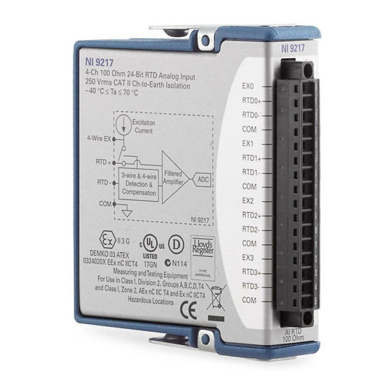
- Page 1 OPERATING INSTRUCTIONS AND SPECIFICATIONS NI 9217 4-Channel, 24-Bit, 100Ω RTD Analog Input Module Français Deutsch ni.com/manuals...
-
Page 2: Safety Guidelines
Visit ni.com/info about C Series documentation. Safety Guidelines Operate the NI 9217 only as described in these operating instructions. NI 9217 Operating Instructions and Specifications and enter rdsoftwareversion... -
Page 3: Safety Guidelines For Hazardous Voltages
You must use the NI 9939 connector backshell kit to ensure that the terminals are not accessible. © National Instruments Corp. This icon denotes that the component may be /60 VDC), you must ensure that devices NI 9217 Operating Instructions and Specifications... -
Page 4: Safety Guidelines For Hazardous Locations
Figure 1. NI 9939 Connector Backshell Safety Guidelines for Hazardous Locations The NI 9217 is suitable for use in Class I, Division 2, Groups A, B, C, D, T4 hazardous locations; Class I, Zone 2, AEx nC IIC T4, and Ex nC IIC T4 hazardous locations;... - Page 5 Follow these guidelines if you are installing the NI 9217 in a potentially explosive environment. Not following these guidelines may result in serious injury or death. Do not disconnect I/O-side wires or connectors Caution unless power has been switched off or the area is known to be nonhazardous.
- Page 6 II 3G and is suitable for use in Zone 2 hazardous locations. If you are using the NI 9217 in Gas Group IIC hazardous locations or in ambient temperatures of –40 °C ≤ Ta ≤ 70 °C, you must use the device in an NI chassis that has been evaluated as EEx nC IIC T4, Ex nA IIC T4, or Ex nL IIC T4 equipment.
- Page 7 Connecting the NI 9217 The NI 9217 has a 16-terminal, detachable screw-terminal connector that provides connections for four RTD channels. Figure 2. NI 9217 Terminal Assignments © National Instruments Corp. RTD0+ RTD0– RTD1+ RTD1– RTD2+ RTD2– RTD3+ RTD3– NI 9217 Operating Instructions and Specifications...
- Page 8 NI 9217. The NI 9217 channels share a common ground that is isolated from other modules in the system. Each channel is filtered and then sampled by a 24-bit analog-to-digital converter (ADC).
-
Page 9: Rtd0
Compensation NI 9217 Figure 3. Input Circuitry for One Channel of the NI 9217 in 4-Wire Mode Each channel has one terminal, RTD+, to which you connect the positive lead of the RTD signal and one terminal, RTD–, to which you connect the negative lead of the RTD signal. -
Page 10: Rtd0
RTD. If you are using a 3-wire RTD, do not connect the RTD to the EX terminal. For the best measurement results when using the NI 9217 with a 3-wire RTD, use equal-length wires between the RTD+ terminal and the RTD and between the COM terminal and the RTD. - Page 11 Wiring for High-Vibration Applications If an application is subject to high vibration, National Instruments recommends that you either use ferrules to terminate wires to the detachable screw-terminal connector or use the NI 9939 backshell kit to protect the connections. Refer to Figure 5 for an illustration of using ferrules.
-
Page 12: Sleep Mode
In sleep mode, the system consumes minimal power and may dissipate less heat than it does in normal mode. Refer to the Specifications section for more information about power consumption and thermal dissipation. NI 9217 Operating Instructions and Specifications ni.com... -
Page 13: Rtd1
ADC resolution... 24 bits Type of ADC... Delta-sigma Sampling mode ... Scanned Measurement range Temperature... –200 to 850 °C Resistance... 0 to 400 Ω Common-mode range COM-to-earth ground... ±250 V Channel-to-COM... 50 mV © National Instruments Corp. NI 9217 Operating Instructions and Specifications... - Page 14 Measured Value –200 to 150 °C 150 to 850 °C For high-speed mode, add a 0.1 °C error. NI 9217 Operating Instructions and Specifications 800 ms total for all channels 10 ms total for all channels , 4-wire mode Typical (25 °C) 0.15 °C...
-
Page 15: National Instruments Corp
High-speed mode ... None Common-mode rejection, channel to earth ground (50/60 Hz) High-resolution mode ... 170 dB min High-speed mode ... 155 dB Input bandwidth (high-resolution mode) ... 3.3 Hz © National Instruments Corp. NI 9217 Operating Instructions and Specifications... - Page 16 This image is provided courtesy of Linear Technology Corp. High-speed filter response has the same characteristics as the high-resolution filter response except that the first notch is at 14 kHz. NI 9217 Operating Instructions and Specifications Differential Input Signal Frequency (Hz)
-
Page 17: Power Requirements
Sleep mode ... 1 mW max Thermal dissipation (at 70 °C) Active mode ... 350 mW max Sleep mode ... 1 mW max © National Instruments Corp. Bellcore Issue 2, Method 1, Case 3, Limited Part Stress Method NI 9217 Operating Instructions and Specifications... -
Page 18: Physical Characteristics
Screw-terminal wiring ... 16 to 28 AWG copper Torque for screw terminals ... 0.22 to 0.25 N · m Ferrules ... 0.25 mm Weight... 142 g (5.0 oz) NI 9217 Operating Instructions and Specifications conductor wire with 7 mm (0.28 in.) of insulation stripped from the end (1.95 to 2.21 lb ·... -
Page 19: Isolation Voltages
The maximum voltage that can be applied between any channel or V a COM terminal without damaging the module or other devices. © National Instruments Corp. Category II dielectric withstand test NI 9217 Operating Instructions and Specifications , Measurement , verified by a 5 s terminal and... - Page 20 Do not connect the NI 9217 to signals or use for Caution measurements within Measurement Categories III or IV. Safety Standards This product is designed to meet the requirements of the following standards of safety for electrical equipment for measurement, control, and laboratory use: •...
- Page 21 Europe (DEMKO)... EEx nC IIC T4 Environmental National Instruments C Series modules are intended for indoor use only but may be used outdoors if installed in a suitable enclosure. Refer to the manual for the chassis you are using for more information about meeting these specifications.
-
Page 22: Shock And Vibration
Random (IEC 60068-2-64)... 5 g Sinusoidal (IEC 60068-2-6) ... 5 g, 10 to 500 Hz Operating shock (IEC 60068-2-27)... 30 g, 11 ms half sine, NI 9217 Operating Instructions and Specifications noncondensing noncondensing , 10 to 500 Hz 50 g, 3 ms half sine, 18 shocks at 6 orientations ni.com... -
Page 23: Electromagnetic Compatibility
2004/108/EC; Electromagnetic Compatibility Directive (EMC) Refer to the Declaration of Conformity (DoC) for Note this product for any additional regulatory compliance information. To obtain the DoC for this product, visit © National Instruments Corp. NI 9217 Operating Instructions and Specifications... -
Page 24: Environmental Management
Certification column. Environmental Management National Instruments is committed to designing and manufacturing products in an environmentally responsible manner. NI recognizes that eliminating certain hazardous substances from our products is beneficial not only to the environment but also to NI customers. -
Page 25: For Information
National Instruments ni.com/environment/rohs_china about China RoHS compliance, go to environment/rohs_china Calibration You can obtain the calibration certificate and information about calibration services for the NI 9217 at Calibration interval ... 1 year © National Instruments Corp. National Instruments RoHS ni.com/calibration... -
Page 26: Where To Go For Support
National Instruments corporate headquarters is located at 11500 North Mopac Expressway, Austin, Texas, 78759-3504. National Instruments also has offices located around the world to help address your support needs. For telephone support in the United States, create your service request at and follow the calling instructions or dial 512 795 8248. - Page 27 Sweden 46 (0) 8 587 895 00, Switzerland 41 56 2005151, Taiwan 886 02 2377 2222, Thailand 662 278 6777, Turkey 90 212 279 3031, United Kingdom 44 (0) 1635 523545 © National Instruments Corp. NI 9217 Operating Instructions and Specifications...
- Page 28 National Instruments, NI, ni.com, and LabVIEW are trademarks of National Instruments Corporation. Refer to the Terms of Use section on ni.com/legal for more information about National Instruments trademarks. Other product and company names mentioned herein are trademarks or trade names of their respective companies.