Table of Contents
Advertisement
Safety • Assembly • Operation • Adjustments • Maintenance • Troubleshooting • Parts Lists • Warranty
OPERATOR'S MANUAL
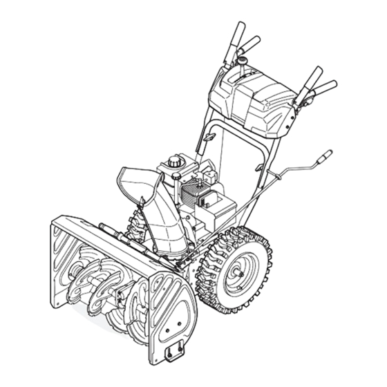
Two-Stage Snow Thrower — STORM 5524
IMPORTANT
READ SAFETY RULES AND INSTRUCTIONS CAREFULLY BEFORE OPERATION
Warning: This unit is equipped with an internal combustion engine and should not be used on or near any unimproved forest-covered, brush-
covered or grass-covered land unless the engine's exhaust system is equipped with a spark arrester meeting applicable local or state laws (if any).
If a spark arrester is used, it should be maintained in effective working order by the operator. In the State of California the above is required by law
(Section 4442 of the California Public Resources Code). Other states may have similar laws. Federal laws apply on federal lands. A spark arrester
for the muffler is available through your nearest engine authorized service dealer or contact the service department, P.O. Box 361131 Cleveland,
Ohio 44136-0019.
MTD LLC, P.O. BOX 361131 CLEVELAND, OHIO 44136-0019
PRINTED IN U.S.A
FORM NO. 769-01278C
06/17/2005
Advertisement
Table of Contents

Related Manuals for Troy-Bilt STORM 5524


Summary of Contents for Troy-Bilt STORM 5524
- Page 1 Safety • Assembly • Operation • Adjustments • Maintenance • Troubleshooting • Parts Lists • Warranty OPERATOR’S MANUAL Two-Stage Snow Thrower — STORM 5524 IMPORTANT READ SAFETY RULES AND INSTRUCTIONS CAREFULLY BEFORE OPERATION Warning: This unit is equipped with an internal combustion engine and should not be used on or near any unimproved forest-covered, brush- covered or grass-covered land unless the engine’s exhaust system is equipped with a spark arrester meeting applicable local or state laws (if any).
-
Page 2: Table Of Contents
. This information will be necessary to use the manufacturer’s web TROY-BILT LLC site and/or obtain assistance from the Customer Support P. O. BOX 3 6 1 1 3 1 www.troybilt.com... -
Page 3: Safety Labels
������ ������ �� ���� ���� ���� �������� �������� ��� ������ ������� ���� �������� �� ����� ��� �������� ����� ��� ����� ��� ��������� ���� �� ������ Safety �� ��������� ������ ��������� ������ ������� ���� ������� �� Labels ��� ������ ������ ������� ����� ��� ������... -
Page 4: Safe Operation Practices
WARNING: Engine Exhaust, some of its constituents, and certain vehicle compo- nents contain or emit chemicals known to State of California to cause cancer and birth defects or other reproductive harm. DANGER: This machine was built to be operated according to the rules for safe operation in this manual. - Page 5 Operation Maintenance & Storage 1. Do not put hands or feet near rotating parts, in the 1. Never tamper with safety devices. Check their proper auger/impeller housing or chute assembly. Contact with the operation regularly. Refer to the maintenance and adjust- rotating parts can amputate hands and feet.
-
Page 6: Setting Up Your Snow Thrower
Setting Up Your Snow Thrower NOTE: References to right or left side of the snow thrower are determined 1. Observe the lower rear area of the snow thrower to from behind the unit in the be sure both cables are aligned with roller guides operating position (standing before pivoting the handle upward. - Page 7 5. Remove the flat washer and hairpin clip from the end of the chute directional control. Insert the end of the chute directional control into the lower bracket and secure with the flat washer and hair- pin clip just removed. If necessary, the lower bracket can be adjusted.
-
Page 8: Operating Your Snow Thrower
Know Your Snow Thrower ����� ������� ����� ����� ����� ������� �������� ����� ������ Operating ����� �������� ��� ��� ����� ����������� ������� Your Snow ��� ���� Thrower ����� ��� ���� ������ �������� ������ ������� ������ �������� ������� ������ ������ �������� ��� WARNING �����... -
Page 9: Auger Control
Auger Control Ignition Key The ignition key is a safety devise. It must be fully ����� inserted in order for the engine to start. Remove the ������� ignition key when the snow thrower is not in use. Do not turn the ignition key in an attempt to start the engine. -
Page 10: Stopping The Engine
Gas & Oil Fill-Up 6. As the engine warms, slowly rotate the choke control to the OFF position. If the engine falters, quickly rotate Service the engine with gasoline and oil as instructed in the choke control back to FULL and then slowly into the Tecumseh Engines manual packed separately with the OFF position again. - Page 11 To Engage Augers 6. Wipe all snow and moisture from the area around the engine as well as the area in and around the drive 1. To engage the augers and start throwing snow, control and auger control. Also, engage and release squeeze the auger control against the left handle.
-
Page 12: Making Adjustments
Auger Control Refer to Auger Control Test on Page 11 to adjust the auger control. Shift Cable If the full range of speeds (forward and reverse) cannot be achieved, refer to the figures to the right and adjust Making the shift cable as follows: 1. - Page 13 Skid Shoes The space between the skid shoes and the ground can be adjusted. See Figure 6. • For close snow removal on a smooth surface, raise skid shoes higher on the auger housing. • Use a middle or lower position when the area to be cleared is uneven, such as a gravel driveway.
-
Page 14: Maintaining Your Snow Thrower
Engine Refer to the separate Tecumseh Engines manual packed with your unit for all engine maintenance. Lubrication Engine Maintaining Refer to the separate Tecumseh Engines manual packed with your unit for all engine lubrication instruc- Your Snow tions. Gear Shaft Thrower The gear (hex) shaft should be lubricated at least once a season or after every 25 hours of operation. - Page 15 Auger Belt Replacement To remove and replace your snow thrower’s auger belt, proceed as follows: 1. Remove the plastic belt cover on the front of the engine by removing the two self-tapping screws. NOTE: Drain the gasoline from the snow thrower, or Maintaining place a piece of plastic under the gas cap.
-
Page 16: Drive Belt Replacement
Augers • The augers are secured to the spiral shaft with two shear pins and cotter pins. If the auger should strike a foreign object or ice jam, the snow thrower is designed so that the pins may shear. Refer to Figure 9. •... -
Page 17: Friction Wheel Removal
Friction Wheel Removal If the snow thrower fails to drive with the drive control engaged, and performing the drive control cable adjust- ment on page 14 fails to correct the problem, the friction wheel may need to be replaced. Follow the instructions below. -
Page 18: Off-Seasonstorage
If the snow thrower will not be used for 30 days or longer, 1. Remove all gasoline from the carburetor and the fuel or if it is the end of the snow season when the last pos- tank to prevent gum deposits from forming on these sibility of snow is gone, the equipment needs to be stored parts and harming the engine. -
Page 19: Trouble-Shooting
3. Drain fuel tank. Refill with addresses minor fresh fuel. service issues. For 4. Carburetor out of adjustment. 4. Contact Troy-Bilt Service Center. further details, contact a Troy-Bilt authorized service center or call Engine overheats 1. Carburetor not adjusted properly. - Page 20 Style N � �� �� � � �� �� �� � �� �� �� �� � �� �� �� � � � � � � �� � � � � �� �� �� �� �� �� �� �� �� �� ��...
- Page 21 Bearing, Flange, .75 x 1.00 x .975 26. 790-00080 Bracket, Auger Idler w/ Brake 54. 746-04230 Clutch Cable, Auger, 47.23” 27. 618-04191 Gearbox Assembly, Auger, 24” 55. 629-0071 Extention Cord, 110V 28. 684-04077 Housing Ass’y, Troy-Bilt, Auger 24” 56. 737-3000 Grease Fitting, 3/16”...
- Page 22 Style N � � � � �� � �� �� � �� �� �� �� � � � �� �� � �� �� �� �� � �� �� � �� �� �� �� �� �� �� �� �� �� �� ��...
-
Page 23: Illustrated Parts List
631-04133 Handle Assembly, Lock, LH 24. 710-1260A Screw, 5/16-18, 0.75, Gr5 631-04134A Handle Assembly, Lock, RH 25. 714-0104 Pin, Cotter, .072 x 1.13 684-04105A Handle Ass’ y, Engagement LH 26. 720-0201A Crank Knob, 1.0 Dia. x 3.2, Black 684-04106A Handle Ass’y, Engagement, RH 27. - Page 24 Style N �� �� �� �� �� �� �� �� �� �� �� �� � �� �� �� �� �� �� �� �� �� �� �� �� �� �� � �� �� �� � �� �� �� �� � �� ��...
- Page 25 756-04177 Disc, Friction Wheel 37. 731-04873 Spacer, 1.25 x .75 x 3.0 684-04153 Friction Wheel Assembly, 5.5 OD 38. 738-04168 Axle, .75 x 22” 684-04154 Support Bracket, Friction Wheel 39. 741-0919 Ball Bearing 684-04156 Shift Assembly, Rod 40. 710-0106 Hex Screw, 1/4-20, 1.25, Gr5 710-0627 Hex Screw, 5/16-24, .750, Gr5 41.
- Page 26 NOTES...
- Page 27 NOTES...
-
Page 28: Warranty
MANUFACTURER’S LIMITED WARRANTY FOR The limited warranty set forth below is given by Troy-Bilt LLC with respect deck adjustments, and normal deterioration of the exterior finish to new merchandise purchased and used in the United States and/or its due to use or exposure.