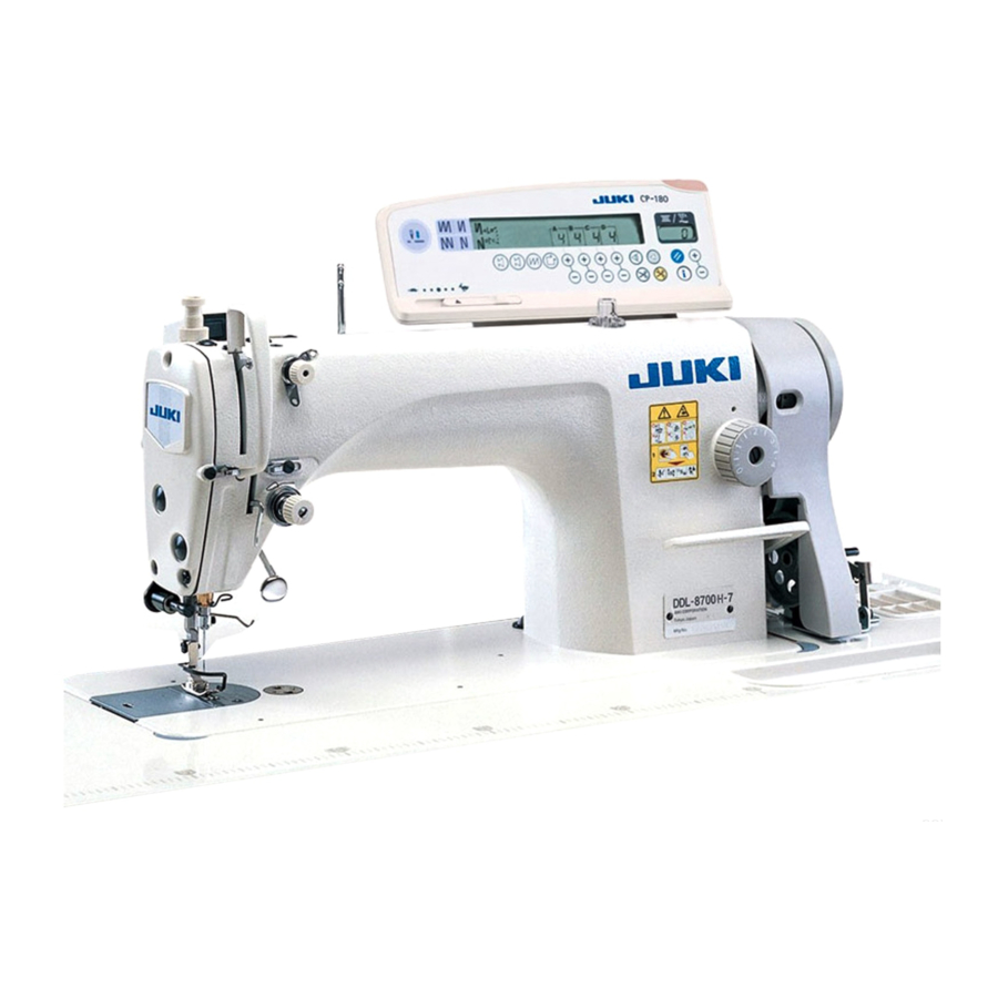
JUKI ddl-8700-7 Engineer's Manual
1-needle, lockstitch machine with automatic thread trimmer
Hide thumbs
Also See for ddl-8700-7:
- Instruction manual (88 pages) ,
- Specification (2 pages) ,
- Handbook (272 pages)

Related Manuals for JUKI ddl-8700-7


Summary of Contents for JUKI ddl-8700-7
- Page 1 ® 1-Needle, Lockstitch Machine with Automatic Thread Trimmer DDL-8700-7 ENGINEER’S MANUAL 40094273 No.E395-00...
- Page 2 PREFACE This Engineer’s Manual is written for the technical personnel who are responsible for the service and maintenance of the machine. The Instruction Manual for these machines intended for the maintenance personnel and operators at an apparel factory contains operating instructions in detail. It is advisable to use the Instruction Manual and Parts List for SC-920 together with this Engineer's Manual when carrying out the maintenance of these machines.
-
Page 3: Table Of Contents
CONTENTS 1. GENERAL ......................1 (1) Features ..........................1 (2) Applications ..........................1 2. SPECIFICATIONS ..................2 3. NAME OF EACH COMPONENT ..............4 4. ADJUSTMENT ....................6 (1) Adjustment of the belt tension ....................6 (2) Adjustment of the needle stop position ..................8 1) How to sdjust the upper stop position (after thread trimming) .......... - Page 4 (2) When using a bobbin case...................... 61 (3) How to correct irregular stitches produced at high/low speed ..........61 7. BRIEFLY CHECKING THE ADJUSTMENT OF THE THREAD TRIMMER OF DDL-8700-7 SERIES ......62 8. DRAWING OF THE TABLE ..............64...
-
Page 5: General
1. GENERAL (1) Features 1. The sewing speed can be changed continuously from low to high by adjusting the level of depression of the pedal, contributing to higher efficiency. 2. Performs automatic reverse feed stitching at the start and end of sewing. When the front part of the pedal is depressed, the machine carries out reverse feed stitching at constant speed, assuring consistent quality. -
Page 6: Specifications
(Max.112 mm to Min.105 mm) Lubrication Fully automatic By plunger pump Oil return JUKI NEW DEFRIX OIL No.1 or Lubricant JUKI MACHINE OIL 7 (equivalent to ISO VG7) Equipped (WB) Equipped (WB) Not equipped Wiper Automatic reverse Equipped as standard device... - Page 7 MEMO − 3 −...
-
Page 8: Name Of Each Component
3. NAME OF EACH COMPONENT ❹ ❷ ❾ ❸ ❽ ❶ ❻ ❺ ❼ Power switch Motor (M 92) Operation panel (CP-18, CP-180) Pedal Synchronizer One-touch type reverse feed switch L-shaped thread stand Wiper PSC box (SC-920) Adjusting screw for levelling the stand or caster −... - Page 9 ❶ Power switch Power switch of the motor, PSC and operation panel. ❷ Operation panel (CP-18, CP-180) Automatic reverse feed stitching, the stitch number of pattern sewing, etc. are set through this operation panel. ❸ Synchronizer Built inside the sewing machine pulley and used to detect the upper and lower positions of the needle and transmit input signal to the PSC box.
-
Page 10: Adjustment
4. ADJUSTMENT (1) Adjustment of the belt tension Standard adjustment belt ❶ − 6 −... - Page 11 Adjustment Procedure Results of Improper Adjustment 1. To avoid such problems, use a belt of an appropriate length as An excessive belt tension may specified in the INSTRUCTION MANUAL. damage the main shaft bushing 2. Adjust the belt tension using nut ❶ so that the middle of the of the machine or the motor bearing.
-
Page 12: Adjustment Of The Needle Stop Position
(2) Adjustment of the needle stop position Standard adjustment 1) How to sdjust the upper stop position (after thread trimming) Hand wheel ❶ 2) How to sdjust the lower stop position ❷ ❸ − 8 −... - Page 13 Adjustment Procedure Results of Improper Adjustment 1) How to adjust the upper stop position (after thread triming) 1. The standard upper needle stop position is such that the marker dot on the arm aligns with the white marker on the handwheel when the needle ❸ stops after thread trimming.
-
Page 14: Adjustment Of The Wiper (Wb Type)
(3) Adjustment of the wiper (WB type) Standard adjustment 1) Adjusting the position of the wiper ❶ ❷ ❸ ❹ ❻ ❺ − 10 −... - Page 15 Adjustment Procedure Results of Improper Adjustment Adjust the position of the wiper according to the thickness of materials to be sewn as follows: 1. Turn the handwheel in the normal rotational direction to align white dot ❶ on the handwheel with dot ❷ on the machine arm. 2.
-
Page 16: Theory Of Thread Trimming
(4) Theory of thread trimming 1) The blade point of the sewing hook catches the needle thread. 2) The moving knife spreads the threads. (goed back) 3) The moving knife hooks the needle and bobbin threads (advances). 4) The threads are trimmed. −... -
Page 17: Thread Trimming Sequence
(5) Thread trimming sequence Standard adjustment The knife hooks the threads. Tension release The knife spreads is terminated. the threads. The cam The front part Low to high speed The back part disengages of the pedal of the pedal The thread from the roller. -
Page 18: Adjustment Of The Timing Of The Thread Trimmer Cam
(6) Adjustment of the timing of the thread trimmer cam Standard adjustment 1) How to adjust the timing ❹ Turn the cam ❹ in this direction by hand. ❺ ❼ ❽ ❻ 2) How to adjust the timing of the thread trimmer cam ❸... - Page 19 Adjustment Procedure Results of Improper Adjustment 1) How to adjust the timing The timing of the thread trimmer cam ❹ for cotton and synthetic threads can be obtained simply by aligning the marker dot on the machine arm and the marker dot on the handwheel. 1.
-
Page 20: Adjustment Of The Position Of The Moving Knife
(7) Adjustment of the position of the moving knife Standard adjustment 1) Proper position of the moving knife 2) How to position the moving knife 3) When the moving knife can not be properly positioned merely by adjusting the position of the link driving magnet pin ❽... - Page 21 Adjustment Procedure Results of Improper Adjustment 1) Proper position of the moving knife 1. The correct position of the moving knife ❽ when the moving knife has gone back farthest is such that the tip of the moving knife is 3 to 3.5 mm away from the center of the needle.
-
Page 22: Adjustment Of The Counter Knife
(8) Adjustment of the counter knife Standard adjustment 1) Properly installing the knife thread guide 2) Adjusting the counter knife Bottom face of throat plate (bed) ❸ ❶ Center of needle ❷ Short Long Length of thread remaining on needle ❷... - Page 23 Adjustment Procedure Results of Improper Adjustment 1) Properly installing the knife thread guide Install the knife thread guide ❶ so that the needle enters exactly the center of its opening. 2) Adjusting the counter knife 1. The standard distance from the blade point of the counter knife ❷...
-
Page 24: Adjustment Of The Floating Amount Of The Tension Disc No. 2
(9) Adjustment of the floating amount of the tension disc No. 2 Standard adjustment 1) How to check the floating amount of the tension disc No. 2 Thread trimmer cam Turn the cam in this direction by hand. ❸ Screw No.2 Cam collar Roller ❹... - Page 25 Adjustment Procedure Results of Improper Adjustment 1) How to check the floating amount of the tension disc No. 2 Check whether the tension disc No. 2 ❹ floats 0.5 to 1 mm when thread take-up picker ❸ is pressed to the right with the thread take-up lever located slightly below its highest position and the presser foot lifted.
-
Page 26: Sharpening The Counter Knife
(10) Sharpening the counter knife Standard adjustment Sharpen this point well Sharpen this face (A face) Blade point (B face) ❶ ❶ ❷ ❷ C and D of moving knife must come in contact with ❶ counter knife at the same time. ❶... - Page 27 Adjustment Procedure Results of Improper Adjustment 1. The most important factor of the sharpness of the thread trimmer is the shape of the blade tip of the counter knife ❶. 2. In most cases, the sharpness of the thread trimmer can be improved by mere]y sharpening the blade of the counter knife ❶.
-
Page 28: Replacing The Moving Knife
(11) Replacing the moving knife Standard adjustment ❶ ❷ ❸ ❹ ❻ ❺ − 24 −... - Page 29 Adjustment Procedure Results of Improper Adjustment Remove the moving knife in the following order: 1. Loosen screw ❺. 2. Remove hinge screw ❸ using 3 mm Hex-head stick Spanner ❹. 3. Remove forked hinge screw ❶. Lift forked base ❷ for knife, and remove the moving knife pin from the forked base ❷...
-
Page 30: Replacing The Knife Thread Guide
(12) Replacing the knife thread guide Standard adjustment Bottom face of throat plate (bed) Moving knife ❹ Center of needle ❺ ❸ ❶ Short Long ❷ Length of thread remaining on needle − 26 −... - Page 31 Adjustment Procedure Results of Improper Adjustment 1. Change the knife thread guide ❹ by loosening screws ❷ and If there is no coincidence of the knife thread guide ❹ and the ❸, with screw ❶ left tightened. center the needle, this can be a 2.
-
Page 32: Adjustment Of The Thread Take-Up Picker
(13) Adjustment of the thread take-up picker Standard adjustment 1) Positioning the thread take-up picker 2) How to adjust the position of the thread take-up picker Thread triming unit Cloth link Marker line ❸ Picker link ❷ ❶ ❹ Picker arm ❸... - Page 33 Adjustment Procedure Results of Improper Adjustment 1) Positioning the thread take-up picker If thread take-up picker ❸ enters 1. With clutch disc ❶ pushed in the direction of arrow (to the the bobbin case too deeply at right), make adjustment so that the bobbin thread can be the time of thread trimming, the pulled out smoothly.
-
Page 34: Adjustment Of The Clutch Disc And Thread Trimmer Solenoid
(14) Adjustment of the clutch disc and thread trimmer solenoid Standard adjustment ❶ Thread trimmer solenoid stroke 6 mm Thread trimming Roller arm Ass’y ❸ ❷ ❶ − 30 −... - Page 35 Adjustment Procedure Results of Improper Adjustment 1. The thread trimmer solenoid ❶ stroke is 6 mm. 2. Position the clutch disc ❷ and trimmer solenoid ❶ so that, when the thread trimmer solenoid ❶ is actuated, clearance A becomes 0.1 mm to 0.5 mm. 3.
-
Page 36: Adjustment Of Driving Arm Stopper
(15) Adjustment of driving arm stopper Standard adjustment ❶ ❷ ❹ ❻ ❹ ❸ Needle ❺ ❺ Needle entry − 32 −... - Page 37 Adjustment Procedure Results of Improper Adjustment 1. Press the roller arm ❸ in the direction of arrow A until it is pressed against the stopper ❻ of the driving arm stopper ❹. 2. At this time, adjust screw ❶ and ❷ so that the stopper ❻ works at a position where the moving knife ❺...
-
Page 38: Adjustment Of The Knife Mounting Base
(16) Adjustment of the knife mounting base Standard adjustment ❺ ❻ ❶ ❷ ❼ ❸ ❽ ❹ − 34 −... - Page 39 Adjustment Procedure Results of Improper Adjustment Removing knife mounting base ❶ in the following sequence: 1. Remove the hook. 2. Remove the hinge screw ❷ of the picker link ❻, and take out the hinge screw ❸ of the picker arm ❼. 3.
-
Page 40: Adjustment Of The One-Touch Type Reverse Feed Switch Lever
(17) Adjustment of the one-touch type reverse feed switch lever Standard adjustment ❶ ❷ − 36 −... - Page 41 Adjustment Procedure Results of Improper Adjustment 1. There is no specified height for one touch reverse feed switch lever ❶, and therefore the one-touch type reverse feed switch lever may be positioned at any height suited for each operator. 2. Loosen screw ❷ and move the switch lever ❶ up and down to obtain a suitable height.
-
Page 42: How To Replace The Synchronizer
(18) How to replace the synchronizer Standard adjustment ❶ ❷ ❸ Hand wheel 1 ± 0.2 mm Stator mounting base Ass’ y − 38 −... - Page 43 Adjustment Procedure Results of Improper Adjustment If the synchronizer fails, the needle will not stop in the upper or lower position when the machine stops, causing the safety circuit to be put into operation, or the machine will keep on running at high speed when it should stop.
-
Page 44: Adjustment Of Normal/Reverse Stitching
(19) Adjustment of normal/reverse stitching Standard adjustment ❶ ❷ ❸ − 40 −... - Page 45 Adjustment Procedure Results of Improper Adjustment 1. Pinch a piece of paper beneath the presser hardware and set When the normal and reverse the feed dial graduation at 3. pitches are net same, the return 2. Remove the window plate on the sewing machine. stitches are in appropriate.
-
Page 46: Setting And Ajusting For Sc-920
(20) Setting and Ajusting for SC-920 1) Setting procedure of the machine head (Caution) For the operation panel other than CP-18, refer to the Instruction Manual for the operation panel to be used for the setting procedure of the machine head. 1. -
Page 47: Machine Head List
2) Machine head list Number of revolutions at Max. number of Machine head Type Contents of display the time of delivery (sti/min) revolutions (sti/min) DDL-9000B MA/MS/SS dLbM 4000 5000 DDL-9000B DS dLbd 4000 4000 DDL-9000B SH dLbH 4000 4500 dLAM 4000 5000 DDL-9000A MA/MS/SS... -
Page 48: Troubles And Corrective Measures
− 44 −... - Page 49 − 45 −...
- Page 50 − 46 −...
- Page 51 − 47 −...
- Page 52 − 48 −...
- Page 53 − 49 −...
-
Page 54: Sewing Performance
− 50 −... - Page 55 − 51 −...
- Page 56 − 52 −...
- Page 57 − 53 −...
- Page 58 − 54 −...
- Page 59 − 55 −...
- Page 60 − 56 −...
- Page 61 − 57 −...
- Page 62 − 58 −...
- Page 63 − 59 −...
- Page 64 − 60 −...
-
Page 65: Bobbin Case With An Idling Prevention Spring
6. BOBBIN CASE WITH AN IDLING PREVENTION SPRING The DDL-8700-7 use bobbin cases with an idling prevention springs. Adjust the tension of the an idling prevention spring as follows: If the bobbin races Increase the spring tension. If loose stitches result Decrease the spring tension. -
Page 66: Briefly Checking The Adjustment Of The Thread Trimmer Of Ddl-8700-7 Series
7. BRIEFLY CHECKING THE ADJUSTMENT OF THE THREAD TRIMMER OF DDL-8700-7 SERIES Confirm checkpoints ❶ through ❻ following the procedure described below. It is basically required to adjust the points properly. Start Turn ON the power to the sewing machine, and the... - Page 67 Cheakpoint ❸ 0.5 to 1 mm Confirm that the disk rises. Cheakpoint ❹ Engraved marker line Bobbin presser Confirrn that the picker has reached the engraved marker line. Tum the pulley in the Cheakpoint ❺ reverse direction of rotation until it stops. Confirm that the marker dot (red) engraved on the machine arm is...
- Page 68 MEMO − 64 −...
-
Page 69: Drawing Of The Table
ø35 through hole 2 - ø3.5 depth 4 2 - ø3.5 depth 10 ø13 through hole 2-ø3.5 depth 10 JUKI logo type 2-ø3.4 on the bottom surface, depth 10 (Drill a hole at the time of set-up) Rubber cushion installing drawing for reference C1.5 to C2.5 (For hinge side only) - Page 71 ISO14001 : 2004 REG.NO.JSAE389 CM001 Juki Corporation operates an environmental management system to promote and conduct the following as the company engages in the research, development, design, sales, distribution,and maintenance of industrial sewing machines, household sewing machines, industrial robots, etc., and in the provision of sales and maintenance services...