Table of Contents
Advertisement
Quick Links
Advertisement
Table of Contents

Related Manuals for Ericsson TRUNKED MDX


Summary of Contents for Ericsson TRUNKED MDX
- Page 1 LBI-33058 Operator’s Manual TRUNKED MDX MOBILE RADIO ericssonz...
-
Page 2: Table Of Contents
Ericsson Inc., at any time and without notice. Such changes will be incorportated into new editions of this manual. No part of this manual may be reproduced or transmitted in any form or by any means, electronic or mechanical, including photocopying and recording, for any purpose, without the express written permission of Ericsson Inc. - Page 3 TABLE OF CONTENTS (CON’T) Page SELECTING SYSTEM/GROUP ....20 Group Selection ....20 System Selection .
- Page 4 TABLE OF CONTENTS (CON’T) Page OPTIONS ......33 FREQUENTLY CALLED NUMBERS ... . . 34 WARRANTY .
-
Page 5: Safety Information
SAFETY INFORMATION The operator of any mobile radio should be aware of certain hazards common to the operation of vehicular radio transmissions. A list of possible hazards are: 1. Explosive Atmospheres Just as it is dangerous to fuel a vehicle with the motor running, be sure to turn the radio off while fueling the vehicle. -
Page 6: Safe Driving Recommendations For Users Of Mobile Radios
5. Liquefied (LP) Gas Powered Vehicles Mobile radio installations in vehicles powered by liquefied petroleum gas with the LP gas container in the trunk or other sealed-off space within the interior of the vehicle must conform to the standard which requires that: The space containing the radio equipment shall be isolated by a seal from the space containing the LP gas container and its... -
Page 7: Introduction
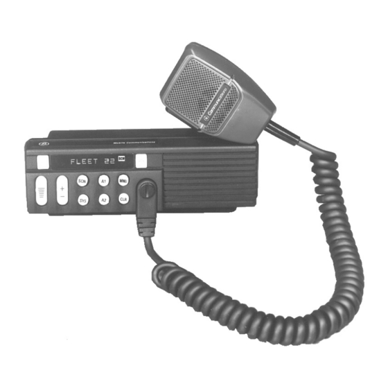
INTRODUCTION This manual describes how to use the Trunked MDX Mobile Radio. The MDX is a synthesized, microprocessor-based, high performance mobile FM radio providing reliable two-way communications in trunking environments. Direct mobile to mobile communication, when out of repeater range, is also provided. -
Page 8: Controls, Indicators, And Displays
CONTROLS, INDICATORS, AND DISPLAYS The MDX Scan radio with an internal speaker contains ten buttons, an eight character DOT MATRIX display and seven indicators. The MDX System radio contains ten buttons, an eight character DOT MATRIX display and seven indicators along with a twelve button keypad. The system radio uses an external speaker. - Page 9 PUBLIC ADDRESS: Press the MENU button until "PUB ADDR" appears in the display. Press PTT to transmit in PA mode. SCAN ADD/DELETE: Press the MENU button until "SCAN A/D" appears in the display. Use the GROUP/SEL- button to step through the group selections for the current system.
-
Page 10: Controls And Indicators
CONTROLS AND INDICATORS 8-Character MENU button allows Emergency ID/ Alphanumeric Dot access to functions Alarm (optional) Matrix LED and options, sends an emergency allows you to identify including alert and identifying group and system pre-programmed code to the selections by telephone dispatcher. - Page 11 8-Character MENU button allows Emergency ID/ Flex Key Alphanumeric Dot access to functions Alarm (optional) give you one-touch Matrix LED and options, sends an emergency access to the menu or allows you to identify including alert and identifying optional features. group and system pre-programmed code to the...
- Page 12 CONTROLS (CONT’D) Momentary switch. The SYS (SYSTEM) button is used to select system changes. System may be incremented by pressing and releasing the SYS button. Alternately, when the display shows the System name, the GROUP/SEL buttons may be used to increment or decrement the system selec- tions.
-
Page 13: Display Indicators
DISPLAY INDICATORS The radio’s display is shown below. The character line is used to display system or area and group or channel names and also operational messages to the user. The line contains eight Dot Matrix LED characters. The 7 status indicators are used to show the various operating conditions of the radio. -
Page 14: Full Length Indicators
or left of the display (PC programmable). It is separated from the normal information with an indicator such as an asterisk ("*"). Full Length Indicators **INDV** Displayed when your unit receives an individual call from another unit. ID##### If programmed, displayed when your unit receives an individual call where ##### is the unit ID of the calling radio. -
Page 15: Alert Tones
ALERT TONES The trunked MDX radio generates a set of unique alert tones to indicate operating status. The following section identifies and describes the alert tones used in the MDX radio for trunked applications. -
Page 16: Trunked Alert Tone Sets
CALL DISABLED You will hear a continuous low pitched tone when ALERT your radio is set to an Rx (decode) only group/channel and you press PTT on the micro- phone. This tone indicates that you are not allowed to place a call on this setting. CARRIER CONTROL The Carrier Control Timer alert is a low pitched TIMER... -
Page 17: Continuous Alert Tones
Continuous Alert Tones CALL QUEUED If you hear two short, high pitched beeps after you key the microphone, the system has placed your request in a queue. The tones sound at both your transmitting unit and the receiving unit(s). This indicates to the receiving unit(s) that they will receive a call shortly. -
Page 18: Definition Of Terms
DEFINITION OF TERMS System The term system refers to the particular group of station repeaters and set of group/special calls pro- viding service to the radio. Radios can be prepro- grammed to work in different systems by changing the systems selection or through wide area roam- ing. -
Page 19: Prosound
Each trunked system may also have a priority trunked system associated with it when set to a system with a priority system programmed, the radio periodically checks for the priority system. If found, it automatically switches to that system. The timer is reset every time the PTT button is pressed to avoid interrupting a conversation. -
Page 20: Selecting System/Group
SELECTING SYSTEM/GROUP Use the GROUP/SEL and SYStem controls to select a different Group or System. Group Selection 1. If the unit is in Menu Mode, press and release the CLR button to return the radio to normal operation. 2. Press the GROUP/SEL + or - ramp button until the desired Group name appears in the alphanumeric display. -
Page 21: Microphone Public Address Operation
Set the ON/OFF switch on the option box to the ON position to select the external speaker and disable the internal speaker. Place in OFF position to select the internal speaker only. Press the A1 or A2 button (pre-programmed) to select the external speaker and disable the internal speaker. -
Page 22: Manually Entering A Group Id (System Model Only)
NOTE If the group you wish to transmit on is not in the list, a properly programmed System Model MDX has the capability of operating on a user selected group ID. 2. Press and hold down the PTT button. 3. You will hear a short beep (unless the radio is programmed to mute the beeps) indicating that you have access to the system. -
Page 23: Receiving An Emergency Message
NOTE It is recommended that a null group be programmed into the first location initially. This will avoid overwriting a desired group from the list unintentionally. RECEIVING AN EMERGENCY MESSAGE From The Selected Group When an emergency is received from a member of your selected group, "EMERGNCY"... -
Page 24: Clearing An Emergency
3. Release the PTT button when the transmission is complete, and listen for any reply. The TX indicator will go out when you release the PTT button. CLEARING AN EMERGENCY If your radio has been programmed as a supervisory unit, you may clear emergency calls. -
Page 25: Answering A Telephone Interconnect Call
NOTE Your MDX radio is capable of simplex (one way) conversation only. The person you are talking to can hear you ONLY when you have the PTT button pressed. You can hear the person on the telephone ONLY when the PTT button is released. If you leave the PTT button released for too long, the system will send three beeps. -
Page 26: Group Scan Operation
Receiving An Individual Call When you receive an Individual Call (call directed only to your radio), the display changes to one of the following displays: 1. "*INDV*" 2. "IDxxxxx", where XXXXX is the numeric ID of the calling radio 3. "ALPHA", where ALPHA is the alpha name of the calling radio Receiving an Individual Call will also cause the BSY indicator to turn on. -
Page 27: Starting Or Stopping Scan
Starting Or Stopping Scan 1. Press the SCAN button until either the "SCN" indicator goes off or NOTE 1. The radio will remember the scan state through a power cycle unless programmed with a predefined power up state. 2. The radio may be programmed to stop scanning when the micro- phone is removed from teh hookswitch. -
Page 28: Mobile Data Terminal Interface (Optional)
METHOD 3: Returning the Microphone to the hang-up bracket (enabled through programming). NOTE If a channel disconnect occurs before the conversation ended, the call must be initiated again. To avoid confusion it is recommended that a procedure be set up so that the originator of the call is the one designated to re-establish communications. -
Page 29: Scan Lockout Mode
SCAN LOCKOUT MODE Following the transmission or reception of a data call, if scan is enabled, scanning will stop temporarily (duration pre-programmed). During this time the scan LED will flash to indicate that scan is enabled but temporarily suspended. This mode is normally exited when the pre-programmed time expires;... -
Page 30: Message Operation
2. When the desired status is displayed, press the PTT switch to send the status to the site or stored in the radio memory where it can be polled by the site at a future time. If the site does not receive the status properly, the radio will sound a low pitched tone. -
Page 31: Emergency Operation
Emergency Operation If the pre-programmed groupset on the currently selected system contains an EMERGENCY/HOME group and the radio is in dynamic regroup, the radio will exit dynamic regroup and declare the emergency on the HOME group. If no EMERGENCY/HOME group is present, the radio will declare the emer- gency on the currently selected dynamic regroup group. -
Page 32: Aegis Digital Mode
AEGIS DIGITAL MODE Aegis digital mode allows the radio to transmit and received digitized voice signals. Aegis digital signals provide improved weak signal performance and they cannot be easily monitored with a standard receiver. Groups and channels programmed for Aegis digital operation transmit only digital signals. Message trunked group calls and individual calls will be answered back in the mode in which they were received, assuming the call or hang time is still active. -
Page 33: Options
Speaker, MIL-STD-810 C & D, 5" x 5", 19A149590P1 GE logo, requires options PMCD7Z & PMCC9M PMLS1H Speaker, MIL-STD-810 C & D, 5" x 5" 19A149590P11 Ericsson Logo, requires options PMCD7Z & PMCC9M PMMA1M Mounting bracket 19C138051G11 PMMK3D Keycap kit w/removal tool 344A4254G2... -
Page 34: Frequently Called Numbers
FREQUENTLY CALLED NUMBERS MEMORY LOCATION NAME TELEPHONE NUMBER... -
Page 35: Warranty
WARRANTY Ericsson Inc. (hereinafter "Seller") warrants to the original purchaser for use (hereinafter "Buyer") that Equipment manufactured by Seller shall be free from defects in material, workmanship and title, and shall conform to its published specifications. With respect to any Equipment not manufactured by Seller (except for integral parts of Seller’s Equipment to which the warranties set forth above shall apply). -
Page 36: Operating Tips
(particularly if a glass mount antenna is used). Moving a few yards in another direction or moving to a higher elevation may also improve communications. Ericsson Inc. Private Radio Systems Mountain View Road...