Table of Contents
Advertisement
Quick Links
Download this manual
See also:
Maintenance Manual
SERVICE SECTION
FOR
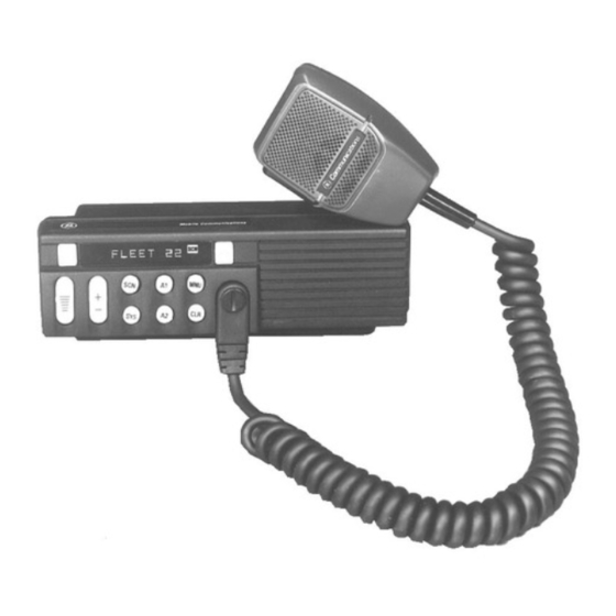
MDX GE-MARC 800 MHz RADIO
TABLE OF CONTENTS
DESCRIPTION............................................................................................................................................................
INITIAL ADJUSTMENT..............................................................................................................................
RECEIVER ADJUSTMENT.........................................................................................................................
RE-INSTALLATION ....................................................................................................................................
PREVENTIVE MAINTENANCE ...............................................................................................................................
CONNECTIONS ...........................................................................................................................................
ELECTRICAL SYSTEM...............................................................................................................................
MECHANICAL INSPECTION.....................................................................................................................
ANTENNA ....................................................................................................................................................
ALIGNMENT................................................................................................................................................
FREQUENCY CHECK .................................................................................................................................
STATIC HANDLING PRECAUTIONS......................................................................................................................
DISSASSEMBLY PROCEDURES .............................................................................................................................
TO REMOVE BOTTOM COVER ................................................................................................................
TO REMOVE TOP COVER .........................................................................................................................
TO REMOVE RF BOARD............................................................................................................................
TO REMOVE THE FRONT CAP ASSEMBLY...........................................................................................
TO REMOVE THE AUDIO AMPLIFIER BOARD .....................................................................................
TO REMOVE THE AUDIO BOARD ...........................................................................................................
TO REMOVE LOGIC BOARD ....................................................................................................................
TO REMOVE THE PA BOARD...................................................................................................................
TO REMOVE THE DISPLAY BOARD .......................................................................................................
COMPONENT REPLACEMENT ...............................................................................................................................
SURFACE MOUNTED COMPONENTS.....................................................................................................
To Remove Surface Mounted Components ............................................................................................
To Replace Surface Mounted Components.............................................................................................
To Replace Surface Mounted Integrated Circuits ...................................................................................
TROUBLESHOOTING PROCEDURES ....................................................................................................................
Power On Self Diagnostic.......................................................................................................................
SYMPTOMS AND CHECKS......................................................................................................................................
LBI-38973
1
1
1
1
1
1
1
1
1
1
1
1
2
2
2
2
2
2
2
2
2
3
3
3
3
3
3
4
4
4
Printed in U.S.A.
Advertisement
Chapters
Table of Contents

Summary of Contents for Ericsson MDX GE-MARC
- Page 1 LBI-38973 SERVICE SECTION MDX GE-MARC 800 MHz RADIO TABLE OF CONTENTS DESCRIPTION................................INITIAL ADJUSTMENT..........................RECEIVER ADJUSTMENT......................... RE-INSTALLATION ............................ PREVENTIVE MAINTENANCE ..........................CONNECTIONS ............................ELECTRICAL SYSTEM..........................MECHANICAL INSPECTION........................ANTENNA ..............................ALIGNMENT..............................FREQUENCY CHECK ..........................STATIC HANDLING PRECAUTIONS........................DISSASSEMBLY PROCEDURES ..........................TO REMOVE BOTTOM COVER ........................
- Page 2 CONNECTIONS APPENDIX A - GE-MARC TONES..........................which they are used. Ground connections to the voltage source should be periodically checked for tightness. Loose or poor Copyright © August 1993, Ericsson GE Mobile Communications Inc.
-
Page 3: Dissassembly Procedures
LBI-38973 LBI-38973 To prevent damage from ESD, observe the following Disconnect wires attached to J704, J705 and cables going TO REMOVE THE AUDIO BOARD DISASSEMBLY PROCEDURES precautions: to the PA Board. Remove the top and bottom covers from the radio. Refer •... -
Page 4: To Remove The Display Board
Do not apply heat for an TO REMOVE THE DISPLAY BOARD excessive length of time and do not use excessive The MDX GE-MARC 800 MHz mobile radio is divided solder. Remove the top and bottom covers and Front Cap into 6 Boards or assemblies. To aid in identifying the suspec- Assembly as directed above. -
Page 5: Power On Self Diagnostic
If the audio is correct at VOL/SQ HI, and the Tx Audio input. If all signals are check the Rx audio out. If improper, To test the MDX GE-MARC radio, a test mode must be correct, the problem is likely a faulty Audio Control Panel. -
Page 6: Channel Frequency Select
LBI-38973 LBI-38973 TRANSMITTER TEST: S 0 1 (ON) ACROSS BAND SWITCHING: S 1 0 TEST MODE COMMANDS NOTE (OFF) To determine the channel number, use the following This function continuously toggles the synthesizer across Plug the handset and adapter cable into the test point box. formula: The carrier is ON/OFF at the specified channel the band between 806.0125 and 825.9875 MHz. -
Page 7: Transmitter Frequency
MHz IF offset (TMX-8825) and on J1-2 and 3 for radios frequency. with 45.3 MHz IF offset (MDX GE-MARC). This function toggles the relay line at a 1000 Hz rate for board level testing. Any key causes reset to default conditions. -
Page 8: Transmitter Alignment
LBI-38973 LBI-38973 IF Tuning TRANSMITTER ALIGNMENT ALIGNMENT PROCEDURE Monitor J501 pin 1 with an AC voltmeter (pin 2 is Frequency Set ground). Inject an on-channel signal at the antenna jack modulated with a 1 kHz tone at 3 kHz deviation. Select any channel frequency. -
Page 9: Rf Board
LBI-38973 LBI-38973 Audio Board APPENDIX A. GE-MARC TONES A+ (+13.8 volts nominal) enters the radio on the power Regulator U606 receives SW A+ power and cable and is connected to the system board. A+ feeds generates 8 volt power for the audio devices on the board. Number Frequency Number... - Page 10 LBI-38973 BLOCK DIAGRAM LBI-38973 (19D904183 Sh. 1, Rev. 2)
- Page 11 LBI-38973 BLOCK DIAGRAM LBI-38973 (19D904183 Sh. 5 & 6, Revs. 3 & 3)
- Page 12 LBI-38973 BLOCK DIAGRAM LBI-38973 MDX GE-MARC 800 MHz Power Distribution Diagram...
- Page 13 LBI-38973 BLOCK DIAGRAM LBI-38973 MDX GE-MARC 800 MHz Audio Signal Flow...
- Page 14 LBI-38973 BLOCK DIAGRAM LBI-38973 MDX GE-MARC 800 MHz Data Control Diagram...


