Table of Contents
Advertisement
Quick Links
Advertisement
Table of Contents

Related Manuals for Multitech MULTI MODEM II MT5600BL


Summary of Contents for Multitech MULTI MODEM II MT5600BL
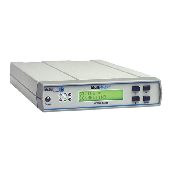
- Page 1 Model MT5600BA Model MT5600BL Data/Fax Modem User Guide...
- Page 2 BBS references and digital loopback tests; and update phone numbers, regulatory agency statements, firmware upgrade instructions, Web links, and modem package components list. Trademarks MultiModemII, Multi-Tech, and the Multi-Tech logo are trademarks of Multi-Tech Systems, Inc.
- Page 3 FCC Part 15 NOTE: This equipment has been tested and found to comply with the limits for a Class B digital device, pursuant to Part 15 of the FCC Rules. These limits are designed to provide reasonable protection against harmful interference in a residential installation. This equip- ment generates, uses, and can radiate radio frequency energy, and if not installed and used in accordance with the instructions, may cause harmful interference to radio communications.
-
Page 4: Table Of Contents
Chapter 2: Installation Introduction ... 6 What You Will Need ... 6 Safety Warnings ... 6 Step 1: Connect the Modem to Your System ... 7 RS232 Connection ... 7 Dialup Connection ... 7 Two-Wire Leased Line Connection ... 8 Four-Wire Leased Line Connection ... - Page 5 Chapter 8: Solving Problems Introduction ... 72 None of the Indicators Light ... 72 The Modem Does Not Respond to Commands ... 73 The Modem Cannot Connect When Dialing ... 74 The Modem Disconnects While Online ... 75 The Modem Cannot Connect When Answering ... 76 File Transfer Is Slower Than It Should Be ...
- Page 6 Standard Linux Serial Port Definitions ... 98 Installation ... 98 Setup ... 98 Using the Terminal Program Minicom to Verify Operation ... 98 Using the Modem to Call the Internet ... 99 Calling the ISP ... 99 Answering Calls ... 99 Appendix G: Pin Descriptions RS-232 Pin Descriptions ...
-
Page 7: Chapter 1: Introduction
Introduction... -
Page 8: Introduction
Congratulations on your purchase of the MultiModemII modem. You have acquired one of the finest intelligent data/fax modems available today from one of the world’s oldest modem manufacturers: Multitech Systems, Inc. This user guide will help you install, configure, test and use your modem. - Page 9 MultiModemII User Guide Data • Supports K56flex 21.6K, 19.2K, 16.8K, 14.4K, 12K, 9.6K, 7.2K, 4.8K, 2.4K, 1.2K, and 0–300 bps. Note: Under the 56K bps standards, you can asymmetrically download data from an ISP at speeds up to 53K bps, but upload only at speeds up to 33.6K bps. Client- to-client operation, including leased line operation, is also limited to 33.6K bps.
-
Page 10: What Is In Your Modem Package
MultiModemII User Guide What Is in Your Modem Package? Your modem package has several components. Make sure you have them all before trying to operate your modem. Your package should include: • An MT5600BA or MT5600BL modem A power transformer •... -
Page 11: Chapter 2: Installation
Installation... -
Page 12: Introduction
An MT5600BA or MT5600BL modem A power transformer Country-specific telephone cordage A 9-pin to 25-pin serial cable (international modem kits only) A printed Quick Start Guide An installation CD containing modem drivers and this User Guide A CD containing data communications and other programs... -
Page 13: Step 1: Connect The Modem To Your System
Figure 2-1. MT5600BL connections. RS232 Connection Plug one end of the serial cable into the RS232 connector on the modem, and the oth- er end into a serial port connector on your computer, such as COM1 or COM2. Dialup Connection Plug one end of the modular phone cable into the modem’s LINE jack, and the other... -
Page 14: Two-Wire Leased Line Connection
Power surges and other transient voltages on power lines, such as those caused by lightning strikes, can damage or destroy your modem. Therefore, we recommend that you plug the modem into a surge protector rather than directly into a wall out- let, preferably a surge protector that provides protection against electrical spikes on the phone line as well as on the power line. -
Page 15: Step 2: Install The Modem Driver
Windows, and the old modem driver is still selected in HyperTerminal and other Windows applications. Though you can change the application connection descrip- tions one at a time, it is easier to force Windows applications to use the new modem by removing the old modem driver from Windows. -
Page 16: Step 3: Install And Configure Your Software
1. Turn on your computer and run your communication program. 2. Find the dialog box or menu that lets you select your modem. (In Windows Ter- minal select Settings | Modem Commands; in HyperTerminal select File | Properties | Phone Number;... -
Page 17: Chapter 3: Using The Front Panel
Using the Front Panel... -
Page 18: Introduction
“Step 3: Install and Configure Your Software” in Chapter 2 for help in setting up your communication program. You also can configure your modem either through the front panel or by sending AT commands to the modem. This chapter describes how to configure it using the front panel. -
Page 19: Liquid Crystal Display (Lcd)
MultiModemII User Guide Terminal Ready. The TR indicator lights when a communication program is using the modem. It means the modem is ready for an outgoing or incoming call. It goes off when the communication program disconnects the serial port. -
Page 20: Menu Overview
MultiModemII User Guide 3 Using the Front Panel Menu Overview Trunks Limbs Branches Twigs Manual selection Automatic selection... -
Page 21: Status Trunk
The Status Trunk shows the current operating status of the modem. Limb changes are automatic, but certain options can be accessed by pressing the à button. Note that when the modem is online, pressing the à button shows the connect status, in- cluding the data speed, connection type, and compression type. -
Page 22: Basic Options Trunk
MultiModemII User Guide Basic Options Trunk Use the Basic Options Trunk to configure the modem’s basic operating conditions. When entering a number, use the á ß and â buttons to scroll through a list of digits and characters. To go to the next position, press the à button. To back up or to exit without dialing, press the à... - Page 23 MultiModemII User Guide 3 Using the Front Panel Basic Options Trunk, continued Limbs Branches Twigs Continued from previous page...
-
Page 24: Advanced Options Trunk
MultiModemII User Guide Advanced Options Trunk Use the Advanced Options Trunk to configure RS-232, dial backup, and callback se- curity options. When entering a number or password, use the á ß and â buttons to select a character or digit. To go to the next position, press the à button. To back- space or to exit, press the à... - Page 25 MultiModemII User Guide 3 Using the Front Panel Advanced Options Trunk, continued Limbs Branches Twigs Continued from previous page...
-
Page 26: Remote Configuration Options Trunk
à button. To backspace or to exit, press the à button several times. Limb Diagnostic Options Trunk Use the Diagnostic Options Trunk to run loopback tests on the modem. When a test is in progress, the TM indicator lights. Limb Branches... -
Page 27: Phone Number Memory Options Trunk
MultiModemII User Guide Phone Number Memory Options Trunk The MultiModemII can store up to four telephone numbers for speed dialing. Use the Phone Number Memory Options Trunk to store, list, and dial these numbers. When entering a number, use the á ß and â buttons to scroll through the available digits and dialing commands. -
Page 28: Menu Options
STATUS = IDLE. The modem is ready but inactive. This screen appears when the modem is first turned on, and is the starting point for accessing all other screens. Three options are available from this screen by pressing the à button: STATUS = ONLINE. -
Page 29: Basic Options
MultiModemII User Guide Basic Options The following screens are used to configure the modem’s basic operating conditions. ONLINE OPTIONS. The following screens are used to configure the online opera- tion of the modem: DIALING OPTIONS. The following screens are used to configure dialing options or to dial manually. - Page 30 Same as the AT&F&W command string. CONNECT RATE OPTIONS. Use the à and Enter buttons to change the modem’s serial port and data transmission speeds. ENABLE/DISABLE RESPONSE. Use the à and Enter buttons to enable or disable the sending of result codes to the computer.
-
Page 31: Advanced Options
“Leased Line Operation.” DTR OPTIONS. Use the à and Enter buttons to select how the modem responds to the high to low transition of the DTR signal sent by the computer. DTR NORMAL causes the modem to hang up; IGNORE DTR allows operation with computers that do not provide DTR;... - Page 32 MultiModemII User Guide CALLBACK SECURITY. Use the à and Enter buttons to turn callback security on or off. Same as the #DB0 and #DB1 commands. For more information about callback security, see Chapter 6, “Callback Security.” S-REGISTER OPTIONS. Use the à, â, and Enter buttons to display the current S-register values and enter new values.
-
Page 33: Remote Configuration Options
MultiModemII User Guide Remote Configuration Options The following screens are used to configure remote configuration options. For more information about remote configuration, see Chapter 5, “Remote Configuration.” Diagnostic Options Use the following screens to turn loopback tests on and off. For information about how to apply these tests, see Appendix C, “Loopback Tests.”... -
Page 34: Caller Id Options
Caller ID, or to disable Caller ID altogether. Same as the #CID=0, #CID=1, and #CID=2 commands. Note: Because Caller ID information is sent between the first and second ring, regis- ter S0 must be set to 2 or more rings for the modem to receive Caller ID information. 3 Using the Front Panel... -
Page 35: Chapter 4: At Commands, S-Registers & Result Codes
AT Commands, S-Registers & Result Codes... -
Page 36: Introduction
MultiModemII User Guide Introduction AT commands are used to control the operation of your modem. They are so called because each command must be preceded by the characters AT to get the ATtention of the modem. AT commands can be issued only when the modem is in command mode or online command mode. -
Page 37: At Commands
AT. Do not press E Communication Standard Setting n = 0 or 1 Selects ITU-T V.22 mode when the modem is at 300 or 1200 bps. Selects Bell 212A when the modem is at 300 or 1200 bps. - Page 38 Description: 4 AT Commands, S-Registers, and Result Codes @ Wait for silence. Causes the modem to wait for 5 seconds of silence before processing the next part of the command. If silence is not detected within the time set in register S7, the modem returns a NO ANSWER or BUSY code.
- Page 39 = 0, 1, 2, or 3 Speaker is always off. Speaker is on until the carrier signal is detected. Speaker is always on when the modem is off-hook. Speaker is off when receiving carrier and during dialing, but on during answering.
- Page 40 MultiModemII User Guide Command: Values: Default: Description: Command: Values: Default: Description: Command: Values: Default: Description: Command: Values: Default: Description: Command: Values: Default: Description: Command: Values: Default: Description: Command: Values: Default: Description: Command: Values: Default: Description: 4 AT Commands, S-Registers, and Result Codes Return Online to Data Mode 0 or 1 None...
- Page 41 Result Code Selection n = 0–4 This command selects which subset of the result messages will be used by the modem to inform the computer of the results of commands. Sends OK, CONNECT, RING, NO CARRIER, ERROR and NO ANSWER; does not look for dial tone or busy signal.
- Page 42 &Q2, &Q3: DTR drop causes the modem to hang up. Autoan- swer is inhibited. &Q5 or &Q6 and +FCLASS=1 or +FCLASS=2: Same as for &Q0. Note: If &D1, &D2, or &D3 is set, the modem will not dial without a DTR drop. &E n V.42 Error Correction Modes n = 0, 1, or 2 &E0...
- Page 43 Values: Default: Description: Command: Values: Default: Description: 4 AT Commands, S-Registers, and Result Codes &E n Modem-Initiated Flow Control n = 3, 4, or 5 &E3 Flow control disabled. &E4 CTS/RTS hardware flow control. &E5 XON/XOFF software flow control. Note: See also the L5 and &K commands.
- Page 44 &M2 Selects synchronous connect mode with asynchronous offline command mode. Same as &M1 except that &M2 enables DTR dialing of directory slot 0. The modem disconnects if DTR is low for more than the period stored in S25. &M3 Selects synchronous connect mode. This mode allows DTR to act as a talk/data switch.
- Page 45 None The modem can perform selected test and diagnostic functions. A test can be run only when the modem is in asynchronous op- eration in non-error-correction mode (normal or direct mode). For tests 3, 6, and 7, a connection between the two modems must first be established.
- Page 46 &W n Store Current Configuration n = 0 or 1 None &W0 Stores current modem settings in nonvolatile memory as Profile 0. Profile 0 is loaded instead of the factory defaults at power-on (if &Y0 is set) and by the ATZ command.
- Page 47 = 0 or 1 Specifies the PCM code type for 56K modulation. Note, how- ever, that the modem automatically selects the code type if the server sends the proper ID. %U0 Selects µ-Law coding—used in North America and Japan.
- Page 48 \K n Break Control n = 0–5 Controls the response of the modem to a break received from the computer, the remote modem, or the \B command. The response is different for each of three different states. Data mode. The modem receives the break from the computer: Enter online command mode;...
- Page 49 V.42/MNP reliable (error-correction) mode. The modem at- tempts first a V.42 connection and then an MNP connection. Failure to make a reliable connection results in the modem hanging up. (Forces &Q5, S36=4, and S48=7.) V.42/MNP auto-reliable mode. The modem attempts first to connect in V.42 mode, then in MNP mode, and finally in non-...
- Page 50 1 = Enable automode (default) min_RX_rate An optional number that specifies the lowest rate at which the modem may establish a receive connection. The value is decimal coded in units of bps, e.g., 2400 specifies the lowest rate to be 2400 bps. See “Possible rates” in the mod table.
- Page 51 0 = µ-Law—used in North America and Japan (default) 1 = A-Law—used outside North America and Japan The modem automatically selects A-Law or µ-Law if the server sends the Conexant ID. Note that the ATZ command restores the x_law value from NVRAM. You can also manually select A-Law or µ-Law using the %U command.
- Page 52 MultiModemII User Guide Command: Values: Description: Command: Values: Description: Command: Values: Description: Command: #CBN y =[-] x Store Callback Number Values: Default: Description: Command: #CBP y = x Store Callback Password Values: Default: Description: 4 AT Commands, S-Registers, and Result Codes ** n Flash Memory Download n = 0, 1, or 2...
- Page 53 #CID=1 Enables formatted Caller ID reporting of ICLID SDM (Single #CID=2 Enables unformatted Caller ID reporting of any ICLID packet #CID? #CID=? Returns the mode capabilities of the modem in a list with each Command: #DB n Callback Enable/Disable Values:...
-
Page 54: S-Registers
MultiModemII User Guide S-Registers Certain modem values, or parameters, are stored in memory locations called S- registers. Use the S command to read or alter the contents of S-registers (see previ- ous section). Register Unit 1 ring 1 ring decimal 0–127 decimal 0–127... - Page 55 A zero value disables dial backup. Sets the length of time the modem waits af- ter after a lease line fails before it attempts a dial-up connection.
- Page 56 +MS= command instead. Sets the delay between the modem’s receipt of the H command to disconnect (or high-to- low transition of DTR if the modem is pro- grammed to follow the signal), and the disconnect operation. Applies only to error- correction connections.
- Page 57 128 Disables negotiation and proceeds at once with the fallback action specified in S36. Can be used to force MNP. When the modem issues a NO CARRIER result code, a value is written to this register to help determine the reason for the failed connection.
- Page 58 MultiModemII User Guide Register Unit decimal 0–15 4 AT Commands, S-Registers, and Result Codes Range Default Description The bits in this register can be set to over- ride some of the W command options. A bit set to a 1 in this register enables the corre- sponding result code regardless of the W setting.
-
Page 59: Result Codes
MultiModemII User Guide Result Codes In command mode your modem can send the following responses, called result codes, to your computer. Result codes are used by communications programs and can also appear on your monitor. Terse Verbose CONNECT RING NO CARRIER... - Page 60 MultiModemII User Guide Terse Verbose CONNECT 24000 CONNECT 26400 CONNECT 28800 COMPRESSION CLASS 5 Connected with MNP Class 5 data compression COMPRESSION V.42 bis Connected with V.42 bis data compression COMPRESSION NONE PROTOCOL NONE PROTOCOL LAPM CARRIER 31200 CARRIER 33600 PROTOCOL ALT PROTOCOL ALT-CELLULAR Connected in MNP-10 mode CONNECT 33600...
- Page 61 MultiModemII User Guide Terse Verbose CARRIER 37333 CONNECT 38667 CARRIER 38667 CONNECT 41333 CARRIER 41333 CONNECT 42667 CARRIER 42667 CONNECT 45333 CARRIER 45333 CONNECT 46667 CARRIER 46667 CONNECT 49333 CARRIER 49333 CONNECT 50667 CARRIER 50667 CONNECT 53333 CARRIER 53333 CONNECT 54667 CARRIER 54667 +FCERROR 4 AT Commands, S-Registers, and Result Codes...
-
Page 62: Chapter 5: Remote Configuration
Remote Configuration... -
Page 63: Introduction
Note: The dialing command is not allowed in remote configuration mode. Setup Multi-Tech modems are shipped with a default setup password (MULTITECH). Be- cause anyone who has an owner’s manual knows the default setup password, for security you should change the password and possibly also the remote configuration escape character. -
Page 64: Changing The Remote Escape Character
S13 to 0 (zero) disables remote configuration entirely—but if you do this re- motely, you won’t be able to change it back remotely! 1. Establish a remote configuration link with the remote modem as described in “Basic Procedure.” 2. Type ATS13=n, where n is the ASCII code for the new remote configuration es- cape character, and then press E 3. -
Page 65: Chapter 6: Callback Security
Callback Security... -
Page 66: Introduction
Because there is no way to examine the passwords and phone numbers stored in the modem, it is important to write them down as you enter them. A form that you can print out for this purpose is provided on the last page of this chapter. -
Page 67: Assigning Callback Passwords
• To turn off callback security, press â, â, à, â, â, à, à, à to display the CALLBACK OFF? option, and then press the Enter button to select the option. Callers no longer need a password to connect to the modem, the modem is unable to call them back, and stored dialing number locations 0–3 become available. -
Page 68: Assigning Callback Phone Numbers
Front Panel Method 1. Turn on the modem. 2. Starting at the STATUS screen, press the following buttons on the front panel: â, â, à, â, â, à, â, â, à. The ENTER NUMBER #1? screen appears. -
Page 69: Calling Procedure
3. Type the password for your modem, and then press E tempts to enter a valid password or be disconnected. 4. If the password is valid, the callback modem disconnects. Then, after a short delay, it calls the number associated with the password and establishes a work- ing connection. -
Page 70: Callback Security Commands
MultiModemII User Guide Callback Security Commands The following AT commands are used with callback security. Command: Values: Default: Description: Command: #CBN y =[-] x Store Callback Number Values: Default: Description: Command: #CBP y = x Store Callback Password Values: Defaults: Description: #DB n Callback Enable/Disable n = 0 or 1... -
Page 71: Callback Assignments Form
MultiModemII User Guide Callback Assignments Form Location Password Phone number 6 Callback Security... -
Page 72: Chapter 7: Leased Line Operation
Leased Line Operation... -
Page 73: Introduction
• To set up the modem as the originate modem, press the Enter button. • To set up the modem as the answer modem, press à to display the 2 WIRE LEASE? ANSWER screen, and then press the Enter button. -
Page 74: Four-Wire Setup
10. This completes the setup for two-wire leased line operation. Upon completion, the modem attempts to connect to the modem at the other end of the leased line. If the remote modem has not yet been configured for leased line operation, you may turn off the local modem until the remote one is ready. -
Page 75: Dial Backup And Leased Line Restoral
For four-wire leased line operation, the MT5600BL modem has a dial backup capa- bility, in which the modem is connected to a standard dial-up line as well as to the leased line. If the leased line fails, the originate modem automatically dials and con- nects to the answer modem through the standard telephone network. -
Page 76: Leased-Line Operating Distances
MultiModemII User Guide 8. To change the default restore time, press â to go to the TIME TO RESTORE (S15) screen, then press à, à. The ENTER TIME IN MINUTES screen appears. 9. Press the á ß or â button several times to select the first digit in the number. 10. -
Page 77: Chapter 8: Solving Problems
Solving Problems... -
Page 78: Introduction
Make sure the transformer module is firmly connected to the modem and to the wall outlet or power strip. If the power strip is on and the modem switch is on, try moving the transformer module to another outlet on the power strip. -
Page 79: The Modem Does Not Respond To Commands
Try resetting your modem by turning it off and on. If you are using DOS or Win- dows 3.1 communication software, make sure the initialization string includes &F as the first command, to cancel any “leftover’... -
Page 80: The Modem Cannot Connect When Dialing
To test the building installation, plug a telephone into your modem’s telephone wall jack and listen for a dial tone. If you hear a dial tone, your modem might be installed 8 Solving Problems... -
Page 81: The Modem Disconnects While Online
Try connecting at a lower speed. The Modem Disconnects While Online If you have Call Waiting on the same phone line as your modem, it can interrupt your connection when someone tries to call you. If you have Call Waiting, dis- able it before each call. -
Page 82: The Modem Cannot Connect When Answering
If you are using a slow transfer protocol, such as Xmodem, try Zmodem or Ymodem/G instead. Is your line noisy? If there is static on your line, the modem has to resend many blocks of data to insure accuracy. You must have a clean line for maximum speed. -
Page 83: Data Is Being Lost
Caller ID information is transmitted between the first and second rings, so if autoanswer is turned off (S0=0) or if the modem is set to answer after only one ring (S0=1), the modem will not receive Caller ID information. Check your ini- tialization string, and if necessary change it to set the modem to answer after the second ring (S0=2). -
Page 84: Fax And Data Software Can't Run At The Same Time
In Windows 95, 98, and NT 4.0, you can have data and fax communication applications open at the same time, but they cannot use the same modem at the same time. 8 Solving Problems... - Page 85 Appendixes...
-
Page 86: Appendix A: Regulatory Compliance
MultiModemII User Guide Appendix A: Regulatory Compliance FCC Part 68 Telecom 1. This equipment complies with part 68 of the Federal Communications Commis- sion Rules. On the outside surface of this equipment is a label that contains, among other information, the FCC registration number. This information must be provided to the telephone company. -
Page 87: Fax Branding Statement
MultiModemII User Guide Manufacturer: Trade Name Model Number: FCC Registration No: Ringer Equivalence No: Modular Jack (USOC): Service Center in USA: Fax Branding Statement The Telephone Consumer Protection Act of 1991 makes it unlawful for any person to use a computer or other electronic device, including fax machines, to send any mes- sage unless such message clearly contains the following information: •... -
Page 88: Canadian Limitations Notice
MultiModemII User Guide Canadian Limitations Notice Notice: The ringer equivalence number (REN) assigned to each terminal device pro- vides an indication of the maximum number of terminals allowed to be connected to a telephone interface. The termination on an interface may consist of any combination of devices subject only to the requirement that the sum of the ringer equivalence numbers of all the devices does not exceed 5. -
Page 89: International Modem Restrictions
2. Immediately disconnect this equipment should it become physically damaged, and arrange for its disposal or repair. 3. This modem shall not be used in any manner which could constitute a nuisance to other Telecom customers. 4. This device is equipped with pulse dialing, while the Telecom standard is DTMF tone dialing. -
Page 90: South African Notice
8. For correct operation, total of the RNs of all devices connected to a single line at any time should not exceed 5. South African Notice This modem must be used in conjunction with an approved surge protection device. A Regulatory Compliance... -
Page 91: Appendix B: Technical Specifications
Server-to-Client Data Rates Client-to-Client Data Rates Fax Data Rates Data Format Commands Command Buffer Modem Compatibility ITU-T V.90; K56flex; ITU-T V.34 enhanced, V.34, V.32terbo, Fax Compatibility Error Correction Data Compression Speed Conversion Mode of Operation Flow Control Intelligent Features *Though these modems are capable of 56K bps download performance, line impairments, public telephone infrastructure and other external technological factors currently prevent maximum 56K bps connections. - Page 92 MultiModemII User Guide Transmission Level Frequency Stability Receiver Sensitivity AGC Dynamic Range Interface Connectors Cables Diagnostics Indicators Speaker Manual Controls Environmental Storage Temperature Power Requirement Power Consumption Dimensions Weight Limited Warranty B Technical Specifications -11 dBm (dial-up—varies depending on country setting), -10 dBm (leased-line) ±0.01% -43 dBm under worst-case conditions...
-
Page 93: Appendix C: Loopback Tests
In a loopback test, data from your computer loops through the circuits of your mo- dem and/or a remote modem before it appears on your monitor. When the loop has been completed, the data on your PC’s monitor should match the original data. -
Page 94: Remote Digital Loopback Test (V.54 Loop 2)
Then type either AT&T or ATH to return to command mode. 7. Your modem passes this test if the data received on your monitor are the same as the data entered from your keyboard. If different data appear on your moni- tor, your modem is probably causing the problem, though it could also be your computer. -
Page 95: Local Digital Loopback Test (V.54 Loop 2)
7. To exit the test, type the escape sequence +++AT and press E modem in online command mode. The modem should respond with an OK mes- sage. If you wish to stay on line with the remote modem for normal data trans- mission, type AT&T and press E to return on line. -
Page 96: Back-To-Back Test
Your modem passes this test if the data received on the remote monitor is the same as the data entered from the remote keyboard. -
Page 97: Loopback Tests
4. Turn on both units and wait for carrier detect (CD). 5. On the modem under test, short pins 2 and 3 of the RS-232C connector with a paper clip or other metal device. -
Page 98: Appendix D: Warranty, Service, And Technical Support
Online Warranty Registration If you have access to the World Wide Web, you can register your Multi-Tech prod- uct online at the following URL: http://www.multitech.com/register/ Service North American Products In the event that service is required, products may be shipped, freight prepaid, to our Mounds View, Minnesota, factory. -
Page 99: International Products
Please direct questions regarding technical matters, product configuration, verifica- tion that the product is defective, etc., to our Technical Support department nearest you, listed at http://www.multitech.com/COMPANY/offices/DEFAULT.ASP. When call- ing the U.S., please direct questions regarding repair expediting, receiving, shipping, billing, etc., to our Repair Accounting department at +763 785-3500. -
Page 100: Technical Support
Multi-Tech product. If you have any questions about the operation of this unit, please call 800 972-2439 (USA and Canada) or 763 785-3500 (international and local). Please have modem information available. You can also contact Technical Support by e-mail at the following addresses: U.S., Canada &... -
Page 101: Appendix E: Upgrading The Modem
Firmware is nonvolatile; that is, it remains stored in memory when the modem is turned off. However, it can be changed by either the manufac- turer or the user as bugs are fixed or new features are added. -
Page 102: Step 2: Identify The Current Firmware Version
1. If you are not already at the Web site, follow the procedure in “Step 2: Identify the Current Firmware.” 2. Download the upgrade file for your modem by clicking its name, and save the file in a temporary folder on your hard disk. -
Page 103: Step 6: Upgrade The Modem's Firmware
Step 7: Restore Your Parameters Your modem has been updated. You can now open your terminal program to repro- gram your modem parameters or to confirm the update by typing ATI3 in the termi- nal window and pressing E E Upgrading the Modem... -
Page 104: Appendix F: Installing A Modem Under Linux
Connect the external modem to an available serial port. Setup This section describes how to make sure Linux can talk to the modem and be able to dial up to the Internet. Linux can use different programs and desktops depending on who made the Linux operating system and what version it is. -
Page 105: Using The Modem To Call The Internet
MultiModemII User Guide Using the Modem to Call the Internet Linux allows different graphic user interfaces (GUI). In the following steps, we’ll use the Gnome Desktop GUI and assume that the Internet Service Provider (ISP) you are calling assigns you the Domain Name Service (DNS) and Internet Protocol (IP) ad- dresses. -
Page 106: Appendix G: Pin Descriptions
Request to Send The RTS signal is used for hardware flow control. Clear To Send CTS is controlled by the modem to indi- cate whether or not the modem is ready to transmit data. CTS high indicates to the DTE that signals presented on TD will be transmitted to the telephone line. -
Page 107: Rs-232 Cable Pinouts
Fig. G-1. 25-pin to 25-pin RS-232 cable. Fig. G-2. 9-pin to 25-pin RS-232 cable. I/O type Signal name/description Remote Digital Loop Input to modem to enable RDL test. Ring Indicator RI output high indicates the presence of a ring signal on the telephone line. XCLK External Clock Input to modem used in special syn- chronous applications. -
Page 108: Leased Line Pinouts
MultiModemII User Guide 8-pin connector TxD- Fig. G-3. Macintosh cable. Leased Line Pinouts 2 3 4 5 Fig. G-4. Two-wire leased line cable. 2 3 4 5 Fig. G-5. Four-wire leased line cable. DTE Mini-DIN DCE DB-25 connector SG, RxD+ RxD- HSKi (CTS) HSKo (RTS) -
Page 109: Appendix H: Ascii Character Map
MultiModemII User Guide Appendix H: ASCII Character Map Ctrl Code Hex Dec NUL Null, or all zeros SOH Start of Header STX Start of Text ETX End of Text EOT End of Transmission ENQ Enquiry ACK Acknowledge Bell or Alarm Backspace Horizontal Tab Line Feed... -
Page 110: Index
Index... - Page 111 40 storing 10, 40 configuring software 10 Connect Message Control command connect messages 10, 53–55 connecting the modem 7 country code, displaying 32 CTS (Clear to Send) AT command 39 menu options 18, 24, 25 timeout (S26) 49...
- Page 112 4 remote configuration 57–58 escape character 49, 58 menu options 20, 27 remote digital loopback test 27, 88– removing a modem from Windows 9 Repeat command 31 replacement parts 93 required equipment 6 reset menu option 16 resetting the modem...
- Page 113 27 number, storing 27, 40 Telephone Jack Control command 37 terminal mode 73, 89 test timer (S18) 49 testing the modem 8, 39, 74 loopback tests 27–28, 87–91 menu options 20 self-test 72 Tone Dialing command 34 tones, dialing 48...