Table of Contents
Advertisement
Quick Links
Download this manual
See also:
User Manual
Advertisement
Table of Contents

Related Manuals for ATEN CL-1208


Summary of Contents for ATEN CL-1208
- Page 1 User Manual CL-1208 CL-1216 2005-04-26...
- Page 2 Warning! This is a class A product. In a domestic environment this product may cause radio interference in which case the user may be required to take adequate measures. This equipment has been tested and found to comply with the limits for a Class A digital device, pursuant to Part 15 of the FCC Rules.
-
Page 3: Packing List
Packing List Basic Package The basic CL-1208 / CL-1216 package consists of the following equipment: 1 CL-1208 / CL-1216 KVM Switch with Standard Rack Mounting Kit 2 Custom KVM Cable Sets (2L-5202P) 1 Firmware Upgrade Cable 1 Power Cord 1 User Manual... - Page 4 CL-1208 / CL-1216 User Manual Notes: 2005-04-26...
-
Page 5: Table Of Contents
CL-1208 / CL-1216BL Front View ....6 CL-1208 / CL-1216 Rear View ....8 2. - Page 6 Connection Tables ......57 CL-1208 + ACS-1208A ..... 57 CL-1216 + ACS-1216A .
-
Page 7: About This Manual
About This Manual This User Manual is provided to help you get the most from your CL-1208 / CL-1216 system. It covers all aspects of installation, configuration and operation. An overview of the information found in the manual is provided below. - Page 8 CL-1208 / CL-1216 User Manual Conventions This manual uses the following typographical conventions: Indicates text that you should key in. Courier Indicates keys you should press. For example, [Enter] means to press the Enter key. If keys need to be chorded, they appear together in the same bracket with a plus sign between them: [Ctrl+Alt].
-
Page 9: Introduction
CL-1208 / CL-1216, you can easily access multiple computers in a cost effective manner. A single Master View CL-1208 or CL-1216 can control up to 8 or 16 computers, respectively. As many as 31 additional Master View units can be... - Page 10 There is no better way to save time and money than with a Master View CL-1208 / CL-1216 installation. By using the Master View CL-1208 / CL-1216 with its Slideaway™ console to manage your installation, you: (1) eliminate the expense of having to purchase a separate keyboard, monitor, and mouse for each computer;...
-
Page 11: Features
1U high system rack. Space saving technology - two consoles (one bus) controls up to 8 (CL-1208) or 16 (CL-1216) computers. Daisy chain up to 31 additional units - control up to 512 computers from the switch’s integrated Slideaway console. -
Page 12: Hardware Requirements
CL-1208 / CL-1216 User Manual Hardware Requirements Computers The following equipment must be installed on each computer: A VGA, SVGA or Multisync card. Note: The integrated LCD monitor’s maximum resolution is 1024 x 768 (15") or 1280 x 1024 (17"). Make sure that none of the computer’s resolution settings exceed the LCD monitor’s... - Page 13 Note: 1. The CL-1208 / CL-1216 does not support serial mice. You cannot use Serial-to-PS/2 adapters with the cables. Attempts to do so will not work. 2. If your computer uses an AT style keyboard socket you will need to purchase a PS/2-to-AT keyboard adapter (Part No.
-
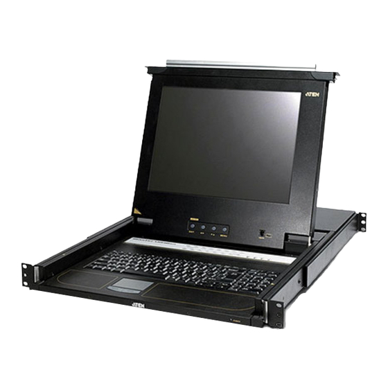
Page 14: Cl-1208 / Cl-1216Bl Front View
CL-1208 / CL-1216 User Manual CL-1208 / CL-1216BL Front View 4 & 5 4 & 5 10 & 11 10 & 11 2005-05-03... - Page 15 Upgrade that transfers the firmware upgrade data from the Section administrator’s computer to the CL-1208 / CL-1216 plugs into this RJ-11 connector. w Firmware Upgrade Switch: During normal operation this switch should be in the NORMAL position. (See p. 49 for firmware upgrading details.)
-
Page 16: Cl-1208 / Cl-1216 Rear View
CL-1208 / CL-1216 User Manual CL-1208 / CL-1216 Rear View 2005-04-26... - Page 17 Power Switch This is a standard rocker switch that powers the unit On and Off. External For flexibility and convenience, the CL-1208 / CL-1216 Console supports an independent, external, KVM console. The Section external console’s keyboard, monitor, and mouse cables plug in here.
- Page 18 CL-1208 / CL-1216 User Manual Notes: 2005-04-26...
-
Page 19: Installation
Before you Begin 1. Make sure that power to all the devices you will be connecting up have been turned off. You must unplug the power cords of any computers that have the Keyboard Power On function. Otherwise, the switch will receive power from the computer. 2. - Page 20 CL-1208 / CL-1216 User Manual 4. Power on the switch. 5. After the switch is powered on, power on the computers. 2005-04-26...
-
Page 21: Daisy Chaining
CL-1216, except that they come in standard housings without the built in Slideaway™ console. As many as 256 (CL-1208) or 512 (CL-1216) computers can be controlled from the unit’s integrated Slideaway™ console in a complete installation. Tables showing the relation between the number of computers and the number of Master View units needed to control them are provided on p. - Page 22 CL-1208 / CL-1216 User Manual 5. Power up the installation according to the following procedure: a) Power on the First Station (CL-1208 or CL-1216). Wait a few seconds for the unit to ascertain its Station ID. b) Plug in the power adapters for each daisy chained Station on the installation in turn (Second Station, then Third Station, etc.).
- Page 23 Installation CL-1216 ACS-1216A ACS-1216A 2005-04-26...
- Page 24 CL-1208 / CL-1216 User Manual Notes: 2005-04-26...
-
Page 25: Basic Operation
Opening the Console The CL-1208 / CL-1216’s console is located under the top cover. To access the console, slide the console module out and raise the cover. Note: As a safety precaution, to keep the console from accidentally sliding out, the console is locked into the In position. Before you can pull the console module out, you must release it by pushing the catches on the unit’s front panel toward the center of the switch. -
Page 26: Closing The Console
CL-1208 / CL-1216 User Manual Closing the Console To slide the console module back in, close the cover and do the following: 1. Pull the safety catches on the unit’s side rails toward you and push the module in until it stops. -
Page 27: Lcd Osd Configuration
LCD OSD Configuration The LCD Buttons The LCD OSD allows you to set up and configure the LCD display. Four buttons are used to perform the configuration, as described in the table, below: Button M When you have not entered the LCD OSD Menu function, pressing MENU this button invokes the Menu function, and brings up the Main Menu. -
Page 28: The Adjustment Settings
CL-1208 / CL-1216 User Manual The Adjustment Settings An explanation of the LCD OSD adjustment settings is given in the table below: Setting Brightness Adjusts the background black level of the screen image. Contrast Adjusts the foreground white level of the screen image. -
Page 29: Port Selection
Press buttons 1 & 2 simultaneously for two seconds to perform a keyboard and mouse reset. Press buttons 7 & 8 (CL-1208) or 15 & 16 (CL-1216) simultaneously for two seconds to invoke Auto Scan Mode (see p. 43). Basic Operation... -
Page 30: Hot Plugging
CL-1208 / CL-1216 User Manual Hot Plugging The CL-1208 / CL-1216 supports hot plugging - components can be removed and added back into the installation by unplugging their cables from the ports without the need to shut the unit down. In order for hot... -
Page 31: Powering Off And Restarting
Powering Off and Restarting If it becomes necessary to Power Off one of the ACS- 1208A / ACS-1216A units, unplug the power adapter cable from the rear panel. Before starting it back up you must do the following: 1. Shut down all the computers that are attached to it. Note: You must unplug the power cords of any computers that have the Keyboard Power On function. -
Page 32: Port Id Numbering
The Station Number - is a two digit number which reflects the switch’s position in the daisy chain sequence. Note: 1. The first station CL-1208 / CL-1216 has a Station Number of 01. The first daisy chained unit (ACS-1208A / ACS-1216A) has a Station Number of 02, etc. -
Page 33: Osd Operation
OSD Overview The On Screen Display (OSD) is a menu driven method to handle computer control and switching operations. All procedures start from the OSD Main Screen. To pop up the Main Screen, tap the [Scroll Lock] key twice. Note: You can optionally change the Hotkey to the Ctrl key, in which case you would tap [Ctrl] twice (see OSD Hotkey, p. - Page 34 CL-1208 / CL-1216 User Manual When you invoke the OSD, a screen similar to the one below appears: F1:GOTO F3:SET F2:LIST F4:ADM ADMINISTRATOR LIST:ALL SN PN Note: 1. The diagram depicts the Administrator’s Main Screen. The User Main Screen does not show the F4 and F6 functions, since these are reserved for the Administrator and can’t be accessed by...
-
Page 35: Osd Navigation
OSD Navigation To dismiss the menu, and deactivate the OSD, Click the X at the upper right corner of the OSD Window; or press [Esc]. To Logout, Click F8 or the symbol at the top of the Main Screen, or press [F8]. -
Page 36: Osd Functions
CL-1208 / CL-1216 User Manual OSD Functions OSD functions are used to configure and control the OSD. For example, you can: rapidly switch to any port; scan selected ports only; limit the list you wish to view; designate a port as a Quick View Port; create or edit a port name;... -
Page 37: F2 List
F2 LIST: This function lets you broaden or narrow the scope of which ports the OSD displays (lists) on the Main Screen. Many of the OSD functions only operate on the computers currently selected for Listing on the Main Screen with this function. -
Page 38: F3 Set
CL-1208 / CL-1216 User Manual F3 SET: This function allows the Administrator and each User to set up their own, individual, working environment. A separate profile for each is stored by the OSD and is activated according to the Username provided during Login. - Page 39 (F3 SET: continued) Setting PORT ID Selects how the Port ID is displayed: the Port Number alone DISPLAY (PORT NUMBER); the Port Name alone (PORT NAME); or the MODE Port Number plus the Port Name (PORT NUMBER + PORT NAME). The default is PORT NUMBER + PORT NAME). SCAN Determines how long the focus dwells on each port as it cycles DURATION...
-
Page 40: F4 Adm
CL-1208 / CL-1216 User Manual F4 ADM: F4 is an Administrator only function. It allows the Administrator to configure and control the overall operation of the OSD. To change a setting Double Click it; or use the Up and Down Arrow Keys to move the highlight bar to it then press [Enter]. - Page 41 (F4 ADM: continued) Setting EDIT PORT To help remember which computer is attached to a particular port, NAMES every port can be given a name. This function allows the Administrator to create, modify, or delete port names. To Edit a port name: 1.
- Page 42 CL-1208 / CL-1216 User Manual (F4 ADM: continued) Setting SET QUICK This function lets the Administrator select which Ports to include VIEW PORTS as Quick View ports. w To select/deselect a port as a Quick View Port, use the Navigation Keys to move the highlight bar to it, then press the [Spacebar].
- Page 43 Set Quick View Ports, etc.), for all of the computers affected by the change, have to be manually redone. FIRMWARE In order to upgrade the CL-1208 / CL-1216’s firmware (see UPGRADE Chapter 31), you must first enable Firmware Upgrade Mode with this setting.
-
Page 44: F5 Skp
CL-1208 / CL-1216 User Manual F5 SKP: This function enables you to easily skip backward or forward - switching the KVM focus from the currently active computer port to the previous or next available one. The selection of computers to be available for Skip Mode switching is made with the Scan/Skip Mode setting under the F3 SET function (see p. -
Page 45: F6 Brc
F6 BRC: F6 is an Administrator only function. When this function is in effect, commands sent from the console are broadcast to all available computers on the installation. This function is particularly useful for operations that need to be performed on multiple computers, such as performing a system wide shutdown, installing or upgrading software, etc. -
Page 46: F7 Scan
CL-1208 / CL-1216 User Manual F7 SCAN: This function automatically switches among the available computers at regular intervals so that you can monitor their activity without having to take the trouble of switching manually. The selection of computers to be included for Auto Scanning is made with the Scan/Skip Mode setting under the F3 SET function (see p. -
Page 47: F8 Lout
F8 LOUT: Clicking the F8 field or, or pressing [F8] logs you out of the OSD, and blanks the Console screen. This is different from simply deactivating the OSD when you are at the Main Screen by pressing [Esc]. With this function you must log in all over again to regain access to the OSD, whereas with [Esc], all you have to do to reenter the OSD is tap the OSD Hotkey. - Page 48 CL-1208 / CL-1216 User Manual Notes: 2005-04-26...
-
Page 49: Hotkey Operation
Hotkey Port Access Hotkey Port Access allows you to provide the KVM focus to any computer on your installation directly from the keyboard. The CL-1208 / CL-1216 provides three hotkey port access features: Selecting the Active Port Auto Scanning Skip Mode Switching... -
Page 50: Selecting The Active Port
CL-1208 / CL-1216 User Manual When Hotkey Mode is active: The Caps Lock, and Scroll Lock LEDs flash in succession to indicate so. They stop flashing and revert to normal status when you exit HKM. A Command Line appears on the monitor screen. The command line prompt is the word Hotkey: in yellow text on a blue background, and displays the subsequent Hotkey information that you key in. -
Page 51: Auto Scanning
Auto Scanning Auto Scan automatically switches among all the active CPU Ports that are accessible to the currently logged on User at regular intervals, allowing automatic monitoring of computer activity. (See Scan/Skip Mode of the OSD F3 SET function, p. 31 for information regarding accessible ports.) Setting the Scan Interval: The amount of time Auto Scan dwells on each port is set with the Scan Duration setting of the OSD F3 SET function (see p. - Page 52 CL-1208 / CL-1216 User Manual Invoking Auto Scan: To start Auto Scanning, key in the following Hotkey combination: 1. Invoke HKM (see p. 41). 2. Press [A]. When you press A, you automatically exit HKM; enter Auto Scan Mode; and Auto Scanning begins.
-
Page 53: Skip Mode
Skip Mode This feature allows you to switch between computers in order to monitor them manually. You can dwell on a particular port for as long or as little as you like - as opposed to Auto Scanning, which automatically switches after a fixed interval. -
Page 54: Hotkey Beeper Control
CL-1208 / CL-1216 User Manual Hotkey Beeper Control The Beeper can be Hotkey toggled On and Off (see Activate Beeper, p. 33). To toggle the Beeper, key in the following Hotkey combination: 1. Invoke HKM (see p. 41). 2. Press [B] After you press B, the Beeper toggles On or Off. -
Page 55: Hotkey Summary Table
Hotkey Summary Table [Num Lock] + [-] [Port ID] [Enter] Switches access to the computer that corresponds to that Port ID. [T] [n] [Enter] Sets the Auto Scan interval to n seconds - where n is a number from 1 - 255. Invokes Auto Scan Mode. - Page 56 CL-1208 / CL-1216 User Manual Notes: 2005-04-26...
-
Page 57: The Firmware Upgrade Utility
Chapter 6. The Firmware Upgrade Utility The Windows-based Firmware Upgrade Utility (FWUpgrade.exe) provides a smooth, automated process for upgrading the KVM switch’s firmware. The Utility comes as part of a Firmware Upgrade Package that is specific for each device. New firmware upgrade packages are posted on our web site as new firmware revisions become available. -
Page 58: Preparation
CL-1208 / CL-1216 User Manual Preparation To prepare for the firmware upgrade, do the following: 1. From a computer that is not part of your KVM installation go to our Internet support site and choose the model name that relates to your device to get a list of available Firmware Upgrade Packages. -
Page 59: Starting The Upgrade
Starting the Upgrade To upgrade your firmware: 1. Run the downloaded Firmware Upgrade Package file - either by double clicking the file icon, or by opening a command line and entering the full path to it. The Firmware Upgrade Utility Welcome screen appears: Note: The screens shown in this section are for reference only. - Page 60 CL-1208 / CL-1216 User Manual 3. Click Next to continue. The Firmware Upgrade Utility main screen appears. The devices capable of being upgraded are listed in the Device List panel: 4. As you select devices, a detailed description of each appears in the Device Description panel.
- Page 61 The Firmware Upgrade Utility 5. After you have made your device selection(s), Click Next to perform the upgrade. If you enabled Check Firmware Version, the Utility compares the device’s firmware level with that of the upgrade files. If it finds that the device’s version is higher than the upgrade version, it brings up a dialog box informing you of the situation and gives you the option to Continue or Cancel.
-
Page 62: Upgrade Succeeded
CL-1208 / CL-1216 User Manual Upgrade Succeeded After the upgrade has completed, a screen appears to inform you that the procedure was successful: Click Finish to close the Firmware Upgrade Utility. Upgrade Failed If the Upgrade Succeeded screen doesn’t appear, it means that the upgrade failed to complete successfully. -
Page 63: Firmware Upgrade Recovery
Firmware Upgrade Recovery There are basically three conditions that call for firmware upgrade recovery: When you invoke Firmware Upgrade Mode (see p. 50), but decide not to proceed with the upgrade. When the Mainboard firmware upgrade fails. When the I/O firmware upgrade fails. To perform a firmware upgrade recovery, do the following: 1. - Page 64 CL-1208 / CL-1216 User Manual Notes: 2005-04-26...
-
Page 65: Appendix
Connection Tables The following tables indicate the relationship between the number of Master View units and the number of computers that they control on a daisy chained installation: CL-1208 + ACS-1208A Computers Computers 1 - 8 65 - 72 9 - 16... -
Page 66: Osd Factory Default Settings
CL-1208 / CL-1216 User Manual OSD Factory Default Settings The factory default settings are as follows: Setting OSD Hotkey [Scroll Lock] [Scroll Lock] Port ID Display Position Upper Left Corner Port ID Display Duration 3 Seconds Port ID Display Mode... -
Page 67: Clear Login Information
Clear Login Information If you are unable to perform an Administrator login (because the Username and Password information has become corrupted, or you have forgotten it, for example), you can clear the login information with the following procedure: 1. Power off the switch and remove the top cover from the unit chassis. 2. -
Page 68: Rack Mounting
Rack Mounting Standard Rack Mounting A standard rack mounting kit is provided with your CL-1208 / CL-1216. The kit enables the switch to be mounted in rack with a depth of 45 - 85 cm. To rack mount the switch, do the following: 1. -
Page 69: Optional Rack Mounting
Optional Rack Mounting For convenience and flexibility, three optional rack mounting kits are available: 1) a long bracket (68.0 - 110.0 cm) standard rack mounting kit; 2) a short bracket (41.5 - 70cm) Easy-Installation rack mount kit; and a long bracket (68.0 - 105.0cm) Easy-Installation rack mount kit. - Page 70 CL-1208 / CL-1216 User Manual 2. Attach the left and right easy-installation mounting rails to the inside of the rack. The flange that supports the switch will be to the inside. Rear Flange Slide Bar LEFT Support RAIL Flange RIGHT RAIL a) Screw the front flanges to the rack first.
- Page 71 3. Slide the switch onto the support flanges and secure it to the mounting rails at the front. 4. Slide the rear attachment sliding bracket along the slide bar until it contacts the rear of the switch, then screw it to the rear of the switch. Appendix 2005-04-26...
-
Page 72: Specifications
CL-1208 / CL-1216 User Manual Specifications Function CL-1208 Computer Direct Connections 256 (via Daisy Chain) Port Selection Push button switches: OSD (On Screen Display); Hotkeys LEDs On Line 8 (Orange) Selected 8 (Green) Power 1 (Blue) Lock 1 x Num Lock (Green) -
Page 73: Troubleshooting
The distance between the external console and the on the external monitor. CL-1208 / CL-1216 is too great. The maximum cable distance should not exceed 20m and, in some cases, may need to be shorter. Replace the VGA cable with one of an appropriately short length.