
Related Manuals for MTD PRO MMZ 2554


Summary of Contents for MTD PRO MMZ 2554
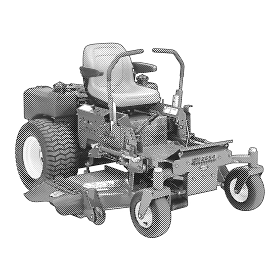
- Page 1 ® MMZ 2254, 2554, 2560 25 Horsepower Hydrostatic Zero-Turn Commercial Riding Mower OPERATOR’S AND SERVICE MANUAL...
-
Page 2: Table Of Contents
TABLE OF CONTENTS Foreword ............3 Safety Precautions . -
Page 3: Foreword
FORWARD The MMZ Gasoline Powered Hydraulic Driven Rotary Mowers were developed to provide superb maneuverability, mid-mount cutting capability for professional land- scapers, commercial lawn service companies, professional turf managers and golf course superintendents. The machine incorporates many safety features that should be studied by all operators and maintenance personnel before use. -
Page 4: Safety Precautions
SAFETY PRECAUTIONS A. General Read this Operator’s Manual before starting the mower. Study the controls and learn the proper sequence of operation. Do not allow anyone to operate or maintain this machine who has not read this manual. Never permit children to operate this machine. -
Page 5: When Mowing
When filling the fuel tank, stop when the fuel reaches one inch from the top. This space is necessary for tank expansion. Do not overfill. Wipe up any spilled fuel. C. When Mowing Keep adults, children and pets away from the area to be mowed. When operating this mower in the forward direction, DO NOT allow the steering levers to return to the neutral position on their own. -
Page 6: Specifications
brake; shutting off the engine and taking the key from the ignition switch. 14. Never walk or stand on the discharge side of a mower with the engine running. Turn off the blade clutch switch if another person approaches while you are operating the mower. 15. -
Page 7: Operating Instructions
OPERATING INSTRUCTIONS Figure. 1 Electric Blade Clutch Ignition Switch A. Controls Engine Ignition and Start Switch: (See Figure 1.) Located on the instrument housing below the right side of the operator’s seat. When the key is inserted and turned clockwise, 45 degrees, the ignition circuit is closed. - Page 8 amount, one traction wheel will turn in reverse and the mower will turn within its own length. In order to start the engine, both steering levers must be opened out to the side in the neutral position; the parking brake must be engaged;...
-
Page 9: Initial Adjustments
the deck lift handle and move it outward. This allows the handle to move forward, lowering the deck to the cutting position. Fuel Shutoff Valve: (See Figure 4.) Located on top of the fuel tank. When turned in a clockwise direction until it stops, it will shut off the flow of fuel to the engine. - Page 10 oil through the fill tube using a funnel to bring it up to the top of the operating range. Note: Gasoline Engine: Use SAE 10W30 or SAE 10W40 engine oil, rated for ser- vice SJ. Hydraulic Oil: (Filled at the factory before shipment.) The hydraulic oil tank is located beneath the operator’s seat.
-
Page 11: Break-In And Operation
If the dimension at the front of the mowing deck is 1/8"-1/ 4" lower than the dimension at the rear of the deck on each side of the mower, do not adjust. If not, you will need to adjust the Deck Lift Spring Assist (See Figure 5). - Page 12 Push the throttle control to a position a third of the way between slow and fast. Insert the key in the ignition and start switch and turn the switch to “On”. Gasoline Engine: If the engine is cold, push the choke to the on position.
-
Page 13: Maintenance And Service
To turn, pull the lever back on the side to which you want to turn. The farther back you pull the lever, the faster and more sharply you will turn. Initially, you will have to be care- ful to avoid turning to fast and too far. After you have mastered operating the mower, use the transport lever to lower the mowing deck to the cutting posi- tion and pull on the electric blade clutch switch to start the... - Page 14 Figure. 6 Height of Cut Clevis Pin Remove six linchpins (See Fig. 6) (4) from the deck and (2) from the front of the mower. Remove the linchpins on the left and right rear side of the cutter deck (2); remove the linchpins on the left and right front side of the cutter deck (2);...
- Page 15 Never mow with dull blades! Blades that are bent should be replaced! The cutting blades are sharp and can cause severe injury. Wrap the cutting surface of the blade with a rag to avoid injury. Set the parking brake. Clean any debris from the blades. Keep blades sharp and free of build up at all times.
-
Page 16: Hydraulic Oil
Changing the Spindle Assembly Jack up the front of the mowing deck about one foot and block it in that posi- tion. Make sure the blade clutch is disen- gaged. Remove the deck cover. Remove the drive belts. (See 3. Chang- ing Blade Drive Belts.) Remove the cutter... -
Page 17: Electrical System
Remove the hydraulic fill cap and check the level. The cor- rect level is up to the lowest hole of the oil tank fill neck. Pour hydraulic oil into the reservoir up to the lowest hole in the oil tank fill neck, if necessary. Draining Hydraulic Oil Used hydraulic oil must be disposed of properly. - Page 18 ends clean with a wire brush and make sure the connections are tight. Coat the terminals with petroleum jelly to prevent corrosion. Battery Storage: When storing the MMZ for long periods of time the following guidelines should be taken. Disconnect the battery cables from the terminals and remove the battery.
- Page 19 Jump Starting Failure to use this starting procedure can cause sparking, and the gases in the battery to explode. Attach the end of the red jumper cable to the Positive termi- nal (+) of the charged battery. Attach the other end of the red jumper cable to the Positive terminal (+) of the low charge battery.
- Page 20 the parking brake switch must be repositioned or perhaps replaced. If the engine does not start, engage the parking brake and start the engine. Swing one steering lever up to the operating position and the engine should stop. If the engine does not stop, the parking brake switch must be repositioned or replaced.
-
Page 21: Tires
the blade clutch switch is turned on.This electric clutch is a fairly trouble free device. If a problem develops and the blades do not turn, first check the 7.5 amp fuse in the yel- low, 16-gauge wire between terminal “L” (for the Gasoline Engine) on the ignition switch and the hour meter and then investigate the wiring harness and the connections to the seat switch, the blade clutch switch and the electric blade... -
Page 22: Brakes
two spacer sleeves will drop free. Slip the axle assembly through one side of the caster yoke, through a spacer sleeve, a spare wheel, the other spacer sleeve and finally through the other side of the caster yoke. Then tighten the locknut on the end of the axle assembly. -
Page 23: Hydraulic System
Note: If you wish to move the mower by pushing, you must release the dynamic brak- ing. Locate the levers at the rear of the mower. Pull both levers out and lock in position. After pushing the mower to the desired location, return both levers to the operating position (See photo at right). - Page 24 rest of the hydraulic system. Fill the replacement filter with a good grade of 20W-50 oil and lubricate the sealing surface. Screw the filter onto the filter base until it seats and then another one-half turn to seal. Note: Always wipe off the hydraulic tank fill cap and the area around it before removing the cap to prevent dirt from contaminating the oil.
- Page 25 opened out to the neutral position. If the MMZ begins to creep, adjust the Steering Levers. If the mower creeps, first determine whether it creeps to the right or left side and which direction the mower moves — to the front or the rear.
-
Page 26: Storage
G. Storage General: If your mower will not be in service for a few months, it should be stored in a dry location that is not subject to drastic changes in temperature. Before storing, the following maintenance procedures should be performed. Clean the mower. -
Page 27: Maintenance Schedule
Push the mower outdoors and start the engine. Let the engine idle until it has warmed up completely (4 to 5 min- utes). MAINTENANCE SCHEDULE A. Daily Checks Before starting engine: Check the fuel level. Check the engine oil level. Check the hydraulic oil level. - Page 28 Change the engine oil filter. (Every 50 hours under heavy duty operation.) Check the engine spark plugs. E. Yearly Checks Check the oil in the hydraulic reservoir. * Perform maintenance more frequently under dusty conditions. Apply a few drops of SAE 20W-50 engine oil or use a spray lubricant.
- Page 29 LUBRICATION CHART Use a grease-gun filled with NO. 2 Multipurpose Lithium Base Grease Number of Grease Fittings Description EVERY 25 HOURS Blade Spindle Bearings WEEKLY Front Caster Wheels Front Caster Wheel Spindles Mowing Deck Pivots Deck Take-Up Idler Pivots Axle Pivot Steering Lever Pivots Hydro Take-up Idler Pivot Park Brake Pivot...
-
Page 30: Wiring Diagram
WIRING DIAGRAM... - Page 32 1. What Is Covered By This Warranty. This limited warranty covers any defect in materials or workman- ship in your MTD Pro equipment for two year from the date of purchase for the first user purchaser. MTD Pro will replace or repair any part or parts without charge through your authorized MTD Pro dealer. Bat- teries, belts and tires will be covered for a period of ninety (90) days from date of purchase.