Table of Contents
Advertisement
DVD RECORDER
DVR-533H-S
DVR-633H-S
DVR-531H-S
THIS MANUAL IS APPLICABLE TO THE FOLLOWING MODEL(S) AND TYPE(S).
Model
Type
DVR-533H-S
KUXV
DVR-533H-S
KCXV
DVR-633H-S
KUXV/CA
DVR-531H-S
KUXV/CA
DVR-531H-S
KCXV
÷
When servicing this model, some service procedures may reset the customer settings
to the factory default settings. Make sure to explain this to the customer.
An HDD (Hard Disc Drive) is mounted in this product.
The HDD is a precision instrument very vulnerable to shock and electrostatic charges. Please read
"7.3 Cautions on Handling the HDD" in this manual and exercise sufficient caution when handling the
HDD itself, as well as the product with the HDD built in.
When an HDD becomes defective and inoperable, restoration of the user's data recorded on the HDD,
or copying of the user's recorded data to other media (such as a new HDD) is totally impossible.
Before servicing, OBTAIN THE USER'S PRIOR CONSENT to that effect.
The user must be made aware that all recorded data are deleted if the HDD is intialized.
For details, refer to "Important Check Points for Good Servicing" .
PIONEER CORPORATION
PIONEER ELECTRONICS (USA) INC. P.O. Box 1760, Long Beach, CA 90801-1760, U.S.A.
PIONEER EUROPE NV Haven 1087, Keetberglaan 1, 9120 Melsele, Belgium
PIONEER ELECTRONICS ASIACENTRE PTE. LTD. 253 Alexandra Road, #04-01, Singapore 159936
PIONEER CORPORATION 2005
STANDBY / ON
Power Requirement
AC120V
AC120V
AC120V
AC120V
AC120V
4-1, Meguro 1-chome, Meguro-ku, Tokyo 153-8654, Japan
HDD/DVD
TOP MENU
MENU
HOME
ENTER
ONE TOUCH
PULL - OPEN
COPY
MENU
RETURN
ì
REC
DVR-533H-S
Region No.
1
1
1
1
1
T-ZZV JUNE 2005 printed in Japan
ORDER NO.
RRV3173
Serial No.
Please confirm 3rd & 4th
alphabetical letters.
&&DL######$$
&&DL######$$
&&DL######$$
&&DL######$$
&&DL######$$
Advertisement
Table of Contents

Related Manuals for Pioneer DVR-533H-S


Summary of Contents for Pioneer DVR-533H-S
-
Page 1: Dvd Recorder
PIONEER CORPORATION 4-1, Meguro 1-chome, Meguro-ku, Tokyo 153-8654, Japan PIONEER ELECTRONICS (USA) INC. P.O. Box 1760, Long Beach, CA 90801-1760, U.S.A. PIONEER EUROPE NV Haven 1087, Keetberglaan 1, 9120 Melsele, Belgium PIONEER ELECTRONICS ASIACENTRE PTE. LTD. 253 Alexandra Road, #04-01, Singapore 159936... -
Page 2: Safety Information
For the latest information, always consult the current PIONEER Service Manual. A subscription to, or additional copies Also test with plug reversed of, PIONEER Service Manual may be obtained at a (Using AC adapter Earth nominal charge from PIONEER. plug as required) - Page 3 LABEL CHECK IMPORTANT LASER DIODE CHARACTERISTICS THIS PIONEER APPARATUS CONTAINS MAXIMUM OUTPUT POWER: 100 mW LASER OF CLASS 1. WAVELENGTH: 654 - 662 nm SERVICING OPERATION OF THE APPARATUS LASER DIODE CHARACTERISTICS SHOULD BE DONE BY A SPECIALLY MAXIMUM OUTPUT POWER: 5 mW INSTRUCTED PERSON.
- Page 4 To protect products from damages or failures during transit, the shipping mode should be set or the shipping screws should be installed before shipment. Please be sure to follow this method especially if it is specified in this manual. DVR-533H-S...
-
Page 5: Table Of Contents
7.1.5 SERVICE MODE ..........................79 7.1.6 DV SERVICE MODE...........................93 7.1.7 EPG SERVICE MODE........................96 7.1.8 AGING MODE ............................99 7.1.9 HDD CHECK MODE.........................101 7.1.10 SETUP SEQUENCE........................107 7.1.11 DISASSEMBLY..........................108 7.2 IC ................................114 7.3 CAUTIONS ON HANDLING THE HDD....................125 7.4 DISC/CONTENT FORMAT ........................127 8. PANEL FACILITIES ............................129 DVR-533H-S... -
Page 6: Specifications
Programs ......1 month/32 programs DVR-533H-S ....... . .43 W Clock . - Page 7 REV SCAN PLAY FWD SCAN PAUSE STOP • Dry cell batteries ×2 BACK SKIP CASE PREV NEXT STEP/SLOW SELECTION (AA/R6P) STOP REC REC MODE TIMER REC ì • IR Blaster ×1 TV CONTROL INPUT CHANNEL VOLUME SELECT (VDX1010) DVD RECORDER DVR-533H-S...
-
Page 8: Exploded Views And Parts List
For the applying amount of lubricants or glue, follow the instructions in this manual. (In the case of no amount instructions, apply as you think it appropriate.) 2.1 PACKING KCXV type only DVR-533H-S... - Page 9 Dual Layer IM (French) See Contrast table (2) Quick Start Guide (English) VRG1010 Quick Start Guide (French) See Contrast table (2) (2) CONTRAST TABLE DVR-533H-S/KUXV, KCXV, DVR-633H-S/KUXV/CA, DVR-531H-S/KCXV and KUXV/CA are constructed the same except for the following: DVR-533H-S DVR-533H-S DVR-633H-S DVR-531H-S DVR-531H-S Mark No.
-
Page 10: Exterior Section
2.2 EXTERIOR SECTION Lithium Battery 49 47 (CR2032) Cleaning paper GED-008 DVR-533H-S, DVR-633H-S only Refer to "2.3 FRONT PANEL SECTION". DVR-533H-S... - Page 11 Bonnet Case S VXX3039 Rear Panel See Contrast table (2) NSP 30 Base Chassis VNB1052 (2) CONTRAST TABLE DVR-533H-S/KUXV, KCXV, DVR-633H-S/KUXV/CA, DVR-531H-S/KCXV and KUXV/CA are constructed the same except for the following: DVR-533H-S DVR-533H-S DVR-633H-S DVR-531H-S DVR-531H-S Mark No. Symbol and Description...
-
Page 12: Front Panel Section
2.3 FRONT PANEL SECTION DVR-633H-S 11 (1/4) only 11 (2/4) 11 (4/4) DVR-531H-S only DVR-633H-S only 11 (3/4) DVR-633H-S only DVR-533H-S... - Page 13 See Contrast table (2) REC Plate A See Contrast table (2) Sensor-matic Seal See Contrast table (2) Screw BPZ30P080FTC (2) CONTRAST TABLE DVR-533H-S/KUXV, KCXV, DVR-633H-S/KUXV/CA, DVR-531H-S/KCXV and KUXV/CA are constructed the same except for the following: DVR-533H-S DVR-533H-S DVR-633H-S DVR-531H-S DVR-531H-S Mark No.
-
Page 14: Block Diagram And Schematic Diagram
IC202 SDRAM 16Mbit CN101 IC203 FLASH IC1301 ATA SDRAM (45P) IC201 512Mbit UPD63641GM SPDL MOTOR Pickup DRIVE Flash 64Mbit IC1102 PB DVD/CD RF IC IC101 PICKUP UPC3340GC CN501 ASSY (12P) Driver LOADING MOTOR DRIVE ASSY(R9R) CN502 IC501 STEPPIONG BD7997FS MOTOR DVR-533H-S... - Page 15 L OUT D/A Conv. CN401 CN3001 IC3251-1/2 MAIN ASSY JA501 UPC4570G2 SPDIF OPTICAL Tuner U-com AC-3/PCM (27P) (27P) DIGITAL IC301 PT6315 AUDIO FLJB ASSY CN101(2/2) FL Driver (27P) V301 RSWB ASSY MSL : Music Server Lch CN301(2/2) (27P) PSWB ASSY DVR-533H-S...
-
Page 16: Main Assy
3.1.2 MAIN ASSY SERIAL Blastor IC3401 IC1201, 1221 IC1301 DDR SDRAM DDR SDRAM 128M x 2 512M CN2201 CN3001 CN3801 CN1901 DVR-533H-S... - Page 17 DVR-533H-S...
-
Page 18: Overall Wiring Diagram
3.2 OVERALL WIRING DIAGRAM AC IN VKN2012 1/2, POWER SUPPLY JACB ASSY UNIT (VWV2111:DVR-533H/633H) (VWR1391) (VWV2112:DVR-531H) VKN2011 1/5- MAIN ASSY (VXX2993:DVR-533H/633H) (VXX2994:DVR-531H) DRIVE ASSY R9R (VXX2987) DVR-533H-S... - Page 19 ÷ The > mark found on some component parts indicates the importance of the safety factor of the part. Therefore, when replacing, be sure to use parts of identical designation. ÷ : The power supply is shown with the marked box. DVR-533H-S...
-
Page 20: Tunb Assy
3.3 TUNB ASSY TUNB ASSY (VXX3024) U101 VXF1059 <U/V TUNER BLOCK> 5 6 7 8 9 10 13 14 15 16 R105 (2125) R104 Q102 2SA1576A(QR)-TLB R120 DVR-533H-S... - Page 21 V+31V KN101 V+5TU VNE1948- SW+6V CN101 XKP3079- J_CLOCK UVOUT UVOUT SW+6V V+5TU V+31V HN1A01FU B C2 DVR-533H-S...
-
Page 22: Jacb(1/2) And Fljb Assys
SELECT C153 C151 ROUT 2-D1 10/50 GND TunerR LOUT 10/50 ROUT TunerL 2-B1 2-D1 C152 10/50 C154 LOUT 2-B1 FILTER 10/50 R188 C157 R193 10/50 C158 R192 10/50 R200 IC103 BD3823FV-TBB C159 R197 10/50 C160 R198 10/50 JA103 VKB1183- DVR-533H-S... - Page 23 (162-1076-02) D312 D310 D311 Q307 GND2 2SC5712-TLB D305 C320 R316 R329 GND2 1SS355-TRB 0.022 /MONO YB (2125) D310–312 : DF3A5.6FU-TLB Q306 Q308 GND2 GND1 R327 GND2 UDZS2R4(B)-TRB D303 2SC4081(QR)-TLB D306 2SA1576A(QR)-TLB RF101L2S-TRB D302 JA302 UDZS13(B)-TRB VKB1189- GND2 GND1 GND2 DVR-533H-S...
-
Page 24: Jacb Assy(2/2)
C443 C-IN2 C.SYNCOUT C444 V+6TU C450 C-IN3 V-DET-IN V+31V C456 C452 C-OUT V+31V C453 D404 D405 D406 470/6.3 Y-OUT SELV1 INSEL1 LPF-CTL C445 Y-IN1 SELV2 INSEL2 C446 Y-IN2 TEST MODE SELV3 INSEL3 C447 SWSTBY Y-IN3 STBY_H D407 D408 D409 DVR-533H-S... - Page 25 VCH1241- -T (47/16) Q514 R559 HN1C03FU(AB)-T 3.9K R528 GNDA R560 GNDA Q514 R561 GNDA HN1C03FU(AB)-T 3.9K R529 GNDA C523 R530 R532 C550 VCH1241- -T R563 (47/16) R533 R564 Q515 HN1C03FU(AB)-T 3.9K R566 GNDA R534 GNDA R567 Q515 HN1C03FU(AB)-T 3.9K GNDA DVR-533H-S...
-
Page 26: Dvjb Assy
3.6 DVJB ASSY DVJB ASSY (VWG2523) CN601 VKN2013- -TFB USB_DM2 USB_DP2 JA601 USB+5V VKN1800- -TLB USB+5V TPAP TPAN TPAP DV Input TPBP TPBN TPAN TPBP TPBN GND4 GND4 DVR-533H-S... -
Page 27: Atab Assy
3.7 ATAB ASSY ATAB ASSY (VWV2123)(for HDD) CN12 CN11 VKN2009- -TBB VKN1816- RESET# DD10 DD11 DD12 DD13 DD14 DD15 (KEYPIN) DMARQ DIOW# DIOR# IORDY CSEL DMACK# INTRQ RESERVED PDIAG# CS0# CS1# DASP# GND3 GND3 DVR-533H-S... -
Page 28: Pswb And Rswb Assys
3.8 PSWB and RSWB ASSYS PSWB ASSY (VWG2524) CN1101 TP116 TP117 S3B-PH-K-S KEY1_1 Switches KEY2_1 S1212:PAUSE S1213:STOP S1405 S1212 S1405:PLAY PLAY PAUSE GND2 2.85V 2.85V S1406:POWER VSG1024- -T VSG1024- -T S1406 S1213 POWER STOP 3.58V 3.58V VSG1024- -T VSG1024- -T GND2 GND2 DVR-533H-S... - Page 29 VSG1024- -T S1404 TP119 TP121 LEFT 2.18V VSG1024- -T TP113 (HDD) TP112 (DVD) GND1 Q1203 Q1202 DTC124EUA-TLB DTC124EUA-TLB GND1 GND1 Switches S1201:MENU S1208:ONE TOUCH COPY S1202:RIGHT S1209:REC STOP S1203:UP S1210:REC S1204:ENTER S1211:RETURN S1205:DOWN S1401:HDD/DVD S1206:HOME MENU S1402:OPEN/CLOSE S1403:TOP MENU S1404:LEFT DVR-533H-S...
-
Page 30: Main Assy(1/5)
0.1(S) (AC22) R1501 R1502 REXT1 (AB21) 3.9KF 68(J) REXT2 R1504 (AC20) R1503 3.9KF GNDD V+3D R1064 10K(S) RAB4CQ560J-T 56*4 56*4 RAB4CQ560J-T 56*4 RAB4CQ560J-T 56*4 RAB4CQ560J-T 56*4 RAB4CQ560J-T 56*4 56*4 RAB4CQ560J-T RAB4CQ560J-T 56*4 RAB4CQ560J-T 56*4 RAB4CQ560J-T 56*4 RAB4CQ560J-T 56*4 RAB4CQ560J-T DVR-533H-S... - Page 31 (VD) (8M*16bit) : C Video Signal Route : Video Data Signal Route DEC/ENC GNDD CODEC (Cr) : Audio Signal Route (L ch) : Cr Video Signal Route (Cb) : Cb Video Signal Route (Yp) : Yp Video Signal Route DVR-533H-S...
-
Page 32: Main Assy(2/5)
C_OUT 2SA1576A(QR)-TLB CR_OUT (Yp) (Yp) GNDD 1-D3 GOUT Q2503 Yp_OUT 2SA1576A(QR)-TLB CVBSIN (Cb) 4-B1 (Cb) GNDD 1-D3 BOUT Q2504 Cb_OUT 2SA1576A(QR)-TLB (Cr) CCRIN (Cr) GNDD 4-B1 1-D3 ROUT Q2505 Cr_OUT 2SA1576A(QR)-TLB GNDD GNDD OUTPUT Level Adj. Analog Video INPUT DVR-533H-S... - Page 33 RESISTOR : 2 1 2 5 size RS1/10S– GNDD : 1 6 0 8 size RS1/16S– CAPACITOR : 2 1 2 5 size CKSQ**– : 1 6 0 8 size CCSR**– GNDD CKSR**– UMF21N-TLB E1 B1 E1 B1 C2 DVR-533H-S...
-
Page 34: Main Assy(3/5)
PCM1802DB1-TBB R ch R3109 RCHIN GNDD 2-B6 0(S) VINL MODE1 VINR MODE0 GNDD GNDD VREF1 FMT1 VREF2 FMT0 R3105 0(S) AGND SCKI GNDD PDWN GNDD BYPAS DGND R3107 10(S) ADATAI TEST DOUT R3104 10(S) BCKI LRCK R3106 10(S) LRCKI DVR-533H-S... - Page 35 DMACK# R3848 R3849 AT2INTRQ INTRQ 10K(S) 82(S) RESERVED R3850 AT2ADR1 33(S) PDIAG# AT2ADR0 R3851 AT2ADR2 33*4 AT2CS0 CS0# RAB4CQ330J-T AT2CS1 CS1# V+5D DASP# VKN1794- -TFB CN3802 (FROM CLK) GNDD R3113 Secondary ATA 0(S) 3-C3 to HD Drive R3114 0(S) DVR-533H-S...
-
Page 36: Main Assy(4/5)
C4206 REC656I0 CLK8(28.6M) DOUT(3) 1 YF REC656I1 CLK4(14.3M) DOUT(4) REC656I2 GCLP DOUT(5) REC656I3 DOUT(6) C4207 REC656I4 V+3AED DOUT(7) REC656I5 VDDI DOUT(8) REC656I6 VDDE DOUT(9) REC656I7 C4208 R4253 22*4 GNDD GNDD R4236 0(S) FROM PRISM2 C4278 N2I BUS XEDRST 3-C3 DVR-533H-S... - Page 37 : C Video Signal Route GNDD DIG 3.3V REG R4513 V+3R45 R4514 IC4507 V+3D (S-1170B33UC-OTD-TRB) STANDBY GNDD V+3R45 V+3D Side-B IC4509 V+5D PQ035ZN01ZPH-TLB IC4512 (1.2V) NJM2861F33-TLB V+1R2 BIAS V+3CG 1.2V REG GNDD GNDD REG protection Diode is RB501V-40-TRB. 3.3V REG(for CLKGEN) DVR-533H-S...
-
Page 38: Main Assy(5/5)
L5606 C5122 0(S) VTH1043- -T V+5USB SPD/BDB DVDD (R5616) R5127 R5128 1k(S) TP5106 FNSEL GNDD PHYLREC USB+5V 10k(S) X5101 LREQ R5131 R5137 VSS1206–A-T DGND 10k(S) USB+5V 0(S) (DSX530G****) GNDD D_3.3V USB_DP2 USB_DM2 USB_A GNDD CN601 GNDD Only DVR-531H types DVR-533H-S... - Page 39 CPU BUS V+3D GNDD V+3D INT1 R5713 10k(S) DVR-533H-S...
-
Page 40: Power Supply Unit
AGAINST RISK OF FIRE. REPLACE ONLY WITH SAME TYPE NO. 491.630PF002 FOR P301 MFD, BY LITTELFUSE INC. CAUTION : FOR CONTINUED PROTECTION AGAINST RISK OF FIRE. REPLACE ONLY WITH SAME TYPE NO. 49101.6PF002 FOR P401 and P402 MFD, BY LITTELFUSE INC. DVR-533H-S... - Page 41 To HDD CN9014 CN4501 DVR-533H-S...
-
Page 42: Wave Forms
V: 500mV/div. H: 10µsec/div. V: 500mV/div. H: 10µsec/div. V: 2V/div. H: 200µsec/div. IC401 - pin 29 (Y) IC501 - pin 28 (Y), C518 + side (Function : L1) (Function : PLAY) V: 500mV/div. H: 10µsec/div. V: 500mV/div. H: 10µsec/div. DVR-533H-S... - Page 43 V: 1V/div. H: 20nsec/div. V: 1V/div. H: 20nsec/div. CN2201 - pin 18 (Cr/RMtoT) Foot of R3305 (VCO_18M) Foot of R3106 (AD_LRCKI) (State : Stopped) (State : Stopped) (State : Stopped) V: 0.5V/div. H: 10µsec/div. V: 1V/div. H: 20nsec/div. V: 1V/div. H: 10µsec/div. DVR-533H-S...
- Page 44 Foot of C4290 (CVBSIN) (State : Stopped) V: 0.5V/div. H: 10µsec/div. V: 1V/div. H: 5µsec/div. V: 1V/div. H: 200nsec/div. IC3202 - pin 7 (LCHOUT) Foot of C4278 (CCRIN) (State : Stopped) (State : Stopped) V: 2V/div. H: 200µsec/div. V: 0.5V/div. H: 10µsec/div. DVR-533H-S...
-
Page 45: Pcb Connection Diagram
Symbol In PCB Symbol In Schematic Part Name Diagrams Diagrams C E B Capacitor Connector Transistor B C E SIDE A Transistor with resistor B C E Field effect SIDE B P.C.Board Chip Part transistor Resistor array 3-terminal regulator DVR-533H-S... -
Page 46: Tunb Assy
4.1 TUNB ASSY SIDE A SIDE A TUNB ASSY CN403 CN101 (VNP2004-A) DVR-533H-S... - Page 47 SIDE B SIDE B TUNB ASSY (VNP2004-A) DVR-533H-S...
-
Page 48: Jacb, Fljb, Dvjb And Atab Assys
4.2 JACB, FLJB, DVJB and ATAB ASSYS SIDE A CN101 CN403 ATAB ASSY (VNP2002-D) CN1201 CN301 (VNP20 FLJB ASSY DVJB ASSY CN101 (VNP2002-D) CN601 CN5601 B C D E DVR-533H-S... - Page 49 SIDE A CN301 JACB ASSY CN101 Lithium Battery (VNP2002-D) CN402 CN401 (VNP2002-D) CN2201 CN3001 DVR-533H-S...
- Page 50 Q412 Q115 Q402 R420 Q403 Q113 IC301 Q404 Q308 C113 V+5M C303 Q405 Q306 V+6E R123 Q307 R120 Q103 C424 R411 Q104 Q105 R405 C412 Q307 R440 C330 R329 R404 R331 R330 C331 R334 (VNP2002-D) CN401 CN402 FLJB ASSY DVR-533H-S...
- Page 51 R336 C312 R337 1.V+13E 2.LED_DVD C316 C325 3.LED_HDD C317 R318 C305 R305 Q307 C330 R304 R329 4.KEY1 SDET2 C326 5.KEY2 R325 R331 6.KEY3 R330 7.GND R328 CN301 8.V+5FL C331 (VNP2002-D) FLJB ASSY DVJB ASSY (VNP2002-D) B C D E DVR-533H-S...
-
Page 52: Pswb And Rswb Assys
W109 V+13E MENU CN302 ENTER S1202 S1404 CN1202 RETURN S1204 S1206 W106 KEY2 S1205 S1211 HOME MENU RECMODE(S) RSWB ASSY W105 KEY3 ONE TOUCH W104 S1210 COPY(H) W103 KEY2 REC STOP CMKD-P3X S1209 S1208 (VNP2006-A) CN1202 PSWB ASSY (VNP2006-A) DVR-533H-S... - Page 53 Q1203 DISC OPEN/ NAVI(S) CLOSE TOP MENU V+13E MENU 1.V+13E ENTER 2.LED_DVD HOME 3.LED_HDD KEY2 4.KEY1 MENU RETURN 5.KEY2 1.KEY1_1 TOUCH COPY 6.KEY3 2.GND1 RECMODE 3.KEY2_1 7.GND1 KEY3 KEY2 VWG2528 8.V+5FL VWG2531 CMKD-P3X VWG**** STOP CN1202 PSWB ASSY (VNP2006-A) DVR-533H-S...
-
Page 54: Main Assy
IC3102 R4536 C3101 R3105 C3104 IC3302 F3102 R3107 IC3304 R3114 R3104 C4561 C4562 R3106 R3102 R3806 R3805 R3804 R3803 R380 R3861 R3824 R3813 R3812 R3811 R3862 CN4502 CN4502 C3801 C3215 CN3801 CN3801 CN4502 CN3801 DRIVE ASSY R9R DRIVE AS DVR-533H-S... - Page 55 R1458 R1456 TP4512 R4539 C3306 C1060 R1451 R1454 F3304 IC4504 IC3301 C4507 R4536 R1326 R1325 IC3302 C4534 C3302 C3315 C3308 C3316 C3307 R3805 R3804 R3803 R3802 R3801 R3813 R3812 R3811 R3810 C1901 CN3801 CN1901 CN3801 (VNP2001-D) DRIVE ASSY R9R DVR-533H-S...
- Page 56 R1087 R1327 R1328 R3858 C1312 TP1089 R1324 C1314 TP3815 TP1085 TP1082 TP3813 TP4518 IC1011 IC10 TP1013 TP1052 TP3811 TP3812 TP1086 TP1090 R1066 IC1301 IC1301 TP1917 TP100 TP1084 Q3201 TP1053 TP1081 IC3201 IC3202 C1315 C1305 C1307 C1309 C1313 R3815 R3809 DVR-533H-S...
- Page 57 C3207 R2521 TP2026 C3205 C3203 TP2522 R3229 R3203 R3231 R2522 TP2009 R3233 R3232 TP2525 TP2016 R3230 R3211 IC3201 IC3202 R3228 R3222 R3227 C1315 C1313 C3218 R3224 R3223 C3211 D3801 C3210 R3226 TP3201 R3819 R3825 R3815 R3822 R3809 C3212 (VNP2001-D) DVR-533H-S...
-
Page 58: Power Supply Unit
4.5 POWER SUPPLY UNIT SIDE A SIDE A POWER SUPPLY UNIT CN4501 to HDD DVR-533H-S... - Page 59 SIDE B SIDE B POWER SUPPLY UNIT DVR-533H-S...
-
Page 60: Pcb Parts List
Ex.2 When there are 3 effective digits (such as in high precision metal film resistors). 5.62k Ω 562 x 10 5621 RN1/4PC 5 6 2 1 LIST OF WHOLE PCB ASSEMBLIES DVR-533H-S Mark Symbol and Description DVR-531H-S DVR-633H-S 1..TUNB ASSY (for Service) VXX3024 VXX3024 1..JAFL ASSY (for Service) - Page 61 C549, C550 (47/16) VCH1241 R316 RS1/10S221J Other Resistors RS1/16S###J RESISTORS R445 RS1/10S0R0J OTHERS R446, R447 RS1/10S120J IC302 REMOTE RECEIVER UNIT RPM7140-H4 R158 RS1/10S330J V301 FL TUBE VAW1085 R448 RS1/10S8R2J JA302 3PIN JACK(VERTICAL) VKB1189 R195, R196, R208-R211 RS1/16S75R0F JA301 YC CONNECTOR(VERTI) VKB1190 DVR-533H-S...
- Page 62 CKSSYB102K50 IC3706 BU4828F C1313, C4296, C4297, C4519, C4527 CKSSYB102K50 IC4201 CM0041BF C1017, C1021, C1034, C1035, C1052 CKSSYB103K16 IC3301 CY244ZXC-04D C1205, C1206, C1224, C1225, C1305 CKSSYB103K16 IC1201, IC1221 EDD1216AATA-6B-E C1308, C3003, C3311, C3315, C3317 CKSSYB103K16 IC1301 K4H511638B-UCB3 C4503, C4509 CKSSYB103K16 DVR-533H-S...
- Page 63 1SS355 D4505, D4506 RB160M-40 R3209, R3224 RN1/16SE8201D R5108 RN1/16SE9101D COILS AND FILTERS R3003, R3101, R3201, R3205, R3206 RS1/10S0R0J F3101, F3303-F3305, F4231 DTF1069 R3402, R4224, R4230, R4232 RS1/10S0R0J F4281, F4282 DTF1069 R4513, R4514, R4522 RS1/10S0R0J L1004-L1008, L1102 DTL1106 L4203 LCYA6R8J2520 DVR-533H-S...
-
Page 64: Adjustment
6. ADJUSTMENT C3801, C3802, C4202-C4219 (1.0 YF) VCG1057 There is no information to be shown in this chapter. C4221-C4229, C4232, C4239, C4240 VCG1057 C4248, C4250, C4257-C4260, C4264 VCG1057 C4266, C4267, C4269-C4274 VCG1057 C4283, C4284, C4518, C4520 VCG1057 C4572-C4574 VCG1057 DVR-533H-S... -
Page 65: General Information
Following is the surely necessary procedures and the produet state after changing when replacing next ASSYs. State after replacing Replaced ASSY Necessary setting User setting HDD contents 1. Model setting MAIN ASSY JACB ASSY 2. CPRM setting 3. Firmwave download 1. CPRM setting DRIVE ASSY 2. Firmwave download 1. CPRM setting 2. Firmwave download DVR-533H-S... - Page 66 1 Holding user setting V data *3 Key on the front panel *4 By running change, how to enter the HDD Aging Mode is aktered to the steps below. 2 Shipping mode (HDD) HDD/DVD REP.B PLAY Press keys in that order. DVR-533H-S...
-
Page 67: Model Setting
Model Name (for example " DVR-533H/KU/CA "). TUNERCON : 835.000 DRIVE : DVD-RW DVR-R09R 1.52 DKT0000233JP : WDC WD800BB-xxJKCx DEVICE : PRISM2-ES2 REGION : ∗ ∗ ∗ ∗ ∗ ∗ ∗ ∗ ∗ FLASH : 64M IRCON : 1.01 : EPG US LIB DVR-533H-S... -
Page 68: Cprm Id Number And Data Setting
• Input the ID number while the unit is in Stop mode. • After the data are read from the ID data disc (GGV1239), the disc will automatically be unloaded. ( *1 ) DDV1239 will be released on July 2005. Until new disk(GGV1239) will be released, use GGV1179. DVR-533H-S... - Page 69 Before servicing, OBTAIN THE USER'S PRIOR CONSENT to that effect. Execute HOME MENU → Disc Setup → Intialize HDD → Initialize → Start *Goes to normal operation with no caution Disc Setup Basic Initialize Start Initialize Finalize Initialize HDD After OSD displaying "Finished" after initilaization, reboot. DVR-533H-S...
- Page 70 CLOSE key "7/0" on the player. After confirming this message, press CLEAR key to exit the input mode. [Recorder's ID Data Setting] [Recorder's ID Data Setting] <CLEAR> Exit Rom Write OK ! Insert The ID Data Disc ! <CLEAR> Exit DVR-533H-S...
- Page 71 ID Number ? [ 0 0 0 0 0 0 0 0 1] Compare > 0 0 0 0 0 0 0 0 1 OK ? <PLAY> Enter <STOP> Memory Clear <STEREO> ID Data Setting Mode Input ID Number ! DVR-533H-S...
-
Page 72: Firmware Downloading Method
3 Take out the Download Disc. W N L O A D - 2 * After download is completed, the power turns off, and turns on and a disc tray closes automatically. * It takes for about 7-8 minutes until download is completed. DVR-533H-S... - Page 73 If the program cannot be downloaded from the disc or through serial communication, replace the TUNERCON microcomputer (IC101 : JACB ASSY). The setting way to shipping mode (Reference) At 2 lines of the [Procedures], press "OPEN/CLOSE" button while pressing REC STOP button. DVR-533H-S...
- Page 74 "Communication Error" may come out one to twice, and download may fail. In this case, please click "START" again. • Other factors can be considerd if download fails 3 times or more. • And it takes about an hour for updating the firmware. DVR-533H-S...
-
Page 75: Video Adjustment For Specific Area
• The channels to be indicated for "Input Channel" are as shown below: Line inputs: L1-L3, DV (DV is not valid for specific-area settings.) Tuner channels: Channels received by the tuner (channels to be set in Specific-Channel Setting mode, etc.) DVR-533H-S... - Page 76 • If L1, L2, L3, or DV is selected for input, general settings for the line input can be made (DV is not valid for specific-area settings), and if TUNER is selected, general settings for the tuner input can be made. DVR-533H-S...
- Page 77 DVR-533H-S...
- Page 78 DVR-533H-S...
-
Page 79: Service Mode
While the GUI screen is not displayed, press the ESC then DISP keys. How to enter and change subscreens of the first screen: While the first screen is displayed, press the DIG/ANA key repeatedly until your desired subscreen is displayed. The subscreens change [How to quit] Press the ESC key. DVR-533H-S... - Page 80 When "---------" is displayed, data are not downloaded. = HDD stored code information Measures to be taken: 1 CPRM Input 2 Download the firmware. HDD stored data (EPG Library) Category of stored data US EPG model : EPG US LIB DVR-533H-S...
- Page 81 : WDC WD800BB-xxJKCx DEVICE : PRISM2-ES2 REGION : ∗ ∗ ∗ ∗ ∗ ∗ ∗ ∗ ∗ Input channel : ∗∗ ch Input CH Input frequency difference Freq Diff : Low 1 : ∗∗∗∗ mV AGC Volt AGC voltage Subscreen 1 DVR-533H-S...
- Page 82 During VR mode playback, the average value of the past 10 VOBUs is displayed. During DVD-Video or Video mode playback, the average value of the past 256 sectors is displayed. During VR mode playback, the speed ratio of the drive (/: normal, no indication: double speed) is also displayed. DVR-533H-S...
- Page 83 (to display the CPRM setting screen, press the ESC then the STEREO keys). Notes: • The data on cumulative HDD-on time are not cleared when resetting to factory-preset values is performed. • The data on cumulative HDD-on time are not cleared when the system-control computer software is downloaded. DVR-533H-S...
- Page 84 [ Rev x 3 ] [ x 3 Fwd] [Rev x3] : Set the OSD Blightness Filter OFF Filter [x3 Fwd] : Set the OSD Blightness Filter ON [ESC] Turn off the OSD and quit from the – – function. (Appears the tuner screen.) DVR-533H-S...
- Page 85 SEARCH key is pressed (the updating command is sent) while this subscreen is displayed. Care must be taken when updating this subscreen, because an undesired command is inserted if it is executed while recording, etc. DVR-533H-S...
- Page 86 4-digit hexadecimal) Writer adjustment data for straight (non-HDD) model No condition (FFFF is diplayed when the writer is not adjusted.) If the results of degradation of the LDs for CDs and DVDs are both NG, replace the drive. DVR-533H-S...
- Page 87 • The two error-log screens can be switched by pressing the SPEED+ or SPEED- key. • For details on error messages, see Table 1 "Description of VR-recording-related errors". (4) Subscreen 5 to 11 (These subscreens are not for service use.) DVR-533H-S...
- Page 88 [#], error rate of the transfer data [X.XeXX], playback logical address (ID) [XXXXXXXX] 2 Error message log Original(G)/play list (L), title No., time of generation (min, sec) [XXX:XXXX], playback-related error log for the last 13 errors [XX:XXXXXXX] DVR-533H-S...
- Page 89 Mem get NG Video Mode Copy Stream Transfer NG Strm TransfNG Tracon Trn NG Video Mode Copy Tracon tranfer has not been completed. VC Cell Max Maximum number for Video Mode copy Cells exceeded VC CopyCancel Video Mode Copy Copy Cancel DVR-533H-S...
- Page 90 In the process of the emergency processing NV Pck DMA Er Inappropriate NaviPack DMA NV Pck MK Err Error in creating NaviPack Ourob Strm NG Inappropriate stream data to the Ouroboros input Over Heat Abnormal temperatute PARAM NO ACCP Recording parameter is not matched. DVR-533H-S...
- Page 91 UDF = Universal Disc Format RMA = Recording Management Area PCA = Power Calibration Area MKB = Media Key Block OPC = Optical Power Control TMP_VMGI = Temporary Video Manager Information NWA = Next Writable Address Border = from Lead-in to Lead-out DVR-533H-S...
- Page 92 - f i Abbreviations: I-picture = Intra-picture STC = System Time Clock P-picture = Predictive-picture VOBU = Video Object Unit TP mode change = AV1 term (Trick Play mode change) GOP = Group Of Picture B-picture = Bidirectionally predictive-picture DVR-533H-S...
-
Page 93: Dv Service Mode
If the number does not become 01 even if a DV device is Number of DV devices recognizing connection connected, identification of that device fails. GUID : Global Unique ID (Specific ID for DV devices) GUID GUID set in ConfigROM of the unit DVR-533H-S... - Page 94 50, or Invalid) is indicated, Without input: "No" is indicated. If SF is 44 kHz, it is considered that 44.1-kHz audio is Sampling Frequency of DVdecode Stream input, and sound is muted on the unit. QUANTIZATION of DVdecode Stream AMODE AUDIO MODE of DVdecode Stream DVR-533H-S...
- Page 95 DVR-533H-S...
-
Page 96: Epg Service Mode
UPDATE : 000.000.000 MODEL ID : AF239CAD NEXT WAKEUP : 0000/17:49:00 GUIDE TIME : 2003/10/10(FRI)17:49:02 HOST TIME : 2003/10/10(FRI)17:49:02 Line Display Item Description Line 01 VERSION TV Guide library version number. Line 02 UPDATE TV Guide library update number. DVR-533H-S... - Page 97 The number of TypeB packet that the unit received. Line 13 TypeB The number of TypeB packet that error is corrected. Line 14 BCorr The number of TypeB packet that error could not be corrected. Line 15 BErrs For design use. Line 16 COver DVR-533H-S...
- Page 98 CurrChan column will always be zero, there is no data collection while powered on. The HostChan column values represent all packets received from the TV Guide setup host. The Since Cold colmn represent all packets received from any host since the last System Reset. DVR-533H-S...
-
Page 99: Aging Mode
OSD. Note: Recording time depends on the recording rate set. For example, if the recording rate is MN32, only up to 60 titles can be registered. Check the setting for recording rate before performing aging. DVR-533H-S... - Page 100 During Aging, the number of loops is indicated on the FL display, as shown below. [Tips] [AGING 0001] If an error is generated, the aging operation stops. Note: Indications on the FL display are retained, and this information is also retained as an OSD. DVR-533H-S...
-
Page 101: Hdd Check Mode
Execute Extended Self-Test. Result of the diagnosis: Failure in HDD Measures to be taken: Replacement of HDD Has an error occurred? Execute writing test, if required. Execute HDD Read/Write Check. Has an error occurred? Result of the diagnosis: No abnormality DVR-533H-S... - Page 102 The status of the unit recommended during diagnosis is as follows: All stop, no timer recording (including auto-recording), and Input selection to L1-L3. DVR-533H-S...
- Page 103 The HDD has come to the end or near the end of its service life. not exceeded: The HDD has not reached the end of its service life. To return to the menu screen, press the "Clear" key. DVR-533H-S...
- Page 104 If it is from 3 to 7, the HDD must be replaced. Note: If the result of the second test is the same, replacement of the HDD is required. Example: No error Example: With an error To return to the menu screen, press the "Clear" key. DVR-533H-S...
- Page 105 If it is from 3 to 7, the HDD must be replaced. Note: If the result of the second test is the same, replacement of the HDD is required. Example: No error Example: With an error To return to the menu screen, press the "Clear" key. DVR-533H-S...
- Page 106 • If no error occurs in any of the Write/Read/Compare items, the HDD is in normal condition and is not required to be replaced. A block other than the HDD is in failure. • If any error occurs, the HDD must be replaced. To terminate the diagnostic program, press the "ESC" key. DVR-533H-S...
-
Page 107: Setup Sequence
The dictionary data for the HDD are stored on the hard disk when the firmware is downloaded. Therefore, when the HDD is replaced, be sure to download the firmware. Is disc valid? Tray Open Repair required? Playback Repair process requested? Playback Stop DVR-533H-S... -
Page 108: Disassembly
20 mm, you cannot catch the projection. Emergency disc ejection rod Emergency disc (GGF1529) ejection rod (GGF1529) Slit of chassis Slit of drive about Projection about 15mm (slide) Slit Cam R9 Bottom view Bottom view DVR-533H-S... - Page 109 Remove the front panel section while disconnect the connector. Disconnect the flexible cable and connectors. Remove the six screws. Remove the DRIVE Assy R9R. FLJBAssy RSWB Assy CN1201 CN302 CN4502 CN3801 Acetate tape (*) Front panel section Refer to next page. DRIVE Assy R9R MAIN Assy DVR-533H-S...
- Page 110 MAIN Assy Diagnosis Disconnect the connector. Remove the two tapes. Disconnect the flexible cable. (DVR-533H-S and DVR-633H-S only) Remove the four screws. DRIVE Assy R9R Stand the MAIN Assy. Bottom view DVR-533H-S and DVR-633H-S only POWER SUPPLY Unit DVJB Assy...
- Page 111 Front panel section CN3801 POWER SUPPLY Unit CN4501 IC1001 CN4502 CN101 CN201 CN202 Flexible cable for service Acetate tape (GGD1437) Extension board (GGF1532 (A)) CN11 Flexible cable for service (VKP2291) DRIVE Assy R9R Flexible cable for service (GGD1170) ATAB Assy Diagnosis DVR-533H-S...
- Page 112 Writer stay L Bottom view Alminum tape Front side Acetate tape Front bezel Remove the two screws. Remove the writer stay R. Writer stay R Remove the one screw. Remove the top cover. Top cover Front side Acetate tape DVR-533H-S...
- Page 113 Remove the two screws. Remove the clamper section. Clamper section Clean the pickup lens. Clean the pickup lens. Before shipment, be sure to clean the pickup lens, using the following cleaning materials: Cleaning liquid : GEM1004 Cleaning paper : GED-008 Pickup lens DVR-533H-S...
- Page 114 Input selection of video selector PE3/AN15 INSEL1 INSEL2 Input selection of video selector Input selection of video selector INSEL3 YCSEL CVBS or Y/C selection of video selector STBYVS Standby mode selection of video selector − VSS4 − VDD4 VDD4 DVR-533H-S...
- Page 115 P27/INT5/T1IN/TOCLP/TOHCP BLANKIN DVD indicator P30/PWM4 LEDDVD P31/PWM5 LEDHDD HDD indicator Transmission for RS232-C terminal P32/UTX1 TXD1 Reception for RS232-C terminal P33/URX1 RXD1 P34/UTX2 TXD2 Reservation Reservation P35/URX2 RXD2 SYS → Tuner HS_TTOM Handshaking of sys con − VDDODA VDDODA DVR-533H-S...
- Page 116 Nch O/D PC4/AN10 PC3/AN11 PC2/AN9 PC1/AN8 PC0/OCSYNC Tuner → Sys Communication data line of sys con PA0/SO7 SD_TTOM Sys → Tuner Communication data line of sys con PA1/SI7/SB7 SD_MTOT Sys → Tuner Communication clock of sys con 100 PA2/SCK7 SCK_MTOT DVR-533H-S...
- Page 117 VRO1 DAC1 inward current setting pin 13 VDDI CORE power supply 1 AOUT1 DAC1 analog signal output 14 RCLKI Resampling clock input AVSDA1 DAC1 GND 15 SMCK SCAN test pin AVDPL1 PLL1 power supply 16 VSS Digital GND 1 DVR-533H-S...
- Page 118 Digital data input 93 DOUT[5] Digital data output 54 DIN[2] Digital data input 94 DOUT[4] Digital data output 55 DIN[1] Digital data input 95 DOUT[3] Digital data output 56 DIN[0] Digital data input (LSB) 96 DOUT[2] Digital data output DVR-533H-S...
- Page 119 I/O power supply 9 173 VSS Digital GND15 134 MCLK SDRAM clock output 174 AVDDA2 DAC2 power supply 135 MWE SDRAM WE output 175 VREF2 DAC2 reference voltage input 136 MD[8] SDRAM data bus 176 VRO2 DAC2 inward current setting pin DVR-533H-S...
- Page 120 R8A34011BG-K (MAIN ASSY : IC1001) • System Codec Block Diagram DVR-533H-S...
- Page 121 GND pin Shutdown Power Supply Input pin PQ035ZN01ZPH (MAIN ASSY : IC4509) • Regulator IC Block Diagram VIN : DC Input Vo : DC Output Exclusive VB : Bias Power Supply Vadj. : Output Voltage adjust GND : Ground DVR-533H-S...
- Page 122 CONTROL Thermal Protection NOISE BYPASS Bandgap Reference BA25F18WHFP (MAIN ASSY : IC4571) • Dual Low-Dropout Voltage Regulator Block Diagram GND(FIN) VCC1 VCC1 VCC1 Reference Voltage Current Limit Sat. Prevention VCC2 VCC2 Current Thermal Limit Shutdown Sat. Prevention VCC1 VCC2 DVR-533H-S...
- Page 123 GND terminal 15 FILTER 1/2 VCC terminal 16 VRR Ripple rejection filter terminal − 17 VCC Power supply terminal 18 OUT2 Volume output terminal of ch2 19 OUT1 Volume output terminal of ch1 20 SELECT Slave address selection terminal DVR-533H-S...
- Page 124 VCC2 C-IN5 Y-OUT SYNCTIP INSEL1 LPF-CTL CLAMP SYNCTIP Y-IN1 GND2 CLAMP SYNCTIP 0/6dB CLAMP ON/OFF INSEL2 Y-IN5 SYNCTIP CLAMP Y-IN2 TEST MODE-CTL SYNCTIP CLAMP INSEL3 Y-IN4 Y-IN3 STAND-BY-H The parts connected by wide lines operate even at standby mode. DVR-533H-S...
-
Page 125: Cautions On Handling The Hdd
• When packing, use the antistatic bag and packing materials in which the repair part for service was delivered. Attach a copy of the slip for service or a memo stating symptoms in as much detail as possible. DVR-533H-S... - Page 126 Outline and part No. of the HDDs *Pioneer's part No. is not stamped. Maxtor Western Digital Seagate Model Pioneer's Pioneer's Pioneer's Capacity Manufacture's Manufacture's Manufacture's Name Part No. Part No. Part No. Part No. Part No. Part No. (for service)
-
Page 127: Disc/Content Format
1.2 / 2—6x • DVD-R Ver. 2.0 and Ver. 2.0 / 4x / 8x / 16x, and Ver. 2.1 / 1—8x / 1—16x Recording formats: • DVD-R/RW: Video Recording (VR) format and DVD- Video format (Video mode) Readable formats: DVR-533H-S... - Page 128 In these particular instances, check with the software publisher for more detailed information. Discs recorded in packet write mode (UDF format) are not compatible with this recorder. Check the DVD-R/RW or CD-R/RW software disc boxes for additional compatibility information. DVR-533H-S...
-
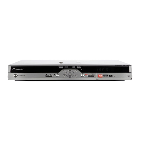
Page 129: Panel Facilities
Pull the cover down where indicated to access the front panel input jacks (audio, video and DV ). Especially Press to start or restart playback. convenient for connecting camcorders and other portable equipment. Press to pause or resume playback. Press to stop playback. DVR-533H-S... -
Page 130: Rear Panel Connections
CONTROL IN Use to control this recorder from the remote sensor of another Pioneer component with a CONTROL OUT terminal and bearing the Pioneer mark. Connect the CONTROL OUT of the other component to the CONTROL IN of this recorder using a mini-plug cord. - Page 131 Play List mode. Lights when the analog audio input level is too high. Shows the remote control mode (if nothing is displayed, the remote control mode is 1). Lights when an unfinalized Video mode disc is loaded. DVR-533H-S...
- Page 132 Press to open/close the disc tray. 16 RETURN Press to go back one level in the on-screen menu or Press to select the hard disk (HDD) for recording or display. Also use to exit the TV Guide On Screen™ playback. system. DVR-533H-S...
- Page 133 Also use to display the previous/next page of a TV Guide On Screen™ listing. STEP/SLOW During playback, press to start slow-motion playback; while paused, press to show the previous or next video frame. Also use to display the previous/next day of a TV Guide On Screen™ listing. DVR-533H-S...
- Page 134 Before shipping out the product, be sure to clean the following positions by using the prescribed cleaning tools: Position to be cleaned Cleaning tools Pickup lenses Cleaning liquid : GEM1004 Cleaning paper : GED-008 Position to be cleaned Cleaning tools Fans Cleaning paper : GED-008 DVR-533H-S...