Table of Contents
Advertisement
Advertisement
Table of Contents

Related Manuals for Carrier 42QH30-H


Summary of Contents for Carrier 42QH30-H
- Page 1 SERVICE & MAINTENANCE MANUAL 2005...
-
Page 2: Table Of Contents
TABLE OF CONTENTS PAGE NO. 1. Precautions for Service & Maintenance 2. Split System Description 3. Unit Model Designation & Identification 4. Unit Models & Part Numbers 5. System Operating Limits 6. System Safety Protections 7. Exploded View of Indoor Unit 8. -
Page 3: Precautions Before Installation
8- Refrigerant normal noise, wear and tear of deterioration. 9- Inconvenience or commercial loss is not covered. The decision of Carrier in ascertaining the same will be final. Any such repairs will be carried out at the expense of the purchaser. -
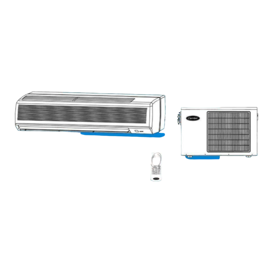
Page 4: Split System Description
2. SPLIT SYSTEM DESCRIPTION (c) RETURN AIR TO INDOOR UNIT (a) INDOOR UNIT The return air from the space to be air-conditioned passes Mounted inside the space to be air-conditioned. through the front return grille and top the through the anti- In summer it filters, dehumidifies and cools air. -
Page 5: Unit Model Designation & Identification
C = Cool Only At ARI Conditions 30 = 30,000 Btu/hr 36 = 36,000 Btu/hr 4. UNIT MODELS & PART NUMBERS INDOOR UNIT Heat Pump Cool Only Model Model 42QH30-H 46303188 42QH30-C 46303186 42QH36-H 46303189 42QH36-C 46303187 OUTDOOR UNIT Heat Pump... -
Page 6: System Operating Limits
5. SYSTEM OPERATING LIMITS COOLING HEATING Dry Bulb Wet Bulb Dry Bulb Wet Bulb Difference Difference Temp. C° Temp. C° Temp. C° Temp. C° Indoor temperature Indoor temperature Maximum Maximum Minimum Outdoor temperature Outdoor temperature Maximum Maximum Minimum 21** MAIN POWER SUPPLY Nominal System Minimum... -
Page 7: Exploded View Of Indoor Unit
7. EXPLODED VIEW OF INDOOR UNIT 24.2 24.3 24.7 24.1 24.4 24.5 24.6... -
Page 8: Part List Of Indoor Unit
8. PART LIST OF INDOOR UNIT QUANTITY / UNIT PART PART NAME 42QH- H 42QH- C NUMBER Mounting Bracket 02802426 Base Pan 02802427 End Plate Support – L 02802425 Blower L 02802434 Blower R 02802435 Bracket Motor 02802422 Center Bearing W/Bracket 02802423 Motor 02400017... -
Page 9: Exploded View Of Outdoor Unit
9. EXPLODED VIEW OF OUTDOOR UNIT 19/1 19/5 19/2 19/6 19/3 19/3... -
Page 10: Part List Of Outdoor Unit
02400154 7.2 Motor 1/5 HP-860 RPM 02400179 PROPELLER C/W SOCKET SET SCREW 8 X 8 MM 02600441 ORIFICE PROPELLER 02803112 COND. SHROUD 08107406 06307435 CARRIER LOGO 02900615 HANDLE 02803110 GUARD PROPELLER 02803113 COND. BACK PANEL 06307409 06307434 COUPLING PANEL 06307410... -
Page 11: Wiring Diagrams
11. WIRING DIAGRAMS INDOOR UNIT 42QH-H SERIES HEAT PUMP WIRING DIAGRAM INDOOR UNIT 42QH-C SERIES COOL ONLY WIRING DIAGRAM 0350151... - Page 12 WIRING DIAGRAMS (CONT.) OUTDOOR UNIT 38QH-H SERIES HEAT PUMP WIRING DIAGRAM OUTDOOR UNIT 38QH-C SERIES COOL ONLY WIRING DIAGRAM...
-
Page 13: Field Electrical Connections Matching
12. FIELD ELECTRICAL CONNECTIONS MATCHING HEAT PUMP SYSTEM OUTDOOR COOL ONLY SYSTEM COIL SENSOR LEGEND Outdoor Unit Indoor Unit Main Switch Time-delay fuse or circuit breaker Earth Live power supply. Neutral power supply. Live connection indoor/outdoor unit. Neutral connection indoor/outdoor unit Compressor control. -
Page 14: Refrigeration Cycle
13. REFRIGERATION CYCLE HEAT PUMP SYSTEM... - Page 15 REFRIGERATION CYCLE (Cont.) COOL ONLY SYSTEM...
-
Page 16: Self Diagnostic Function
14. SELF DIAGNOSTIC FUNCTION 14-1 INTRODUCTION - Self-diagnostic function is the key for success of heat pump system. - The printed circuit boards existing inside the indoor unit are equipped with self-diagnostic function to detect malfunction and automatically stops the operation at the air conditioner after blinking of power or timer led as per malfunction. -
Page 17: Air Filter Cleaning
15. AIR FILTER CLEANING - The air filters supplied with the unit are high-efficiency washable and recyclable filters. - To establish, how frequently these should be cleaned, the operating conditions must be taken in to account. - REMOVAL OF AIR FILTERS FOR CLEANING: Open the return grille without removing the two screws and the central clamp from their position. -
Page 18: Periodical Checks
16. PERIODICAL CHECKS For a good operation of the air conditioner it is recommended to carry out checks and maintenance as indicated. Recommended maintenance intervals may very depending on the installation environment, e.g. dusty zones, etc. Indoor Unit Every Month Every 4 Months Every Year Clean air filter... -
Page 19: Trouble Shooting
17. TROUBLE SHOOTING TROUBLE REASON ACTION Compressor and outdoor fan will not Power failure Call power company start Fuse blown or / and circuit breaker tripped Replace fuse or reset circuit breaker Detective contactor Replace Low line voltage Determine cause and eliminate Incorrect or loose wiring Check wiring diagram and rewire correctly Temp. - Page 20 TROUBLE SHOOTING (Cont.) TROUBLE REASON ACTION Head pressure too low Low refrigerant charge Check for leaks, repair and recharge Restriction in liquid tube Remove restriction Indoor section air filter dirty Clear filter Excessive section pressure Reversing valve hung up or internal leak Replace Internal pressure relief open Check for source and eliminate...
- Page 21 TROUBLE CHART (Cont.) TROUBLE REASON ACTION When pressing stop button, unit does Remote control batteries are exhausted. Replace batteries. not acknowledge signal with a beep. Remote control has not been pointed Turn remote control OFF and repeat the correctly to the receiver of indoor unit. operation in the correct direction.
- Page 22 TROUBLE CHART (Cont.) TROUBLE REASON ACTION Air conditioner is not supplying enough Air flow cannot circulate freely Remove obstructions. heating. Dirty filters reduce air quantity circulating. Clean air filters Doors and/or windows are open. Close doors and windows Fan speed has been set to “Low” Set fan speed at high speed.