Table of Contents
Advertisement
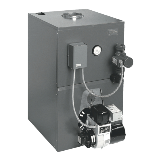
Models
BC3095
BC Series II
BC4100
OIL-FIRED CAST IRON BOILER
BC4115
INSTALLATION, OPERATION &
MAINTENANCE MANUAL
Maximum Allowable
Working Pressure 30
Manufactured by:
psi.
ECR International, Inc.
2201 Dwyer Avenue, Utica NY 13501
web site: www.ecrinternational.com
An ISO 9001-2008 Certified Company
P/N 240009511, Rev. B [12/2014]
Advertisement
Table of Contents

Related Manuals for UTICA BOILERS BC3095


Summary of Contents for UTICA BOILERS BC3095
- Page 1 Models BC3095 BC Series II BC4100 OIL-FIRED CAST IRON BOILER BC4115 INSTALLATION, OPERATION & MAINTENANCE MANUAL Maximum Allowable Working Pressure 30 Manufactured by: psi. ECR International, Inc. 2201 Dwyer Avenue, Utica NY 13501 web site: www.ecrinternational.com An ISO 9001-2008 Certified Company...
-
Page 2: Table Of Contents
SAFETY INFORMATION Ratings, Data, And Dimensions ................3 Installation Procedure ..................4 Ventilation And Combustion Air ................5 Connecting Supply And Return Piping ..............7 Venting System Inspection & Installation...............12 Electrical Wiring ....................14 Wiring Diagrams ....................15 Operating Instructions ..................16 Maintenance Procedures .................. - Page 3 DIMENSIONS Figure 1 - Dimensions Table 1 DIMENSIONS Length Front of Jacket Flue Tankless of Flush to Center Line Outlet Coil to Back Boiler No. Jacket of Flue Outlet Diameter of Jacket 19" 9 ¾" 6" 8⅞ 23" 11¾" 6" 12¾...
-
Page 4: Ratings, Data, And Dimensions
Capacity Boiler Model Rating G.P.H. Water MBH Round Square Number 0.95 84.0 8x8x15 BC3095 1.00 85.0 8x8x15 BC4100 1.15 84.0 8x8x15 BC4115 NOTES: 1. AHRI burner capacity is based on an oil heating value of 140,000 Btu/gal and with 13% 2. -
Page 5: Installation Procedure
INSTALLATION PROCEDURE WARNING DANGER Improper installation, adjustment, alteration, service Fire hazard. Do not install boiler on combustible or maintenance could result in death or serious flooring or carpeting. Failure to follow these injury. instructions WILL result in death or serious injury. •... -
Page 6: Ventilation And Combustion Air
VENTILATION AND COMBUSTION AIR Table 5 COMBUSTION AIR REQUIREMENTS (Minimum Opening Requirement) Unconfined Area* Confined Area** Outside Inside Outside Combustion Air BTU/Hr Combustion Air 1 Sq. Input Combustion Air 1 Sq. Vertical Ducts 1 Sq. Horizontal Ducts 1 Sq. In./1000 BTU/Hr In./4000 BTU/Hr In./2000 BTU/Hr In./5000 BTU/Hr... - Page 7 VENTILATION AND COMBUSTION AIR When the boiler is installed in a confined space and Figure 3 Boiler Installed In Confined Space - Air all air is provided from the outdoors, the confined From Outdoors space shall be provided with two permanent openings, one commencing within 12 inches from the top and one commencing 12 inches from the bottom of the enclosure.
-
Page 8: Connecting Supply And Return Piping
CONNECTING SUPPLY AND RETURN PIPING Circulators in the following illustrations are mounted on system supply side, mounting on system return side is also acceptable practice. Figure 6 Boiler Used In Connection With Refrigerated System Figure 7 Bypass Piping Typically Used With Baseboard Heating Connect supply and return piping as suggested in B. - Page 9 CONNECTING SUPPLY AND RETURN PIPING During heating cooling cycle open valves C and D, close B. This method is used to protect boilers from valves A and B. condensate forming due to low temperature return water. Generally noticed in large converted gravity A.
- Page 10 CONNECTING SUPPLY AND RETURN PIPING Figure 9 Bypass Piping Option Used to Protect From Converted Systems With High Water Temperature Figure 10 Typical Installation With Circulators...
- Page 11 CONNECTING SUPPLY AND RETURN PIPING Figure 11 Typical Installation With Valves Figure 12 Typical Installation With DHW...
- Page 12 CONNECTING SUPPLY AND RETURN PIPING WARNING Burn or Scald Hazard. Discharge line shall be installed to relief valve outlet connection to avoid burns, scalding, or water damage due to discharge of steam and/or hot water during operation. Discharge line shall: •...
-
Page 13: Venting System Inspection & Installation
VENTING SYSTEM INSPECTION & INSTALLATION Figure 15 Chimney Installation WARNING Boiler and venting installations shall be performed by a qualified expert and in accordance with the appropriate manual. Installing or venting boiler or other appliances with improper methods or materials may result in serious injury or death due to fire or to asphyxiation from poisonous gases such as carbon monoxide with is odorless and invisible. -
Page 14: Oil Tank And Piping
OIL TANK AND PIPING Oil Tank and Piping Installation • Install fuel pump connections and by-pass according to instructions attached to the fuel pump. If tank is more • Install oil tank and piping in accordance with the National than 20' from boiler, install two stage fuel unit in place Board of Fire Underwriters and local regulations. -
Page 15: Electrical Wiring
ELECTRICAL WIRING Thermostat Installation WARNING Thermostat should be installed on an inside wall about Electrical shock hazard. Turn OFF electrical power four feet above the floor. supply at service panel before making electrical NEVER install a thermostat on an outside wall. connections. -
Page 16: Wiring Diagrams
WIRING DIAGRAMS Figure 18 Wiring Diagram... -
Page 17: Operating Instructions
OPERATING INSTRUCTIONS Sequence of Operation • Thermostat calls for heat. • Circulator turns on. • Limit checks boiler water temperature. Burner ignition delayed until limit determines call for heat cannot be met by residual heat in boiler and heat distribution system. A. - Page 18 Air Band Air Shutter Pump Pressure Model Nozzle Furnished Type Disc Settings Settings (psi) BC3095 2¾ U Delevan 0.85x 80°B BC4100 2¾ U Delevan 0.85x 80°B BC4115 2¾ U Delevan 1.00x 80°B NOTES: Information in above table uses Beckett model AFG burner for both model numbers BC-3 and . BC-4...
-
Page 19: Maintenance Procedures
MAINTENANCE PROCEDURES Regular Maintenance NOTICE • Inspect venting system at start of each heating season. Do not overtighten bolts. Check vent pipe from boiler to chimney for signs Periodic inspection and tightening of tankless heater/ of deterioration by rust or sagging joints. Repair if cover plate bolts reduce the risk of leaks. -
Page 20: Service Checklist
Proper Light-Off (Hot & Cold) [ X ] * Measure with instruments and record results below. SERVICE RECORD Flue Nozzle Draft Pump Pressure Date Smoke# Temp °F Size Angle Type O.F. or O UTICA BOILERS 2201 Dwyer Avenue Utica NY 13501 web site: www.ecrinternational.com...