Sony ICF-C470 Service Manual
Hide thumbs
Also See for ICF-C470:
- Operating instructions (2 pages) ,
- Limited warranty (1 page) ,
- Operating instructions (2 pages)
Table of Contents
Advertisement
Advertisement
Table of Contents

Related Manuals for Sony ICF-C470


Summary of Contents for Sony ICF-C470
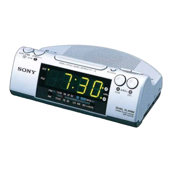
- Page 1 ICF-C470/C470L SERVICE MANUAL US Model Canadian Model Ver 1.1 1999. 06 E Model With SUPPLEMENT 1 Australian Model (9-926-981-81) ICF-C470 AEP Model ICF-C470/C470L UK Model ICF-C470L Photo: ICF-C470 SPECIFICATIONS ICF-C470 FM/AM CLOCK RADIO ICF-C470L FM/MW/LW 3 BAND CLOCK RADIO MICROFILM...
-
Page 2: Table Of Contents
WT-540A. Follow the manufacturers’ instructions to use these 6-1. Block Diagram ..............9 instruments. 6-2. Printed Wiring Boards (ICF-C470) ........ 11 2. A battery-operated AC milliammeter. The Data Precision 245 6-3. Schematic Diagram (ICF-C470) ........13 digital multimeter is suitable for this job. -
Page 3: General
SECTION 1 This section is extracted from instruction manual. GENERAL – 3 –... -
Page 4: Disassembly
SECTION 2 DISASSEMBLY Note: Follow the disassembly procedure in the numerical order given. CABINET (LOWER) 1 five screws (P3 × 14) 3 cabinet (lower) 2 two claws MAIN BLOCK 1 power transformer 5 buzzer board 6 Break the soldering of speaker lead. 3 main block 4 two claws 2 three claws... -
Page 5: Dial Pointer Setting
SECTION 3 DIAL POINTER SETTING Note: Follow the assembly procedure in the numerical order given. 5 Install the MAIN board. 4 Turn VR1 to the arrow D direction fully. – BOTTOM VIEW – 3 Turn shaft of CV1 to the arrow C direction fully. -
Page 6: Power Cord Setting
SECTION 4 POWER CORD SETTING Set the power cord as illustrated below, then install the lower cabinet. FM antenna power cord lower cabinet – 6 –... -
Page 7: Electrical Adjustments
0 dB = 1 µV Adjust for a maximum reading on level meter [AM (MW/LW)*] 455 kHz * AM : ICF-C470 MW/LW : ICF-C470L AM (MW *2) FREQUENCY COVERAGE ADJUSTMENT Setting: Adjust for a maximum reading on level meter Band switch: AM (MW/LW) - Page 8 Adjustment Location: – MAIN BOARD (Component Side) – L1 (L1-1 * ) AM (MW * ) Tracking Adjustment AM IF Adjustment CT1-2 FM Tracking Adjustment FM Frequency Coverage Adjustment CT1-1 CT1-4 L1-2 AM (MW * ) Tracking Adjustment Tracking Adjustment * AM (MW * ) Frequency CT1-3 Coverage Adjustment...
-
Page 9: Diagrams
ICF-C470/C470L SECTION 6 DIAGRAMS 6-1. BLOCK DIAGRAM CT1-2 FM TRACKING • SIGNAL PATH FM RF : FM FM/AM FRONT-END, ANT1 CV1-2 CT1-2 FM/AM IF AMP, DET, AGC, AF AMP : AM (MW/LW) TUNING FM LEAD ANTENNA • Abbreviation E13: 220 – 230 V AC 50/60Hz... -
Page 11: Schematic Diagram (Icf-C470)
ICF-C470/C470L 6-3. SCHEMATIC DIAGRAM (ICF-C470) • See page 19 for IC Block Diagrams. Note on Schematic Diagram: • All capacitors are in µF unless otherwise noted. pF: µµF 50 WV or less are not indicated except for electrolytics and tantalums. -
Page 13: Schematic Diagram (Icf-C470L)
ICF-C470/C470L 6-5. SCHEMATIC DIAGRAM (ICF-C470L) • See page 19 for IC Block Diagrams. Note on Schematic Diagram: • All capacitors are in µF unless otherwise noted. pF: µµF 50 WV or less are not indicated except for electrolytics and tantalums. -
Page 14: Exploded Views
ICF-C470/C470L SECTION 7 EXPLODED VIEWS NOTE: • IC Block Diagrams • -XX and -X mean standardized parts, so they • Items marked “*” are not stocked since they The components identified by – MAIN BOARD – mark ! or dotted line with mark may have some difference from the original are seldom required for routine service. - Page 15 (2) CHASSIS SECTION ANT1 LED1 C470: AEP, IT, E13, SP/ C470L The components identified by mark ! or dotted line with mark ! are critical for safety. Replace only with part number specified. Les composants identifiés par une marque ! sont critiquens pour la sécurité.
-
Page 16: Electrical Parts List
BUZZER KEY (A) SECTION 8 ELECTRICAL PARTS LIST KEY (B) MAIN NOTE: The components identified by mark • Due to standardization, replacements in the • Items marked “*” are not stocked since they ! or dotted line with mark ! are parts list may be different from the parts speci- are seldom required for routine service. - Page 17 MAIN Ref. No. Part No. Description Remark Ref. No. Part No. Description Remark 1-126-963-11 ELECT 4.7uF < TRIMMER > (C470L) 1-128-551-11 ELECT 22uF 1-141-529-11 CAP, VARIABLE 1-126-925-11 ELECT 470uF (C470: AEP, IT, E13, SP, AUS/C470L) 1-109-982-11 CERAMIC CHIP 1-151-628-11 CAP, VARIABLE (C470: US, CND, E92) (C470L) 1-141-604-11 CAP, ADJ (C470L) 1-164-505-11 CERAMIC CHIP...
- Page 18 MAIN TRANSFORMER Ref. No. Part No. Description Remark Ref. No. Part No. Description Remark JC43 1-216-296-00 SHORT 0 (C470: E13) 1-216-097-00 RES, CHIP 100K 1/10W (C470L) < LED > 1-216-198-00 RES, CHIP 1/8W LED1 8-749-015-49 LED SL-1906-54T (DATE DISPLAY) ! R22 1-249-399-11 CARBON 1/4W F (C470: US, CND, E92)
- Page 19 Ref. No. Part No. Description Remark Ref. No. Part No. Description Remark MISCELLANEOUS ************** 1-555-795-00 CORD, POWER (C470: AEP, IT, E13, SP/C470L: AEP) 1-696-572-21 CORD, POWER (C470L: UK) 1-769-339-22 CORD, POWER (C470: E92) 1-783-817-11 CORD, POWER (C470: US, CND) 1-790-431-11 CORD, POWER (C470: AUS) ANT1 1-501-907-21 ANTENNA, FM WIRE 1-504-748-21 SPEAKER (6.6cm)
- Page 20 ICF-C470/C470L Sony Corporation 99C0582-1 Printed in Japan © 1999. 3 9-926-981-11 Personal A&V Products Company Published by Quality Engineering Dept. – 26 – (Shinagawa)
- Page 21 ICF-C470/C470L US Model Canadian Model SERVICE MANUAL E Model Australian Model ICF-C470 1999. 06 AEP Model ICF-C470/C470L UK Model ICF-C470L SUPPLEMENT-1 File this supplement with the service manual. Subject: Addition of East Europe, Russia Model (ICF-C470L) (ENG-99007) • DIFFERENCE PARTS LIST ACCESSORIES &...
- Page 22 This file has been downloaded from: www.electronica.ro Service Manuals, Schematic Diagram, Repair...