Motorola IDEN I580 Field Service Manual
Basic and field level test procedures digital multi-service, data-capable portable
Hide thumbs
Also See for IDEN I580:
- User manual (233 pages) ,
- User manual (220 pages) ,
- User manual (222 pages)
Table of Contents
Advertisement
Quick Links
Download this manual
See also:
User Manual
Advertisement
Table of Contents

Related Manuals for Motorola IDEN I580


Summary of Contents for Motorola IDEN I580
- Page 1 Field Service Manual Basic and Field Level Test Procedures iDEN Digital Multi-Service, Data-Capable Portable...
- Page 2 i580 Digital Multi-Service, Data-Capable Portable Field Service Manual Basic and Field Level Test Procedures 2006 68P80401P05...
- Page 3 The Motorola products described in this manual may include Motorola computer programs stored in semiconductor memories or other media that are copyrighted with all rights reserved worldwide to Motorola. Laws in the United States and other countries preserve for Motorola, Inc. certain exclusive rights to the copyrighted computer programs, including the exclusive right to copy, reproduce, modify, decompile, disassemble, and reverse-engineer the Motorola computer programs in any manner or form without Motorola’s prior written consent.
-
Page 4: Safety And General Information
To maintain compliance with FCC RF exposure guidelines, if you wear a radio product on your body when transmitting, always place the radio product in a Motorola approved clip, holder, holster, case or body harness for this product. Use of non-Motorola-approved accessories may exceed FCC RF exposure guidelines. -
Page 5: Medical Devices
SAFETY AND GENERAL INFORMATION ALL MODELS WITH FCC ID AZ489FT5848 MEET THE GOVERNMENT'S REQUIREMENTS FOR EXPOSURE TO RADIO WAVES. Your wireless phone is a radio transmitter and receiver. It is designed and manufactured not to exceed the emission limits for exposure to radiofrequency (RF) energy set by the Federal Communications Commission of the U.S. -
Page 6: Operational Cautions
Operational Warnings For Vehicles Equipped with an Air Bag Do not place a portable radio product in the area over the air bag or in the air bag deployment area. Air bags inflate with great force. If a portable radio is placed in the air bag deployment area and the air bag inflates, the radio product may be propelled with great force and cause serious injury to occupants of the vehicle. - Page 7 SAFETY AND GENERAL INFORMATION • Use of a non-recommended attachment to a battery charger may result in a risk of fire, electric shock, or injury to persons. • Make sure the battery charger power cord is located so that it will not be stepped on, tripped over, or subjected to damage or stress.
- Page 8 MODEL INFORMATION This manual applies to the following iDEN i580 Digital Portable models: H83XAH6RR4AN 806-940 MHz, Multi-Service, Data-Capable Portable MODEL NUMBERING SYSTEM Typical Model Number: Position: Position 1 - Type of Unit H = Hand-Held Portable M = Mobile Product...
-
Page 9: Model Specifications
MODEL SPECIFICATIONS MODEL SPECIFICATIONS GENERAL FCC Designation: AZ489FT5848 Receiver Type: Operational Modes: Phone Private Group Circuit Data 800 MHz Band only: Packet Data MotoTalk Temperature Range: Operating –10°C to +60°C Storage (w/o battery) –40°C to +85°C Power Supply: Battery Type Lithium Ion Recommended Battery:... -
Page 10: Table Of Contents
Contents SAFETY AND GENERAL INFORMATION ... MODEL INFORMATION... MODEL SPECIFICATIONS ... PREFACE... Who Should Use This Manual ... How This Manual Is Organized... Conventions Used in This Manual ... Related Publications ... CHAPTER 1 OVERVIEW... i DEN Digital Modulation Technology... i DEN Voice Compression Technology ... - Page 11 Preventive Maintenance ... Mechanical and Electrical Checks ... SIM Card Swap Test... Accessory Swap Test ... Lockup Test ... Battery Connections Test ... Testing the GPS Receiver ... Voltage Recognition Test... Self-Test Procedures ... Passcode Test ... Programming Menu Settings Check ... Call Performance Test ...
- Page 12 Remove Flip Assembly ... Procedure to remove flip assembly: ... Install Flip Assembly ... Procedure to install flip assembly: ... Exploded View and Parts List ... i580 Component Parts List ... i580 Exploded View ... CHAPTER 8 FIELD LEVEL TEST MODES AND PROCEDURES... Test Modes ...
- Page 13 J401 (30 Pin Board-to-Flex Connector) ... J400 (80 Pin Board-to Flex Connector) ... M002 (SIMM Connector) ... M105 (Battery Contact... M2 (2 Pin-Contact)... J753 (Microphone Socket)... SW-all (Key/Switch) ... D401 through D412 (LED) ... APPENDIX A ORDERING REPLACEMENT PARTS AND KITS ... Customer Service ...
-
Page 14: Preface
The iDEN i580 Digital Multi-Service, Data-Capable Portable Field Service Manual contains the information necessary to identify and fix problems in the Motorola i580 Digital Portable. This unit is based on digital technology and is designed to operate on iDEN systems. -
Page 15: Conventions Used In This Manual
Defines menu items, fields, and buttons Used for sample input and output code Related Publications The following publications are available separately: iDEN i580 Digital Multi-Service Data-Capable Phone User’s Guide R-2660 Digital Communications System Analyzer Operator’s Manual NNTN6775A 68P80386B72 68P80401P05... -
Page 16: Chapter 1 Overview
CHAPTER 1 OVERVIEW To achieve a high spectrum efficiency, the i580 digital multi-service, data-capable portable uses a unique modulation technology and sophisticated voice-compression algorithm. The voice of the person speaking into the microphone is converted into a digital bit stream consisting of zeros (0) and ones (1). - Page 17 OVERVIEW: i DEN Digital Modulation Technology RL 0dBm Power (dB) Figure 1-1. Spectrum of i DEN Quad 16QAM Quadrature Phase Shift Keying (QPSK) is one of the most common modulation techniques for satellite communications. In QPSK, a digital data stream is taken two bits at a time to generate four possible phase states of the transmitted carrier.
-
Page 18: Den Voice Compression Technology
algorithms and one digital-signal processor (DSP) to perform voice compression/decompression and RF modulation/demodulation. Base Station Control Channel Transmitting 6 of 6 slots continually. 15ms 15ms 15ms 15ms 15ms 15ms Receiver 4ms delayed Portable Unit When turned on, scans for control station, then transmits one slot every six slots. 15ms 15ms 15ms... -
Page 19: Calling Area Coverage
OVERVIEW: i DEN Voice Compression Technology (GPS) system. Each burst is numbered; the number is referred to as the slot number. All bursts occurring at a given time carry the same slot number. Inbound transmission bursts (sent from the unit) are offset 19 milliseconds from the outbound burst; the inbound burst begins 4 milliseconds after the end of the outbound burst (see Figure 1-2 on page 1-3). -
Page 20: Global Positioning System (Gps) Section
It is a PTT (Push-To-Talk)- based feature that operates like most any two-way radio might. A good basic model for operation is that of the Motorola Talkabout product. What makes it quite different, however, is that it is digital in operation, which allows for superior range and voice quality. -
Page 21: Sim Cards
OVERVIEW: SIM Cards SIM Cards This unit is designed to work with a mini Subscriber Identity Module (SIM). The SIM card contains all of the personal data required to access iDEN services. Data held by the SIM card includes: • Temporary Mobile Subscriber Identity •... - Page 22 OVERVIEW: SIM Cards Figure 1-3. Removing a SIM Card To insert a SIM card (Figure 1-4): 1. Open the SIM card holder. 2. Carefully slide the SIM card into the holder (see Figure 1-4). Position SIM card as shown. 3. Close SIM door, slide latch to shut. 4.
-
Page 23: Features, Icons, And Indicators
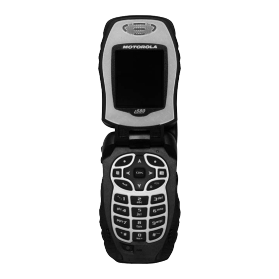
FEATURES, ICONS, AND INDICATORS: i 580 Features CHAPTER 2 FEATURES, ICONS, AND INDICATORS To conduct basic troubleshooting and maintenance of the i580 unit, you must become familiar with the components, display icons, and status indicators associated with the unit. i 580 Features Speaker Key;... -
Page 24: Display Icons
Display Icons Icons for this unit provide information that is useful for troubleshooting and testing purposes. All features can be accessed through the main menu. When using a feature, the icon for that feature appears in the upper left corner of the display. Depending upon features and options chosen, the following icons can appear on the unit’s display. -
Page 25: Status Icons
FEATURES, ICONS, AND INDICATORS: Display Icons 2.2.2 Status Icons Status icons appear in the two rows at the top of the display. Some appear at all times. Others appear only when your phone is engaged in certain activities or when you have activated certain features. Battery Strength—Indicates the battery’s stored level of charge. -
Page 26: Displays, Messages, And Alerts
CHAPTER 3 DISPLAYS, MESSAGES, AND ALERTS To conduct basic troubleshooting and maintenance of the i580 unit, you must become familiar with the display screens, messages, and alert tones associated with the unit. Power-Up Sequence Extend the antenna whip and press the Power key until the power-up sequence begins. The power- up sequence initiates a series of displays on the unit. -
Page 27: Power-Down Sequence
DISPLAYS, MESSAGES, AND ALERTS: Power-Down Sequence Power-Down Sequence To power down the unit, press and hold the Power key until the unit begins powering down. Messages 3.3.1 Self-Test Errors The following table contains the list of self-test non-reset errors. These errors are displayed as SELF CHECK ERROR YXXXX (YXXXX represents the identifier for that error). -
Page 28: Service Messages
3.3.3 Service Messages Service messages indicate the probable cause of a problem. The following table lists the messages, their probable causes, and recommended corrective actions. Table 3-3. Service Messages Message Cause Charger Attached While Power Down Device Attached 17-Pin connector plugged in while powered up. -
Page 29: Alert Tones
Data Ringer Spkr DTMF (0-9, #, *) Earpiece Volume Action Reboot unit. If problem persists, contact Motorola Make sure user is out in clear sky and stationary. If problem persists, reboot unit. Report problem to provider Try call again later... - Page 30 Table 3-4. Alert Tones (Continued) Tone High Group Call Alert Spkr Spkr In Service Spkr Spkr Interconnect Busy Invalid Key Low Battery in Idle Spkr Spkr Keypad Volume Message Mail Spkr Spkr Received in Idle Msg Mail Received in Interconnect Message Volume Spkr Spkr...
- Page 31 DISPLAYS, MESSAGES, AND ALERTS: Alert Tones Table 3-4. Alert Tones (Continued) Tone High Phone Ring (U.S.) Spkr Spkr Phone Ring Back Private Call Spkr Spkr Received Reject Spkr Ringer Volume Set Spkr Spkr Sat No Fix Spkr Spkr Self-Test Fail Spkr Spkr Freq...
-
Page 32: Using The Optional Vibrate Function
Table 3-4. Alert Tones (Continued) Tone High Speaker Volume Spkr Spkr System Busy Spkr Talk Permit Spkr Talk Prohibit Spkr TOT Warning Spkr Valid Key Press Voice Mail Spkr Spkr Received in Idle Voice Mail Received in Interconnect Using the Optional Vibrate Function The vibrate function (VibraCall) notifies the user of incoming phone or dispatch calls, DC/GC calls, messages, notifications, and call alerts. - Page 33 DISPLAYS, MESSAGES, AND ALERTS: Using the Optional Vibrate Function To set unit to vibrate for Direct Connect and Group Connect calls only: 1. From the main menu, select Settings > 2-Way Radio > Alert Type. 2. If Alert Type does not appear, from the main menu select Ring Tones. Make sure Vibrate All or Silent All is set to Off.
-
Page 34: Preparing For Basic Level Testing
PREPARING FOR BASIC LEVEL TESTING Test Equipment The following equipment is useful when testing an i580 unit: a reference unit, a reference SIM card, and reference accessories. For a list of recommended test and programming equipment used to troubleshoot this unit, see Appendix A: Ordering Replacement Parts and Kits. 4.1.1 Reference Unit Use a reference unit (i580 unit known to be in good working order) to verify the accuracy of some tests. -
Page 35: Basic Level Checks And Self Tests
BASIC LEVEL CHECKS AND SELF TESTS: Customer Care CHAPTER 5 BASIC LEVEL CHECKS AND SELF TESTS Before you perform basic troubleshooting and self tests on an i580 unit, determine if any special conditions could affect testing and check the units for defective parts. There are five categories of basic tests: •... -
Page 36: Basic-Level Test Checklist
Basic-Level Test Checklist Use the following checklist to ensure that all the necessary tests are performed and to provide a tracking mechanism in case the unit is sent to the next level of service. Check the appropriate box for each test performed and indicate whether or not the test was completed successfully. Table 5-1. -
Page 37: Mechanical And Electrical Checks
BASIC LEVEL CHECKS AND SELF TESTS: Mechanical and Electrical Checks 3. Remove any dirt from the unit using a stiff, non-metallic, short-bristled brush. 4. Wipe and dry the unit with a soft, absorbent, lint-free cloth. Make sure that there are no damp spots on the connectors or in cracks and crevices. -
Page 38: Accessory Swap Test
4. Replace the SIM card with the test (reference) SIM card. Ensure the test SIM card is clean. 5. Power on the unit, and verify that the test SIM card works with the unit. If the unit works, the customer’s SIM card is defective and should be replaced, or the problem is due to operator error, system, or carrier. -
Page 39: Battery Connections Test
BASIC LEVEL CHECKS AND SELF TESTS: Mechanical and Electrical Checks 3. Press each of the alphanumeric keys to see if the unit responds. If the unit does not respond to a pressed key, remove the battery to cycle power on. If the problem persists after several tries, replace the unit. -
Page 40: Voltage Recognition Test
5. Scroll down on the GPS menu until the “POSITION” option is selected. 6. Press SELECT. The unit will display a “Position” information sheet. 7. Press RFRSH. The unit will respond with “Scanning for Satellites” or “Satellite Data Is Outdated, Continue?” depending upon whether the GPS Almanac is up-to-date or not. 8. -
Page 41: Passcode Test
BASIC LEVEL CHECKS AND SELF TESTS: Self-Test Procedures The following self-tests can be performed on an i580 unit: • Passcode • Programming Menu Settings • Call Performance 5.6.1 Passcode Test Use this test to determine the passcode for the unit. The Passcode test time is approximately 5 minutes: 1. - Page 42 • Large Dialing — Displays transient large number text while dialing. Settings > Display/Info > Large Dialing > OK. • Contrast — sets the contrast on the display. To set the contrast of the display: From the main menu, select Settings >Display/Info > Contrast. Press the OK button to change.
- Page 43 BASIC LEVEL CHECKS AND SELF TESTS: Self-Test Procedures Choose the option you want: Receive All — Tones sound during calls for all types of messages. Msg Mail Only — Tones sound during calls for mail messages; tones for all other types of messages are held until you end calls.
- Page 44 Personalize • Menu Options — User can reorder menu items and add/remove stored applications. Settings > Personalize> Menu Options > OK > Reorder Menu. Settings > Personalize> Menu Options > OK > Add/Remove Apps. • Up Key — At idle, user can press UP key as shortcut to selected application. Settings >...
- Page 45 BASIC LEVEL CHECKS AND SELF TESTS: Self-Test Procedures • Phone Lock — turns on a feature that locks your phone, either immediately or automatically after a set period of inactivity. An unlock code is required to enable this feature, to unlock the phone, and to set a new Unlock code.
-
Page 46: Call Performance Test
Enter the new 4- to 8-digit GPS PIN. Press the Ok button. Enter the new 4- to 8-digit GPS PIN to confirm. Press the Ok button. • Change Password — changes your phone unlock code, security code SIM PIN, and GPS PIN. Advanced Features The Advanced menu contains advanced and rarely used Settings features. - Page 47 BASIC LEVEL CHECKS AND SELF TESTS: Self-Test Procedures Required equipment: reference unit The Call Performance test time is approximately 7 minutes: 1. Power up the unit. Wait until registration is complete before continuing. 2. Place an interconnect call from the problem unit to the reference unit. 3.
-
Page 48: Basic Level Test Modes And Procedures
CHAPTER 6 BASIC LEVEL TEST MODES AND PROCEDURES To complete basic testing of an i580 unit, you must enter a test mode to retrieve data from the unit, and perform the technician tests in the correct sequence with the appropriate equipment. Test procedures are listed in the order in which they should be implemented. -
Page 49: Trace Mode Display Screens
BASIC LEVEL TEST MODES AND PROCEDURES: Test Modes To exit Debug Mode, press the option key under Back. 6.1.2 Trace Mode Display Screens Display screens on this unit provide information that is useful for troubleshooting purposes. These displays appear only when the unit is placed in Debug Mode (see “Entering Debug Mode” on page 6-1). - Page 50 Table 6-1. Display Screens (Continued) Name Description N6:1 Intrcnct Parameter details for the 6:1 Interconnect Feature enabling transmission of RF-originated messages through the telephone system. Line 1 shows MS, the Mobile Subscriber's ability to support 6:1 Interconnect and FNE, the Fixed Network Equipment’s ability to support 6:1 Interconnect respectively.
-
Page 51: Entering Test Mode
BASIC LEVEL TEST MODES AND PROCEDURES: Test Mode Test Procedures Table 6-1. Display Screens (Continued) Name Description Resets: Displays the Reset Error log. This log contains any errors logged when the user resets the unit during operation. The most recent reset appears at the top of the list. Pressing Menu when it appears displays the Clearall screen in which the user can clear all the logged errors. -
Page 52: Esn And Imei Matching Test
The Audio Loopback test time is approximately 3 minutes: 1. Enter Test Mode. 2. With the Test Mode screen displayed, press Menu. The right option key changes to Edit. 3. Press the option key under Edit. The right option key changes to Change. 4. - Page 53 BASIC LEVEL TEST MODES AND PROCEDURES: Test Mode Test Procedures NOTE: The following procedure describes the sequence of displays accessed via the down scroll key. If you press the up scroll key, the sequence appears in reverse order. To monitor the data in the unit: 1.
- Page 54 11. Press Back to return to the Trace Mode display. 12. Scroll down to highlight GPS, and then press View to view the GPS display. a. Location selection displays the number of satellites used to obtain the position fix, the current cell site latitude and longitude, the subscriber unit latitude and altitude information, as well as the last calculated horizontal and vertical accuracy.
-
Page 55: Technician Test Procedures
BASIC LEVEL TEST MODES AND PROCEDURES: Technician Test Procedures 24. Scroll down to highlight Band Info, and then press View to view the Band Info display. This screen displays the primary and secondary control channels: Pri Band: 02 for 800 MHz; Sec Band: 02 for 800 MHz and 04 for 900 MHz. -
Page 56: Programming The I580 Unit
Use Radio Service Software (RSS) to activate a new software utility or to program specific codeplug user information. Refer to Radio Service Software’s Help Menu, iDEN Service Bulletins, the Motorola iDEN website, or contact iDEN Customer Care for information on the setup and use of RSS. -
Page 57: Codeplug Help
BASIC LEVEL TEST MODES AND PROCEDURES: Connecting the Unit to the RSS Workstation Refer to any relevant Radio Service Software Read-Me’s or active iDEN Service Bulletins for more information on setting up your test computer as an RSS workstation. NOTE: For faster codeplug reading using an RS-232 connector, enable the QuickComm feature in the RSS configuration setup. -
Page 58: Preparing For Field Level Testing
• Ground the working surface of your service bench. If possible, use the Motorola Static Protection Assembly (P/N 0180386A82) to ground your service bench. This assembly contains a wrist strap, two ground cords, a table mat, and a floor mat. -
Page 59: Using Rss
Prior to touching any printed-circuit board, touch an electrical ground to remove any static charge that might have accumulated. Refer to Service and Repair Note SRN-F1052 for more information. This note is available through: Motorola Literature Distribution Center 2290 Hammond Drive Schaumburg, IL 60173... - Page 60 5.0 to 12.0 Vdc Power Supply To connect the unit to the R-2660: 1. Ensure the unit is powered off, and then turn on the R-2660. 2. Remove the battery cover and battery from the unit, and insert the reference SIM card. 3.
-
Page 61: Operating The R-2660
PREPARING FOR FIELD LEVEL TESTING: Operating the R-2660 10. Power up the subject unit. Refer to the R-2660 Digital Communications System Analyzer Operator’s Manual for more information on how to use this equipment. Operating the R-2660 Most of the technician tests performed with the R-2660 Communications System Analyzer require that the analyzer use the Initial Registration test mode. -
Page 62: Disassembling And Reassembling The Unit
Disassembling and Reassembling the Unit Motorola recommends the service technician follow a prescribed disassembly sequence to access specific items or components of the unit. This product is an efficiently designed package that incorporates the physical overlap and integration of some modular components. Refer to the Disassembly Sequence Flowchart for a suggested path to reach specific components. -
Page 63: Remove Battery Cover
PREPARING FOR FIELD LEVEL TESTING: Remove Battery Cover Remove Battery Cover 7.8.1 Remove: 1. Place thumb or fingernail against release latch (see Figure 7-2). 2. Push or pull down latch. 3. Hold latch in the down position and use fingernail to lift cover off housing bottom edge. 4. -
Page 64: Remove Battery
Remove Battery 7.9.1 Remove: 1. Place fingernail against the battery base exposed section. 2. Push the battery up towards unit’s top to release from bottom clip and lift up the battery to remove. 68P80401P05 PREPARING FOR FIELD LEVEL TESTING: Remove Battery Figure 7-3. -
Page 65: Remove Sim Card
PREPARING FOR FIELD LEVEL TESTING: Remove SIM Card 7.10 Remove SIM Card 7.10.1 Remove: 1. Slide tray lock away from SIM tray. 2. Open SIM Card Tray by lifting at tray access tab. 3. Grasp exposed corner of SIM Card and pull to slide SIM Card out. 7.11 Remove Antenna Tools: Required Tools: T4 Torx Bit, Tweezers. - Page 66 2. Extend antenna whip fully. 3. Hold unit stationary while tugging at collar until antenna assembly releases. 4. Insert tweezers into the antenna housing port, grab the edge of antenna tube and pull it out. 7.11.2 Install: 1. Carefully push antenna collar into position. 2.
-
Page 67: Remove Back Housing
PREPARING FOR FIELD LEVEL TESTING: Remove Back Housing 7.12 Remove Back Housing Tools: T-4, T-6 Torx Bits, Black Stick. Preparation: Remove Battery Cover, Battery, and Antenna. 7.12.1 Remove: 1. Remove four T-6 screws—one in the antenna tube channel. 2. Grasp the back housing at the top end and the front housing at the flip pivots. Gently pull apart the housing halves. -
Page 68: Remove Main Board, Keypad
7.13 Remove Main Board, Keypad Tools: Black Stick, Tweezers. 7.13.1 Remove: 1. Wedge black stick under flip flex connector. Gently pry upwards along length until release. 2. Lift main board straight up from housing bosses. 3. Remove the housing keypad backer. 4. -
Page 69: Remove Flip Assembly
PREPARING FOR FIELD LEVEL TESTING: Remove Flip Assembly 7.14 Remove Flip Assembly 7.14.1 Procedure to remove flip assembly: Tools: Black stick. NO metallic tools! NOTE: i580 flip components include a Flex Connector ribbon which can be easily torn or damaged if not handled properly. Handle the Flex Ribbon with care especially when working it through the front housing slot. - Page 70 4. While carefully pushing the black stick in towards the flip assembly about 2mm, twist the stick as if you were tightening a screw. 5. Try to compress the hinge spring by moving the stick in a shoveling motion. The front housing will deflect slightly, allowing the hinge to release the right side from the front housing.
-
Page 71: Install Flip Assembly
PREPARING FOR FIELD LEVEL TESTING: Install Flip Assembly 7.15 Install Flip Assembly 7.15.1 Procedure to install flip assembly: Tools: Black stick. NOTE: Ensure the flip and housing pivot points are clean. 1. Insert the Hinge Assembly Mechanism into flip right knuckle. Gently press inward until seated and ensure that the two surfaces are flush. - Page 72 6. Align the flip to the front housing to resemble closed flip. Using the black stick, push the Hinge Assembly Mechanism inward into the right knuckle of the front housing. 7. Once set, check the hinge position by opening and closing the flip looking for binding or other unusual action.
-
Page 73: Exploded View And Parts List
PREPARING FOR FIELD LEVEL TESTING: Exploded View and Parts List 7.16 Exploded View and Parts List This section contains the component parts list and exploded view for the i580 unit. i580 Component Parts List Black/Yellow Grey Tanapa 68P80401P05... -
Page 74: I580 Exploded View
PREPARING FOR FIELD LEVEL TESTING: Exploded View and Parts List i580 Exploded View 68P80401P05... -
Page 75: Field Level Test Modes And Procedures
FIELD LEVEL TEST MODES AND PROCEDURES: Test Modes CHAPTER 8 FIELD LEVEL TEST MODES AND PROCEDURES To perform field level testing on the i580 unit, you must enter a test mode to retrieve data from the unit, and perform the technician tests in the correct sequence with the appropriate equipment. NOTE: All tests should be performed in an RF interference-free environment. -
Page 76: Required Test Equipment
The following tests are performed in Test Mode: • TX Power Test • BER Tests 800BER1 800BER2 800BER3 800BER4 900BER1 900BER2 900BER3 NOTE: The Power, MPX, and MOD test parameters are for factory use only and should not be adjusted by field service personnel. The default values for these parameters are as follows: •... - Page 77 FIELD LEVEL TEST MODES AND PROCEDURES: Field-Level Test Checklist Table 8-4. Field-Level Test Checklist Done Technical Tests Registration/Call TX Power 800BER1 800BER2 800BER3 800BER4 900BER1 900BER2 900BER3 Power-Up Keypad Audio Reset Reset Log GPS Receiver MA Test Mode Pass Fail 68P80401P05...
-
Page 78: Registration/Call Test
Registering failures. (Use a reference unit to get a baseline.) Note: For 900 MHz verification, please perform the BER Test. May require ordering additional option for test. Contact Motorola Customer Service (see Appendix A). Set up the R-2660 for iDEN Mobile operation, and connect the unit to the RF IN/OUT connector. -
Page 79: Signal Quality Error (Sqe) Test
FIELD LEVEL TEST MODES AND PROCEDURES: Signal Quality Error (SQE) Test Signal Quality Error (SQE) Test Use this test on a unit having any of the following symptoms: No service failures or poor SQE/RSSI (poor performance in known good coverage area). Set up the R-2660 for iDEN Mobile operation, and connect the unit to the RF IN/OUT... -
Page 80: Tx Power Test
TX Power Test Use this test on a unit having bad transmission (TX) or intermittent service failures. (This is a transmitter test only.) Set up the R-2660 for Spectrum Analyzer display, and connect the unit to the RF IN/OUT connector. Connect the regulated battery eliminator to the unit to be tested. -
Page 81: Bit Error Rate (Ber) Test
FIELD LEVEL TEST MODES AND PROCEDURES: Bit Error Rate (BER) Test Bit Error Rate (BER) Test Use this test on a unit having any of the following symptoms: resets (RAAAA Type), No Service failures. Set up the R-2660 for iDEN BER Test, and connect the unit to the RF IN/OUT connector. -
Page 82: Power-Up Test
Power-Up Test Use this test to check power-up. Symptoms: dead battery, short battery life, or unit does not power Try to power up the unit. Pass Verify that the display pixels light up. Pass Check the battery-level meter for 3 bars on the unit’s display. -
Page 83: Keypad Test
FIELD LEVEL TEST MODES AND PROCEDURES: Keypad Test Keypad Test Use this test to check the operation of the unit’s keypads and display. Symptoms: unit locked, or stuck key Power up the unit. Enter the Model Assem- bly (MA) Test Mode. Verify that all the display tests complete... -
Page 84: Audio Test
8.10 Audio Test Use this test to check the audio portion of the unit. Set up the R-2660 for iDEN Mobile operation, and connect the unit to the RF IN/OUT connector. Place an interconnect call. (See Registration/Call test.) Pass Note: Set the R-2660 volume to maximum. -
Page 85: Reset Test
FIELD LEVEL TEST MODES AND PROCEDURES: Reset Test 8.11 Reset Test Use this test on a unit having any of the following symptoms: unit resets, or unit powers off and then Set up the R-2660 for iDEN Mobile operation, and connect the unit to the RF IN/OUT connector. -
Page 86: Reset Log Test
8.12 Reset Log Test Use this test to check the reset log in the unit. To perform the reset log test: 1. Power on the unit and wait until registration is complete. 2. If the unit does not have the latest software version, reflash (reprogram) the unit. If the unit attempts to reset, perform the Reset test (see page 8-11). -
Page 87: 8.13 Model Assembly (Ma) Test Mode Test
Model Assembly Test Mode is an embedded series of operational tests of the unit’s user interface and functional features. • Motorola iDEN recommends MA Test Mode be performed after any servicing of the unit. • An audio test cable is required to complete MA Test Mode effectively. See the Required Tools section or contact Motorola’s Aftermarket Accessories Division (AAD). -
Page 88: Gps (Global Positioning System) Receiver Test
FIELD LEVEL TEST MODES AND PROCEDURES: GPS (Global Positioning System) Receiver Test 8.14 GPS (Global Positioning System) Receiver Test Use this test on a unit to check its GPS functionality. Find an open sky area. Extend antenna and power up unit. Activate Phone returns... -
Page 89: Mototalk
FIELD LEVEL TEST MODES AND PROCEDURES: MOTOtalk 8.15 MOTOtalk Perform BER Test and TX Power Test prior to the MOTOtalk Test. If these tests do not pass, replace the Main Board. Use the MOTOtalk Test to test MOTOtalk without test equipment. Perform the MOTOtalk Test with the golden radio as transmitter, determine pass or fail. -
Page 90: Bluetooth Test
8.16 Bluetooth Test Use this test on a unit to check the functionality of the Bluetooth headset. Obtain Motorola HS820 or similar Motorola Bluetooth headset. Extend handset antenna and power up handset. Using instructions supplied with the headset, put the headset into discoverable mode. - Page 91 This Page intentionally left blank 68P80401P05...
-
Page 92: Mechanical Parts Rework And Repair
CHAPTER 9 MECHANICAL PARTS REWORK AND REPAIR The following section details the equipment and procedures needed to correctly remove and replace specific Main Board components on the i580. Recommended Equipment 9.1.1 Hot Air Machine Pace ThermoFlo 200 or similar. 9.1.2 Preheater X-Kar 1000-S or similar. -
Page 93: Recommended Tools
Probe/Pick BeauTech 241 or similar 9.2.5 Vacuum Pick X-Kar XVP-200 or similar Recommended Supplies Indium Indalloy NC771 flux pen (Motorola P/N 1185768C01) for rework of bottom connector, RF connector and switches Rework/Repair Requirements: 9.4.1 Temperatures: • Bottom heat is necessary to rework Falcon boards •... -
Page 94: Board Preparation
9.4.2 Board Preparation: • Moisture indicators (white dots) must be removed before rework or baking, and must be placed back on before assembling or re-assembling the radio. • Audio jack cover (dog house) must be removed (If present) prior to rework or baking. 9.4.3 Components Identification Audio Jack... -
Page 95: Mechanical Parts Rework Procedure
MECHANICAL PARTS REWORK AND REPAIR: Mechanical Parts Rework Procedure Mechanical Parts Rework Procedure 9.5.1 Removal Procedure 1. Set proper temperatures. 2. With bottom heater ON, place the assembly on top of it to start preheating the PCB. 3. Place adequate nozzle in the hand-piece of the hot air machine. 4. -
Page 96: J600 Rf Connector
NOTE: Indium Indalloy NC771 flux pen (Motorola P/N 1185768C01) must be used for rework of bottom connector, RF connector and switches. NOTE: NO FINAL FLUX CLEAN UP IS ALLOWED to avoid flux spreading over/inside gold contacts/mechanism. NOTE: No touch ups are allowed (fill lands with a good amount of solder to avoid unsolder leads). -
Page 97: J400 (80 Pin Board-To Flex Connector)
9.5.7 J400 (80 Pin Board-to Flex Connector) Top 330ºC - Bottom 100ºC OK Industries 151/min Pace NOTE: Use Flux Pen Indium-Indalloy NC771 ONLY (Motorola P/N 1185768C01). Use flux sparingly 9.5.8 M002 (SIMM Connector) Top 330ºC - Bottom 100ºC OK Industries 201/min Pace 9.5.9... -
Page 98: M2 (2 Pin-Contact)
Top 330ºC - Bottom 100ºC OK Industries 151/min Pace NOTE: Use Flux Pen Indium-Indalloy NC771 ONLY (Motorola P/N 1185768C01). Use flux sparingly. NOTE: Always protect switches from heat and Flux intrusion to avoid component malfunction. NOTE: Keep alcohol or solvent away from switch area after rework to avoid reliability issues.Tack down a couple of leads if necessary. -
Page 99: D401 Through D412 (Led)
MECHANICAL PARTS REWORK AND REPAIR: Mechanical Parts Rework Procedure 9.5.13 D401 through D412 (LED) Top 330ºC - No Bottom Heat OK Industries 151/min Pace NOTE: Use Liquid Flux Indium-Indalloy NC771 ONLY. Use flux sparingly. NOTE: Always protect switches from heat and Flux intrusion to avoid component malfunction. N-Q07 “I”... -
Page 100: Ordering Replacement Parts And Kits
ORDERING REPLACEMENT PARTS AND KITS Parts should be replaced with identical replacement parts. Replacement parts and kits for i580 units can be ordered directly from the Motorola Accessories and Aftermarket Division (AAD) at 1-800-422-4210 and listen to the prompts; or FAX 800-622-6210. -
Page 101: Replacement Kits
TELEX Replacement Kits When ordering replacement kits, the complete kit number should be included. If the correct number cannot be located, call Motorola Parts Identification at 1-800-422-4210. Refer to the exploded view and parts list in Chapter 7. Description Batteries:... - Page 102 Description Rapid Wall-Charger US Black Rapid Wall-Charger US Two-Tone Mid Rate Travel Chargers: Midrate Wall-Charger US Vehicle Chargers: Vehicle Charger Wearable Solutions: i580 Swivel Carry Holster Car Products: Easy Install Car Kit Universal Dash Mount System Data Products: USB data cable charging RS232 data cable charging Mini-Keyboard) SD Card Reader...
- Page 103 NNTN2331 SOLA NNTN2331 TELA Table A-2b: Battery Door Assembly Kit Number Table A-1. Kit Number NNTN5752 NNTN5211 NNTN6312 NSN6066 98687H 98682H 98683H 98686H 98666H 98675H 98676H 98716H Escutcheon Text Nextel Motorola MIRS Xpress Nextel International Linc Telus Escutcheon Text 68P80401P05...
- Page 104 For tables A-3 and A-4, only use the charging data cables below: USB data cable charging RS232 data cable charging 68P80401P05 ORDERING REPLACEMENT PARTS AND KITS: Replacement Kits Table A-1. Kit Number Nextel Motorola MIRS Xpress Nextel International Linc Telus NNTN54O5 NNTN54O6...
-
Page 105: Recommended Test Equipment And Tools
Table A-3. Recommended Programming Equipment Name Cable, Data, RS232 Cable, Data, USB Part Number NNTN5589A SLN7223A NNTN5175A Contact Motorola Motorola R-2660 NKN6560A NKN6559A Keithly 2001 or eq. S1348D NTN9208 Commercially available 6680387A70... - Page 106 Table A-3. Recommended Programming Equipment (Continued) Cable, Data (2.5mm) Cable, Data (for GPS interface) Computer, IBM PC-Compatible (RSS Workstation) Table A-4. Recommended Software Name Radio Service Software (RSS) Carrier Version Super Agent Version iDEN Wireless Data Services Software Interactive Map Software (such as that made by DeLorme or Microsoft) that supports NEMA 3.0 format 68P80401P05...
- Page 107 © 2006 by Motorola, Inc. 8000 W. Sunrise Blvd. Ft. Lauderdale, FL 33322 Printed in U.S.A. All Rights Reserved. @68P80401P05@ 68P80401P05...