
Related Manuals for Dimplex DCSS09


Summary of Contents for Dimplex DCSS09
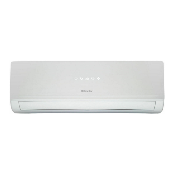
- Page 1 Model: DCSS09 (2.5kW Cooling / 2.6kW Heating) DCSS18 (5.0kW Cooling / 5.2kW Heating)
-
Page 2: Table Of Contents
CONTENTS ....................1 SAFETY PRECAUTIONS .........................4 NAMES OF PARTS INDOOR UNIT DISPLAY ......................5 EMERGENCY FUNCTION & AUTO-RESTART FUNCTION ..........6 REMOTE CONTROLLER ......................7 OPERATING INSTRUCTIONS .....................10 .........................15 PROTECTION INSTALLATION MANUAL ....................16 MAINTENANCE ........................25 ......................26 TROUBLESHOOTING... - Page 3 SAFETY RULES AND RECOMMENDATIONS FOR THE INSTALLER Do not install the appliance at a distance of Read this guide before installing and using the less than 50 cm from inflammable substances appliance. (alcohol, etc.) Or from pressurised containers (e.g. spray cans). During the installation of the indoor and outd- oor units the access to the working area should If the appliance is used in areas without the...
- Page 4 SAFETY RULES AND RECOMMENDATIONS FOR THE USER Do not try to install the conditioner alone; Never remain directly exposed to the flow of always contact specialized technical personnel. cold air for a long time. The direct and prolo- nged exposition to cold air could be dangero- Cleaning and maintenance must be carried out us for your health .Particular care should be by specialised technical personnel.
- Page 5 SAFETY RULES AND PROHIBITIONS Do not bend , tug or compress the power cord Do not climb onto or place any heavy or hot since this could damage it. Electrical shocks or objects on top of the appliance. fire are probably due to a damaged power cord. Do not leave windows or doors open for long Specialised technical personnel only must repl- when the air conditioner is operating.
-
Page 6: Names Of Parts
NAMES OF PARTS INDOOR UNIT INDOOR UNIT Description Front panel Air filter Optional filter (if installed) LED Display Signal receiver Terminal block cover Ionizer generator (if installed) Deflectors Emergency button Indoor unit rating label ( Stick position optional Airflow direction louver Remote controller OUTDOOR UNIT No. -
Page 7: Indoor Unit Display
INDOOR UNIT DISPLAY Function This symbol appears when the unit is power on POWER SLEEP mode SLEEP (1) Lights up during Timer operation when the air conditioner is operational Temperature display (if present) (2)Displays the malfunction code when fault /Error code occurs. -
Page 8: Emergency Function & Auto-Restart Function
EMERGENCY FUNCTION & AUTO-RESTART FUNCTION AUTO-RESTART FUNCTION The appliance is preset auto - restart function by manufacturer. In case of a sudden power failure, the ON / OFF module memorizes the setting conditions before the power failure. when the power restores, the unit restarts automatically with all the previous settings preserved by the memory function. -
Page 9: Remote Controller
REMOTE CONTROLLER Button Function (TEMP UP) Press it to increase temperature / time setting. (TEMP DN) Press it to decrease temperature/ time setting. CLOCK DISPLAY HEALTHY ON/OFF Press it to start or stop operation. ON/OFF SWING To select the fan speed of auto/low/mid/high TIMER SUPER SLEEP... - Page 10 REMOTE CONTROLLER Remote controller DISPLAY Meaning of symbols on the liquid crystal display Symbols Meaning HEALTHY TIMER FEEL mode indicator COOLING indicator DEHUMIDIFYING indicator FEEL SPEED AUTOQUIET COOL FAN ONLY OPERATION indicator POWERFUL SWING DELAY HEAT HEATING indicator HEALTHY TIMER SIGNAL RECEPTION indicator TIMER OFF indicator TIMER...
-
Page 11: Replacement Of Batteries
REMOTE CONTROLLER Replacement of Batteries Remove the battery cover plate from the rear of the remote controller, by sliding it in the direction of the arrow. nstall the batteries according the direction (+and -)shown on the Remote Controller. Reinstall the battery cover by sliding it into place. Use 2 LRO 3 AAA (1.5V) batteries . -
Page 12: Operating Instructions
OPERATING INSTRUCTIONS The air sucked by the fan enters from the grill and passes through the filter, then it is cooled/dehumidified Filter or heated through the heat exchanger. Heat Exchanger The direction of the air outlet is motorized up and down by flaps, and manually moved right and left by the vertical deflectors, for some models, the vertical deflectors could be controlled by motor as well. -
Page 13: Cooling Mode Cool
OPERATING INSTRUCTIONS COOLING MODE COOL The cooling function allows the air condit- FEEL COOL SPEED AUTOQUIET COOL ioner to cool the room and at the same time POWERFUL reduces Air humidity. SWING DELAY HEAT To activate the cooling function ( COOL ) , press the HEALTHY TIMER MODE button until the symbol... - Page 14 OPERATING INSTRUCTIONS TIMER MODE----TIMER ON TIMER To set the time of the air conditioner FEEL SPEED AUTOQUIET COOL TIMER POWERFUL SWING DELAY To program the automatical switching-on time, the HEAT HEALTHY TIMER appliance should be power off. Press TIMER at the fist time , set the temperature with pressing the button Press TIMER at the second time , set the rest time with ON/OFF...
-
Page 15: Fan Mode
OPERATING INSTRUCTIONS FAN MODE The conditioner works in only FEEL SPEED AUTOQUIET COOL ventilation. POWERFUL SWING DELAY HEAT To set the FAN mode , Press MODE untill HEALTHY TIMER ( FAN ) appears in the display. Whith pressing button the speed changes ON/OFF in the following sequence: LOW/ MEDIUM/HIGH /AUTO in FAN mode. -
Page 16: Sleep Mode
OPERATING INSTRUCTIONS I FEEL MODE FEEL Automatic mode. I FEEL FEEL SPEED AUTOQUIET COOL POWERFUL SWING DELAY To activate the I FEEL (automatic) mode of operation, HEAT HEALTHY TIMER press the MODE button on the remote controller until the symbol ( I FELL ) appears on the display. -
Page 17: Protection
PROTECTION The air conditioner is programmed for comfortable and suitable living conditions, if it is used in abnormal conditioner as below, certain safety protection features might come into effect. For T1 Climate condition models: Ambient temperature MODE Outdoor temperature is over 24 Outdoor temperature is below -7 Heating Room temperature is over 27... -
Page 18: Installation Manual
INSTALLATION MANUAL---Selecting the Installation Place INDOOR UNIT Install the indoor unit on a strong wall that is not subject Mounting plate to vibrations. The in let and outlet ports should not be obstructed:the air should be able to blow all over the room. Do not install the unit near a source of heat , steam,or flammable gas. - Page 19 INSTALLATION MANUAL---Installation of the Indoor unit Before starting installation, decide on the position of the indoor and outdoor units, taking into account the minim- um space reserved around the units Do not install your air conditioner in a wet room such as a bathroom or laundry etc The installation site should be 250cm or more above the floor.
-
Page 20: Refrigerant Piping Connection
INSTALLATION MANUAL---Installation of the Indoor unit Refrigerant piping connection The piping can be run in the 3 directions indicated by numbers in the picture . When the piping is run in direction 1or3, cut a notch along the groove on the side of the indoor unit with a cutter. -
Page 21: Installation Of The Indoor Unit
INSTALLATION MANUAL---Installation of the Indoor unit INSTALLATION OF THE INDOOR UNIT After having connected the pipe according to the instruc- Covered by vinyl tape tions, install the connection cables. Now install the drain refrigerant insulation pipe. After connection,lag the pipe, cables and drain pipe pipe sleeve connection... -
Page 22: Electrical Connections
INSTALLATION MANUAL---Installation of the outdoor unit ELECTRICAL CONNECTIONS wiring diagram on the back of the cover 1. Remove the handle on the right side plate of outdoor unit. 2. Connect the power connection cord to the terminal board. Wiring should fit that of indoor unit. 3. - Page 23 INSTALLATION MANUAL---Installation of the outdoor unit BLEEDING 3-way valve diagram The air and humidity left inside the refrigerant circulat- ion can cause compressor malfunction. After having co- connect to indoor unit nnected the indoor and outdoor units, bleed the air and humidity from the refrigerant circulation using a va- open position cuum pump.
- Page 24 INSTALLATION MANUAL---Information for the installer FIXED-SPEED TYPE 22/24k 28/30k/36k 15/18k MODEL capacity (Btu/h) Liquid pipe diameter ( 6) ( 6) ( 6) ( 6) ( 6) ( 9.52) ( 9.52) Gas pipe diameter ( 9.52) ( 9.52) ( 9.52) ( 12) ( 12) ( 15.88) ( 15.88)
- Page 25 INSTALLATION MANUAL---Information for the installer WIRING DIAGRAM For different models, the wiring diagram may be different. Please refer to the wiring diagrams pasted on the indoor unit and outdoor unit respectively. On indoor unit, the wiring diagram is pasted under the front panel; On outdoor unit, the wiring diagram is pasted on the backside of the outdoor handle cover.
- Page 26 INSTALLATION MANUAL---Information for the installer CABLE WIRES SPECIFICATION 22/24k 28/30k/36k 15/18k MODEL capacity (Btu/h) sectional area 1.0mm 2.5mm 1.0mm 1.0mm 1.0mm 1.5mm 4.0mm (1.5mm) AWG14 AWG12 AWG18 AWG18 AWG18 AWG18 AWG16 H05RN-F (AWG16) Power supply cable 1.0mm 2.5mm 1.0mm 1.0mm 1.0mm 1.5mm 4.0mm...
-
Page 27: Maintenance
MAINTENANCE Periodic maintenance is essential for keeping your air conditioner efficient. Before carrying out any maintenance , disconnect the power supply by taking the plug out from the socket. INDOOR UNIT ANTIDUST FILTERS 1. Open the front panel following the direction of the arrow 2. -
Page 28: Troubleshooting
TROUBLESHOOTING MALFUNCTION POSSIBLE CAUSES Power failure/plug pulled out Damaged indoor/outdoor unit fan motor Faulty compressor thermomagnetic circuit breaker The appliance does not Faulty protective device or fuses. operate Loose connections or plug pulled out It sometimes stops operating to protect the appliance. Voltage higher or lower than the voltage range Active TIMER-ON function Damaged electronic control board... - Page 29 CONTACT DETAILS Glen Dimplex Australia Pty Ltd 1/21 Lionel Road Mount Waverley VIC 3149 Australia Ph: 1300 556 816 Web: www.dimplex.com.au Glen Dimplex New Zealand Ltd 38 Harris Road East Tamaki, Auckland New Zealand Ph: 09 274 8265 Web: www.dimplex.co.nz...