Table of Contents
Advertisement
Quick Links
IMPORTANT SAFETY INFORMATION: Always read this manual first before attempting to service this fireplace. For your
safety, always comply with all warnings and safety instructions contained in this manual to prevent personal injury or prop-
erty damage.
Dimplex North America Limited
1367 Industrial Road Cambridge ON Canada N3H 4W3
1-888-346-7539 www.dimplex.com
In keeping with our policy of continuous product development, we reserve the right to make changes without notice.
© 2016 Dimplex North America Limited
Service Manual
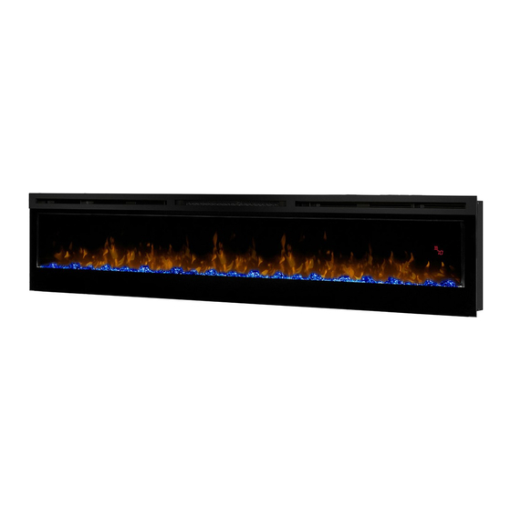
Model
BLF7451
UL Part Number
6909610100
REV
PCN
DATE
00
-
5-JAN-16
7400900000R00
Advertisement
Table of Contents

Related Manuals for Dimplex BLF7451


Summary of Contents for Dimplex BLF7451
- Page 1 Dimplex North America Limited 5-JAN-16 1367 Industrial Road Cambridge ON Canada N3H 4W3 1-888-346-7539 www.dimplex.com In keeping with our policy of continuous product development, we reserve the right to make changes without notice. © 2016 Dimplex North America Limited 7400900000R00...
-
Page 2: Table Of Contents
NOTE: Procedures and techniques that are considered important enough to emphasize. CAUTION: Procedures and techniques which, if not carefully followed, will result in damage to the equipment. WARNING: Procedures and techniques which, if not carefully followed, will expose the user to the risk of fire, serious injury, or death. www.dimplex.com... -
Page 3: Operation
OPERATION by initial heating of internal heater parts and will not occur again. Figure 1 D & E . Thermostat Controls Adjusts the temperature set point to your individual require- ments. Once the desired set temperature is reached the heater will turn off. The heater will cycle on and off to main- tain the desired set temperature. -
Page 4: Maintenance
2. Correctly install one 3 Volt (CR2032 [longer life] or other servicing. CR2025) battery in the battery holder. 3. Close the battery cover. Battery must be recycled or disposed of properly. Check with your Local Authority or Retailer for recyc- ling advice in your area www.dimplex.com... -
Page 5: Exploded Parts Diagram
EXPLODED PARTS DIAGRAM REPLACEMENT PARTS LIST 1. Element......2200510700RP 12. Media LED Light Strip (RGB) (6 per unit) 3001570300RP 2. -
Page 6: Wiring Diagram
WIRING DIAGRAM RELAY BOARD SWITCH BOARD LED STRIPS LED STRIPS (RGB) - MEDIA (RGB) - FLAME BLOWER MOTOR ELEMENTS FLICKER MOTOR CUTOUT THERMAL THERMISTOR AC/DC ADAPTER DISPLAY / CONTROL BOARD FLAME LED STRIPS (AMBER) LED DRIVER BOARDS www.dimplex.com... -
Page 7: Preparation For Service
PREPARATION FOR SERVICE Figure 3 NOTE: All components are replaceable from the front of the fireplace while the unit is mounted on the wall, with the exception of replacement of the power cord. NOTE: If the power cord needs replacing or if the unit needs to be removed from the wall for any other reason please begin service by following the “PREPARATION FOR SERVICE”... -
Page 8: Flush Mount - Complete In-Wall
1. Remove the 2 screws, that secure the controls assem- 2. Locate and remove the 4 mounting screws inside the Figure 7 unit located on left and right side towards the front. Figure 6 Wall Surface Mounting Hole www.dimplex.com... -
Page 9: Relay Board Replacement
Figure 8 Figure 9 Controls Assembly 6 LED AC/DC Driver Board Power 12 LED Adapter Driver Board Relay Board Switch Board Retaining Screws ceiver to the new relay board. bly (Figure 8), located at the top of the mirror on the NOTE: Using a flat head screwdriver gently pry be- right side of the unit. -
Page 10: Ad/Dc Adapter Replacement
7. Remove the four screws that secure the AC/DC adapter bracket to the controls assembly. Rubber Flicker Front 8. Install the new AC/DC adapter and install all wiring con- Gasket Motor Panel nections. www.dimplex.com... -
Page 11: Flicker Motor Replacement
FLICKER ROD REPLACEMENT Figure 11 WARNING: Disconnect power before attempting any maintenance or cleaning to reduce the risk of electric shock or damage to persons. Media CAUTION: If unit was operating prior to servicing allow Tray at least 10 minutes for lights and heating elements to cool off to avoid accidental burning of skin. -
Page 12: High Temperature Cutout Replacement
CAUTION: If unit was operating prior to servicing allow at least 10 minutes for lights and heating elements to cool off to avoid accidental burning of skin. Tools required: Phillips head screwdriver Blower Heating Needle nosed pliers Assembly Cover www.dimplex.com... -
Page 13: Blower/Fan Replacement
2. Remove the Partially Reflective Glass by removing the CAUTION: If unit was operating prior to servicing allow 2 screws on each retaining bracket, located on the left at least 10 minutes for lights and heating elements to cool and right side of the Partially Reflective Glass. (Figure off to avoid accidental burning of skin. -
Page 14: Thermistor Replacement
6. Loosely wrap the provided tie wrap through the hole in Figure 15 Thermistor Figure 16 Flame panel Left Cover Top Panel of Unit trough Panel Display / Control Partially Board Reflective Glass Standoff 1.5 in. (3.8 cm) Tie Wrap Retaining Thermistor Brackets www.dimplex.com... -
Page 15: Troubleshooting Guide
TROUBLESHOOTING GUIDE PROBLEM CAUSE SOLUTION PART NUMBER General Circuit breaker trips or fuse Short in unit wiring. Trace wiring in unit. blows when unit is turned on Improper circuit current rating Additional appliances may exceed the current rating of the circuit breaker or fuse. Plug unit into another outlet or install unit on a dedicated 15 amp circuit. - Page 16 Grinding or excessive noise Flicker rod hitting or rubbing Ensure rod is straight and mounted properly with the heater off against internal components in the bracket, spinning freely away from other components. Replace if necessary. Defective Flicker Motor Replace Flicker Motor 2000220100RP www.dimplex.com...