Advertisement
Quick Links
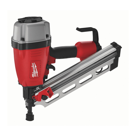
CATALOG NO. 7110-20
1
20
2
3
21
4
22
5
8
6
23
7
9
10
24
11
25
13
12
26
14
27
15
16
28
17
18
29
19
FIG.
PART NO.
DESCRIPTION OF PART
1
05-84-0945
Defl ector Bolt
2
45-88-1725
Defl ector Screw Pad
3
31-05-0410
Defl ector
4
45-88-1715
Defl ector Pad
5
43-31-0350
Muffl er Assembly
6
05-84-0865
Bolt Assembly w/Washer
7
42-92-1430
Top Cap
8
05-84-0955
Set Screw, M5 x 0.8-5
9
45-06-0900
Top Cap Seal
10
40-50-3115
Upper Valve Spring
11
34-40-3255
O-Ring, 43.5 mm x 2.62 mm
12
34-40-3230
O-Ring, 60.2 mm x 3.1 mm
13
34-40-3260
O-Ring, 47.8 mm x 2.62 mm
14
44-62-0255
Head Valve Piston
15
42-76-0805
Valve Collar
16
31-94-0100
Valve
17
45-06-0930
Seal
18
05-83-0520
Hex Bolt, M6 x 1.0-12
19
44-90-0745
Steel Ring
20
44-90-0735
Press Ring
21
44-90-0810
Piston Ring
22
34-40-3135
O-Ring
23
43-12-0275
Driver Assembly
24
42-98-0360
Cylinder
25
34-40-3140
O-Ring
26
44-90-0795
Cylinder Spacer
SERVICE PARTS LIST
SPECIFY CATALOG NO. AND SERIAL NO. WHEN ORDERING PARTS
CLIPPED HEAD FRAMING NAILER
STARTING
SERIAL NUMBER
30
50
47
63
64
65
66
67
68
69
70
71
72
NO. REQ.
1
1
1
1
1
4
1
1
1
1
1
1
1
1
1
1
1
4
1
1
1
1
1
1
1
1
A86A
60
55
54
53
52
51
99
86
31
32
33
43
42
46
45
44
FIG.
PART NO.
DESCRIPTION OF PART
27
34-40-3150
O-Ring
28
44-90-0720
Cylinder Ring
29
42-38-0310
Bumper
30
42-38-0375
Bumper Band
31
34-40-3295
O-Ring
32
34-40-3300
O-Ring
33
42-52-0410
Plunger Cap
34
34-40-3280
O-Ring
35
34-40-3285
O-Ring
36
44-70-0250
Valve Plunger
37
40-50-3195
Spring
38
34-40-3290
O-Ring
39
44-70-0255
Trigger Valve Plunger
40
43-64-0150
Trigger Valve Head
41
06-65-1465
Spring Pin
42
06-65-1440
Spring Pin
43
06-65-1435
Spring Pin
44
43-56-0875
Work Contact Element Guide
45
44-10-0655
Selector
46
40-50-3095
Selector Spring
47
44-86-0710
Retainer
48
40-50-3160
Trigger Spring
49
31-92-0200
Trigger Assembly
50
44-90-0825
Ring
51
28-50-0810
Tool Body
52
44-90-0755
Retaining Ring
53
43-31-0375
Inlet Filter
54
42-92-1360
End Cap
55
34-40-3225
O-Ring
56
05-84-0950
Socket Hex Head Screw
57
40-50-3180
Spring
58
45-08-0460
Positioning Shaft
59
42-70-0405
Spring Retainer (Rafter Hook)
60
05-83-0535
Round Head Philips Bolt
63
40-50-3070
Work Contact Spring
64
44-90-0775
E-Ring
65
42-36-2020
Work Contact Bracket B
66
44-94-0550
Adjust Rod Assembly
67
43-98-0750
Adjustment Knob
68
40-50-3175
Adjustment Spring
69
42-36-2000
Work Contact Bracket A
70
44-90-0705
Ring
71
42-38-0330
No-mar Pad
72
44-90-0715
Fixed Ring
13135 W. Lisbon Road, Brookfi eld, WI 53005
PAGE 1 OF 2
BULLETIN NO.
54-43-0020
REVISED BULLETIN
DATE
Feb. 2007
WIRING INSTRUCTION
56
57
58
59
41
36
35
31 32 33 34 35 36
102
34
37 38 39 40 41 50
37
38
39
EXAMPLE:
00
Component Parts
0
40
(Small #) Are Included
48
When Ordering The
Assembly (Large #).
49
MILWAUKEE ELECTRIC TOOL CORPORATION
NO. REQ.
1
1
1
1
1
1
1
1
2
1
1
2
1
1
2
3
1
1
1
1
1
1
1
1
1
1
1
1
1
1
1
1
1
1
1
1
1
1
1
1
1
1
1
1
Drwg.3
Advertisement

Related Manuals for Milwaukee 7110-20


Summary of Contents for Milwaukee 7110-20
- Page 1 SPECIFY CATALOG NO. AND SERIAL NO. WHEN ORDERING PARTS CATALOG NO. 7110-20 FIG. PART NO. DESCRIPTION OF PART 05-84-0945 Defl ector Bolt 45-88-1725 Defl ector Screw Pad 31-05-0410 Defl ector 45-88-1715 Defl ector Pad 43-31-0350 Muffl er Assembly 05-84-0865 Bolt Assembly w/Washer...
- Page 2 FIG. PART NO. DESCRIPTION OF PART 34-40-3145 O-Ring 30-61-0210 Nose Piece 05-84-0870 Bolt Assembly 43-40-0480 Magazine A 43-72-0365 Pusher 40-50-3135 Pusher Button Spring 42-28-0370 Square Stop Bracket 05-84-0885 Socket Hex Head Screw 40-50-3145 Spring 44-96-0200 Spring Roller 06-65-1400 42-92-1525 Protecting Hood Cover 44-86-0705 Retainer Ring 44-60-1920...
- Page 3 Disassembly: 7, 10, 11, 12, 13, 14, 15, Remove valve assembly (10-17) from top cap (7) by removing hex bolt (18) in a counter clockwise direction. 16, 17, 18 Note: Assembly is spring loaded. Hold assembly in place while removing hex bolt (18). 23, 24, 51, 19, 20 Remove driver assembly (23) and cylinder assembly (24) from tool body (51) by turning the tool body (51) upside down and tapping the outside rim of the tool casting against a piece of wood.
- Page 4 Lubrication: Type I Grease 49-08-7100 Clean all parts with a dry clean cloth. 7, 10, 11, 12, 13, 14, 15, Place a thin coating of grease into internal bore of top cap (7), coat parts (10-17) and reassemble in order shown. 16, 17 21, 22, 23 Coat o-ring (22) and piston ring (21) prior to installing into groove of driver assembly (23).